EP1069269A1 - Verriegelungseinrichtung - Google Patents
Verriegelungseinrichtung Download PDFInfo
- Publication number
- EP1069269A1 EP1069269A1 EP00306055A EP00306055A EP1069269A1 EP 1069269 A1 EP1069269 A1 EP 1069269A1 EP 00306055 A EP00306055 A EP 00306055A EP 00306055 A EP00306055 A EP 00306055A EP 1069269 A1 EP1069269 A1 EP 1069269A1
- Authority
- EP
- European Patent Office
- Prior art keywords
- striker
- latch mechanism
- pawl
- latch
- limiting member
- Prior art date
- Legal status (The legal status is an assumption and is not a legal conclusion. Google has not performed a legal analysis and makes no representation as to the accuracy of the status listed.)
- Granted
Links
Images
Classifications
-
- E—FIXED CONSTRUCTIONS
- E05—LOCKS; KEYS; WINDOW OR DOOR FITTINGS; SAFES
- E05B—LOCKS; ACCESSORIES THEREFOR; HANDCUFFS
- E05B77/00—Vehicle locks characterised by special functions or purposes
- E05B77/02—Vehicle locks characterised by special functions or purposes for accident situations
- E05B77/10—Allowing opening in case of deformed bodywork, e.g. by preventing deformation of lock parts
Definitions
- the present invention relates to latch assemblies and in particular to latch assemblies for releasably securing vehicle doors when such doors are in a closed position.
- a typical vehicle door latch mechanism essentially comprises a rotatable claw mounted on the vehicle door which co-operates with a striker pin mounted on the vehicle body.
- the action of closing the door causes the claw to rotate to a closed position whereupon it engages and retains the striker pin.
- the claw is maintained in the closed position by a sprung pawl which abuts an appropriately shaped portion of the claw.
- forces experienced by the latch mechanism can lead to relative movement between the claw and pawl, with the result that the two become misaligned and the pawl no longer maintains the claw in the closed position.
- the present invention seeks to provide a latch mechanism which is less likely to unlatch during an accident.
- a latch mechanism having a latch bolt for releasably securing a striker in a closed position, the latch bolt being movably mounted on a chassis of the latch mechanism, and a pawl movably mounted on the chassis and engageable with the latch bolt to releasably secure it in a closed position, the latch mechanism further including a limiting member mounted in the chassis, the limiting member being positioned adjacent the pawl and latch bolt so as to limit relative movement therebetween by co-operation with an engagement portion of the striker when the striker is secured in the closed position following the application of an abnormal load to the latch mechanism.
- the limiting member is configured so as to substantially surround a portion of the striker when the striker is secured in the closed position.
- the limiting member may be substantially planar and provided with a mouth adapted to receive said portion of the striker.
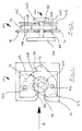
- the mechanism 10 includes a pawl 12, a latch bolt in the form of a claw 14, and a retention plate 16.
- the pawl 12 is pivotally mounted via a pawl pivot 20 which is connected to the retention plate 16.
- the pawl pivot 20 is defined by a pin extending from the retention plate 16.
- the pawl 12 includes a pawl engagement portion 22.
- the retention plate 16 in conjunction with further components of the latch mechanism 10 (not shown) which do not move relative to the retention plate 16 during use, form a chassis of the latch mechanism.
- the claw 14 is pivotally mounted on a claw pivot 24 which is secured to the retention plate 16. in the embodiment shown the claw pivot 24 is defined by a pin extending from the retention plate 16
- the claw 14 includes a claw jaw 26 and a claw closed engagement portion 28 and a claw first safety engagement portion 30.
- the retention plate 16 includes a mouth 32.
- the claw jaw 26 releasably secures a striker 34 in the mouth 32 of the retention plate 16.
- the claw 14 can be secured in its closed position, as shown in figure 1, by the pawl 12, and in particular by abutment of the pawl engagement portion 22 with the claw closed engagement portion 28.
- the striker 34 comprises a pin 36 having at opposite ends thereof a base 38 and an end flange 40. In use, the base 38 of the striker 34 is secured at a location of a vehicle body.
- Known release means allow the pawl 12 to be rotated anticlockwise when viewing figure 1 to disengage the pawl engagement portion 22 from the claw closed engagement portion 28, to allow the claw 14 to rotate in an anticlockwise direction and thus release the striker 34 form the mouth 32.
- the pawl 12 and claw 14 are substantially planar having respective first planar sides 12A and 14A, and second planar sides 12B and 14B.
- the retention plate 16 is positioned on the respective first sides 12A, 14A of the pawl 12 and claw 14.
- the pawl 12 and claw 14 are pivotable about respective pivot axes 12C and 14C which, in the embodiment shown, are substantially parallel.
- the retention plate 16 Under abnormal conditions, such as when the latch mechanism is secured in a door of a vehicle and the door receives a side impact during a road traffic accident, the retention plate 16 can be distorted with the result that the alignment pivot axes 12C and 14C changes. This can lead to the pawl engagement portion becoming misaligned with the claw closed engagement portion 28, and thereby allowing the door to open.
- the latch mechanism 10 is provided with a substantially planar striker engagement plate 42 within the chassis of the latch mechanism.
- the striker engagement plate 42 is positioned in the chassis such that it lies on the respective second sides 12B,14B of the pawl 12 and claw 14.
- striker engagement plate 42 is arranged substantially parallel to the retention plate 16 and may be carried by the pins defining the pawl and claw pivots 20,24.
- the claw jaw 26 releasably secures the striker 34 both in the mouth 32 of the retention plate 16 and a corresponding mouth 44 of the striker engagement plate 42.
- the striker engagement plate 42 is positioned between the claw 12 and pawl 14 and the end flange of the 40 of the striker 34. Under the abnormal conditions described above, the striker engagement plate 42 acts to resist misalignment of the pawl 12 and claw 14.
- Movement of the claw 12 and/or pawl 14 can result in each or either of them moving into contact with the retention plate 16 and/or the striker engagement plate 42, with the plates 16,42 then acting to constrain further movement of the claw 12 and/or pawl 14.
- the proximity of the striker engagement plate 42 to the striker end flange 40 means that any distortion or flexing of the striker engagement plate 42 causes it to abut the end flange 40. Further distortion or flexing of the striker engagement plate 42 is resisted by the end flange 40.
Landscapes
- Lock And Its Accessories (AREA)
Applications Claiming Priority (2)
| Application Number | Priority Date | Filing Date | Title |
|---|---|---|---|
| GB9916632 | 1999-07-16 | ||
| GBGB9916632.4A GB9916632D0 (en) | 1999-07-16 | 1999-07-16 | Latch mechanism |
Publications (2)
| Publication Number | Publication Date |
|---|---|
| EP1069269A1 true EP1069269A1 (de) | 2001-01-17 |
| EP1069269B1 EP1069269B1 (de) | 2005-03-02 |
Family
ID=10857306
Family Applications (1)
| Application Number | Title | Priority Date | Filing Date |
|---|---|---|---|
| EP20000306055 Expired - Lifetime EP1069269B1 (de) | 1999-07-16 | 2000-07-17 | Verriegelungseinrichtung |
Country Status (3)
| Country | Link |
|---|---|
| EP (1) | EP1069269B1 (de) |
| DE (1) | DE60018332T2 (de) |
| GB (1) | GB9916632D0 (de) |
Cited By (2)
| Publication number | Priority date | Publication date | Assignee | Title |
|---|---|---|---|---|
| DE102006031226A1 (de) * | 2006-07-06 | 2008-01-17 | Audi Ag | Schloss für eine Fahrzeugtür |
| CN102345420A (zh) * | 2010-08-03 | 2012-02-08 | 通用汽车环球科技运作有限责任公司 | 闩锁系统 |
Citations (4)
| Publication number | Priority date | Publication date | Assignee | Title |
|---|---|---|---|---|
| GB1561538A (en) * | 1976-11-29 | 1980-02-20 | Chrysler Uk | Vehicle bodies |
| GB2285481A (en) * | 1994-01-11 | 1995-07-12 | Mitsui Mining & Smelting Co | Apparatus mounting a latch device to a sliding door |
| FR2760778A1 (fr) * | 1997-03-11 | 1998-09-18 | Valeo Systemes De Fermetures | Serrure pour vehicule automobile |
| US5860683A (en) * | 1995-06-09 | 1999-01-19 | Ohi Seisakusho Co., Ltd. | Automotive door lock device |
-
1999
- 1999-07-16 GB GBGB9916632.4A patent/GB9916632D0/en not_active Ceased
-
2000
- 2000-07-17 DE DE2000618332 patent/DE60018332T2/de not_active Expired - Fee Related
- 2000-07-17 EP EP20000306055 patent/EP1069269B1/de not_active Expired - Lifetime
Patent Citations (4)
| Publication number | Priority date | Publication date | Assignee | Title |
|---|---|---|---|---|
| GB1561538A (en) * | 1976-11-29 | 1980-02-20 | Chrysler Uk | Vehicle bodies |
| GB2285481A (en) * | 1994-01-11 | 1995-07-12 | Mitsui Mining & Smelting Co | Apparatus mounting a latch device to a sliding door |
| US5860683A (en) * | 1995-06-09 | 1999-01-19 | Ohi Seisakusho Co., Ltd. | Automotive door lock device |
| FR2760778A1 (fr) * | 1997-03-11 | 1998-09-18 | Valeo Systemes De Fermetures | Serrure pour vehicule automobile |
Cited By (4)
| Publication number | Priority date | Publication date | Assignee | Title |
|---|---|---|---|---|
| DE102006031226A1 (de) * | 2006-07-06 | 2008-01-17 | Audi Ag | Schloss für eine Fahrzeugtür |
| DE102006031226B4 (de) * | 2006-07-06 | 2012-05-31 | Audi Ag | Schloss für eine Fahrzeugtür |
| CN102345420A (zh) * | 2010-08-03 | 2012-02-08 | 通用汽车环球科技运作有限责任公司 | 闩锁系统 |
| CN102345420B (zh) * | 2010-08-03 | 2014-06-25 | 通用汽车环球科技运作有限责任公司 | 闩锁系统 |
Also Published As
| Publication number | Publication date |
|---|---|
| DE60018332T2 (de) | 2005-06-30 |
| GB9916632D0 (en) | 1999-09-15 |
| DE60018332D1 (de) | 2005-04-07 |
| EP1069269B1 (de) | 2005-03-02 |
Similar Documents
| Publication | Publication Date | Title |
|---|---|---|
| US10941592B2 (en) | Latch with double actuation and method of construction thereof | |
| CN102858567B (zh) | 车门锁闩 | |
| US9982468B2 (en) | Motor vehicle door lock | |
| EP1371799A2 (de) | Verriegelungsvorrichtung für eine Fahrzeugtür | |
| CN110984730B (zh) | 用于机动车辆闭合面板的闭合闩锁组件 | |
| US5685581A (en) | Actuating handle for motor-vehicle door latch | |
| US20180080266A1 (en) | Locking device for a vehicle door, and method | |
| JP2001521460A (ja) | 自動車用ドアとシャシの一体化 | |
| US20070069525A1 (en) | Vehicle door latching assembly including latch rod decoupling mechanism | |
| CN102791943A (zh) | 机动车门锁装置 | |
| US20110031767A1 (en) | Opening and/or closing mechanism on doors, gates/flaps or the like, in particular on motor vehicles | |
| EP1069269B1 (de) | Verriegelungseinrichtung | |
| US7128349B2 (en) | Motor-vehicle door latch | |
| EP1130201A2 (de) | Verriegelungsvorrichtung | |
| GB2361675A (en) | Latching arrangement of passenger door | |
| US8955890B2 (en) | Lockable vehicle closure bumpers | |
| EP1067261A1 (de) | Verriegelungsvorrichtung | |
| EP1069268A1 (de) | Verriegelungseinrichtung | |
| EP1070816B1 (de) | Verriegelungsvorrichtung | |
| CN116583653A (zh) | 机动车锁、特别是机动车门锁 | |
| US20020050720A1 (en) | Coupling device for door locking systems | |
| CN115298407B (zh) | 机动车锁 | |
| CN114072563B (zh) | 具有防叩击功能的带动力系紧机构的闭合闩锁组件 | |
| JPH10203169A (ja) | スライドドア支持装置 | |
| JPS5826285Y2 (ja) | 自動車用ドアロック装置におけるロック解除防止構造 |
Legal Events
| Date | Code | Title | Description |
|---|---|---|---|
| PUAI | Public reference made under article 153(3) epc to a published international application that has entered the european phase |
Free format text: ORIGINAL CODE: 0009012 |
|
| AK | Designated contracting states |
Kind code of ref document: A1 Designated state(s): DE FR GB |
|
| AX | Request for extension of the european patent |
Free format text: AL;LT;LV;MK;RO;SI |
|
| 17P | Request for examination filed |
Effective date: 20010504 |
|
| AKX | Designation fees paid |
Free format text: DE FR GB |
|
| RAP1 | Party data changed (applicant data changed or rights of an application transferred) |
Owner name: ARVINMERITOR LIGHT VEHICLE SYSTEMS (UK) LTD |
|
| 17Q | First examination report despatched |
Effective date: 20030523 |
|
| GRAP | Despatch of communication of intention to grant a patent |
Free format text: ORIGINAL CODE: EPIDOSNIGR1 |
|
| GRAS | Grant fee paid |
Free format text: ORIGINAL CODE: EPIDOSNIGR3 |
|
| GRAA | (expected) grant |
Free format text: ORIGINAL CODE: 0009210 |
|
| AK | Designated contracting states |
Kind code of ref document: B1 Designated state(s): DE FR GB |
|
| REG | Reference to a national code |
Ref country code: GB Ref legal event code: FG4D |
|
| REF | Corresponds to: |
Ref document number: 60018332 Country of ref document: DE Date of ref document: 20050407 Kind code of ref document: P |
|
| ET | Fr: translation filed | ||
| PLBE | No opposition filed within time limit |
Free format text: ORIGINAL CODE: 0009261 |
|
| STAA | Information on the status of an ep patent application or granted ep patent |
Free format text: STATUS: NO OPPOSITION FILED WITHIN TIME LIMIT |
|
| 26N | No opposition filed |
Effective date: 20051205 |
|
| PGFP | Annual fee paid to national office [announced via postgrant information from national office to epo] |
Ref country code: GB Payment date: 20060830 Year of fee payment: 7 |
|
| PGFP | Annual fee paid to national office [announced via postgrant information from national office to epo] |
Ref country code: FR Payment date: 20060908 Year of fee payment: 7 |
|
| PGFP | Annual fee paid to national office [announced via postgrant information from national office to epo] |
Ref country code: DE Payment date: 20060914 Year of fee payment: 7 |
|
| GBPC | Gb: european patent ceased through non-payment of renewal fee |
Effective date: 20070717 |
|
| PG25 | Lapsed in a contracting state [announced via postgrant information from national office to epo] |
Ref country code: DE Free format text: LAPSE BECAUSE OF NON-PAYMENT OF DUE FEES Effective date: 20080201 |
|
| PG25 | Lapsed in a contracting state [announced via postgrant information from national office to epo] |
Ref country code: GB Free format text: LAPSE BECAUSE OF NON-PAYMENT OF DUE FEES Effective date: 20070717 |
|
| REG | Reference to a national code |
Ref country code: FR Ref legal event code: ST Effective date: 20080331 |
|
| PG25 | Lapsed in a contracting state [announced via postgrant information from national office to epo] |
Ref country code: FR Free format text: LAPSE BECAUSE OF NON-PAYMENT OF DUE FEES Effective date: 20070731 |
|
| REG | Reference to a national code |
Ref country code: GB Ref legal event code: 732E |