EP1069247A1 - Construction machine - Google Patents
Construction machine Download PDFInfo
- Publication number
- EP1069247A1 EP1069247A1 EP00306000A EP00306000A EP1069247A1 EP 1069247 A1 EP1069247 A1 EP 1069247A1 EP 00306000 A EP00306000 A EP 00306000A EP 00306000 A EP00306000 A EP 00306000A EP 1069247 A1 EP1069247 A1 EP 1069247A1
- Authority
- EP
- European Patent Office
- Prior art keywords
- compartment
- construction machine
- muffler
- machine according
- engine
- Prior art date
- Legal status (The legal status is an assumption and is not a legal conclusion. Google has not performed a legal analysis and makes no representation as to the accuracy of the status listed.)
- Withdrawn
Links
Images

Classifications
-
- E—FIXED CONSTRUCTIONS
- E02—HYDRAULIC ENGINEERING; FOUNDATIONS; SOIL SHIFTING
- E02F—DREDGING; SOIL-SHIFTING
- E02F9/00—Component parts of dredgers or soil-shifting machines, not restricted to one of the kinds covered by groups E02F3/00 - E02F7/00
- E02F9/08—Superstructures; Supports for superstructures
- E02F9/0858—Arrangement of component parts installed on superstructures not otherwise provided for, e.g. electric components, fenders, air-conditioning units
- E02F9/0866—Engine compartment, e.g. heat exchangers, exhaust filters, cooling devices, silencers, mufflers, position of hydraulic pumps in the engine compartment
-
- E—FIXED CONSTRUCTIONS
- E02—HYDRAULIC ENGINEERING; FOUNDATIONS; SOIL SHIFTING
- E02F—DREDGING; SOIL-SHIFTING
- E02F9/00—Component parts of dredgers or soil-shifting machines, not restricted to one of the kinds covered by groups E02F3/00 - E02F7/00
-
- E—FIXED CONSTRUCTIONS
- E02—HYDRAULIC ENGINEERING; FOUNDATIONS; SOIL SHIFTING
- E02F—DREDGING; SOIL-SHIFTING
- E02F3/00—Dredgers; Soil-shifting machines
- E02F3/04—Dredgers; Soil-shifting machines mechanically-driven
- E02F3/28—Dredgers; Soil-shifting machines mechanically-driven with digging tools mounted on a dipper- or bucket-arm, i.e. there is either one arm or a pair of arms, e.g. dippers, buckets
- E02F3/30—Dredgers; Soil-shifting machines mechanically-driven with digging tools mounted on a dipper- or bucket-arm, i.e. there is either one arm or a pair of arms, e.g. dippers, buckets with a dipper-arm pivoted on a cantilever beam, i.e. boom
- E02F3/32—Dredgers; Soil-shifting machines mechanically-driven with digging tools mounted on a dipper- or bucket-arm, i.e. there is either one arm or a pair of arms, e.g. dippers, buckets with a dipper-arm pivoted on a cantilever beam, i.e. boom working downwardly and towards the machine, e.g. with backhoes
- E02F3/325—Backhoes of the miniature type
Definitions
- the present invention relates to a construction machine such as a hydraulic excavator.
- both an engine and an exhaust system are accommodated within an engine room.
- the exhaust system comprises, concretely, an exhaust pipe extending from an exhaust valve of the engine, a muffler connected to the exhaust pipe, and part of a tail pipe extending from the muffler. Heat generated from the engine and heat generated from the exhaust system are accumulated in the interior of the engine room of the conventional hydraulic excavator, so that the internal temperature of the engine room becomes high.
- the heat generated from the engine As to the heat generated from the engine, engine cooling water is cooled by a radiator; besides, cooling air is introduced from a cooling fan, thus permitting an increase of temperature to be suppressed.
- the heat generated from the exhaust system it causes an increase in the internal temperature of the engine room because any special cooling means is not provided.
- the heat generated from the muffler is a primary factor of the increase in temperature because of a large surface area of the muffler which is constituted by an expansion chamber. Once the internal temperature of the engine room thus rises, the ambient temperature of the radiator rises, resulting in that the cooling efficiency of the radiator deteriorates.
- a cylindrical cover is mounted around the muffler, or the surface of the muffler is coated with a heat insulating material such as glass wool.
- a heat insulating material such as glass wool
- the construction machine of the present invention has an upper rotating structure formed by a revolving frame, an engine room formed at a rear portion of the upper rotating structure and in which are accommodated at least an engine, a radiator, and a muffler, a compartment formed within the engine room and in which the muffler is accommodated, and a vent portion formed in the compartment to make communication between the outside air and the compartment through an underside of the upper rotating structure.
- the heat generated from the muffler is cut off in the compartment and is not transmitted into the engine room, and the outside air is introduced into the compartment through the vent portion, whereby an increase in temperature is suppressed.
- the outside air is introduced into the compartment through the vent portion, whereby an increase in temperature is suppressed.
- a bottom plate of the compartment may be a part of the revolving frame and the vent portion may be formed in the bottom plate. In this case, it becomes easier to form the compartment because the revolving frame constitutes the bottom plate of the compartment.
- the bottom plate may have an opening formed as a cutout portion and an undercover attached to the opening, and the vent portion may be formed in the undercover.
- the vent portion may be formed by directly cutting out a part of the revolving frame which constitutes the bottom plate. In the latter case, it is possible to attain the reduction of cost in forming the vent portion in the compartment because it is only forming apertures by cutting out the revolving frame that is required for the formation of the vent portion.
- the radiator may be mounted on a top plate of the compartment.
- the top plate of the compartment can be utilized as a mount for fixing the radiator, thus permitting a compact arrangement of the engine, radiator, and exhaust system.
- a fan which introduces the outside air forcibly into the compartment may be disposed near the vent portion.
- an increase in the internal temperature of the compartment can be suppressed more effectively because the interior of the compartment is ventilated forcibly by rotation of the fan.
- an exhaust pipe which connects the engine and the muffler with each other may be accommodated within the compartment, or at least a part of a tail pipe connected to the muffler may be accommodated within the compartment.
- a heat insulating member may be affixed to the compartment, or the compartment may be formed by the heat insulating member.
- the heat insulating member may be a rigid polyurethane foam panel. In these cases, it is possible to enhance the heat conduction cut-off effect.
- a vent hole communicating with the compartment may be formed in a side wall of the revolving frame and the outside air introduced into the compartment from the vent portion may be discharged through the vent hole.
- FIG. 1 illustrates an entire construction of a hydraulic excavator to which the present invention is applied.
- the hydraulic excavator is viewed from behind with an engine cover 1 open.
- the hydraulic excavator 2 comprises a lower travel body 3 and an upper rotating structure 4 mounted on the lower travel body rotatably.
- a front attachment 5 comprising a boom, an arm, and a bucket is attached to a front portion of the upper rotating structure 4.
- An operator seat 6 is disposed in the front portion of the upper rotating structure 4.
- a rear portion defined by a partition wall 4a of the upper rotating structure 4 serves as an engine room.
- an engine 7 Within the engine room are disposed an engine 7, a radiator 8 which constitutes a cooling system, a muffler 9 and a tail pipe 10 as constituents of an exhaust system, and a counter weight 11.
- Numeral 12 denotes a revolving frame.
- an exhaust pipe 13 extending obliquely downward from an exhaust valve 7a of the engine 7 is connected to an inlet 9a of the muffler 9 which is disposed below the engine 7.
- a tail pipe 11 extending substantially horizontally from an outlet 9b of the muffler 9 is conducted to the exterior through a through hole 12a formed in a rear end portion of a rear revolving frame 12.
- the muffler 9 is accommodated within a compartment 14.
- the compartment 14 is formed in the shape of a box by installing a gateway-like cover 14b on the revolving frame 12, the cover 14b having closed both side faces 14a.
- an opening 12b by cutting out the bottom plate, which opening 12b permits the muffler 9 to be inserted into the compartment 14 horizontally from the exterior.
- An undercover 15 is attached to the opening 12b.
- the undercover 15 In the undercover 15 are formed a large number of slit-like elongated apertures 15a in parallel with one another.
- the interior of the compartment 14 is in communication with the outside air through the elongated apertures 15a.
- a hot air which has been raised in temperature by the heat generated from the muffler 9 is exchanged with the outside air introduced into the compartment 14 and is then discharged.
- the elongated apertures 15a constitute a vent portion.
- slit-like apertures may be formed in a portion of the revolving frame 12 which portion is positioned at the bottom of the compartment 14, directly by cutting out the said frame portion, to constitute a vent portion.
- a top plate 14c of the compartment 14 also serves as a mount onto which the radiator 8 is to be installed.
- the radiator 8 and the engine 7 are connected together through an upper radiator hose 8a serving as a cooling water return pipe and a lower radiator hose 8b serving as a cooling water feed pipe.
- Cooling water which has been heat-exchanged and cooled by the radiator 8 is fed to the engine 7 from a lower portion of the radiator 8 by means of a water pump (not shown).
- cooling water which has been heat-exchanged with the engine 7 and thereby raised in temperature while circulating through the engine 7 is discharged from an upper portion of the engine 7 and is returned to the radiator 8 through the upper radiator hose 8a.
- the compartment 14 is constructed so as to cut off the heat generated from the muffler 9 and prevent it from being transmitted into the engine room.
- a device as the radiator 8 is installed on the compartment 14 formed in a box shape, thereby contributing to the reduction in size of the mounting space for the devices used in the cooling system and the exhaust system.
- the cooling efficiency of the compartment 14 can be enhanced by installing a fan in the vicinity of the vent portion to introduce the outside air forcibly into the compartment.
- a vent hole may be formed in a side wall of the revolving frame 12 and may be brought into communication with the interior of the compartment 14 through a duct or the like.
- the outside air is introduced into the compartment 14 from the vent portion formed in the bottom plate of the compartment and is heat-exchanged with the muffler 9, then the air thus heated to a high temperature is discharged from the vent hole formed in the side wall of the revolving frame.
- the muffler 9 which generates the largest amount of heat in the exhaust system is accommodated within the compartment 14 to cut off the conduction of heat.
- the other components of the exhaust system than the muffler are also accommodated within the compartment insofar as a sufficient space can be ensured in the engine room and ventilation can be effected.
- a heat insulating member may be affixed to the compartment 14 to enhance the heat conduction cut-off effect.
- the compartment 14 itself may be formed by a heat insulating member having rigidity such as a rigid polyurethane foam panel.
- the construction machine of the present invention is applicable not only to the above hydraulic excavator but also to a self-traveling crane such as a wheeled crane.
Landscapes
- Engineering & Computer Science (AREA)
- Mining & Mineral Resources (AREA)
- Civil Engineering (AREA)
- General Engineering & Computer Science (AREA)
- Structural Engineering (AREA)
- Mechanical Engineering (AREA)
- Component Parts Of Construction Machinery (AREA)
- Cooling, Air Intake And Gas Exhaust, And Fuel Tank Arrangements In Propulsion Units (AREA)
Abstract
A construction machine 2 is disclosed which comprises an upper rotating
structure 4 formed by a revolving frame 12, an engine room formed at a rear portion
of the upper rotating structure 4 and in which are accommodated at least an engine 7,
a radiator 8, and a muffler 9, a compartment 14 formed within the engine room and in
which the muffler 9 is accommodated, and a vent portion 15a formed in the
compartment 14 to make communication between the outside air and the
compartment 14 through an underside 15 of the upper rotating structure4. According
to this construction, heat generated from the muffler 9 is cut off in the compartment
14 and is not transmitted into the engine room, and the outside air is introduced into
the compartment 14 through the vent portion 15a to suppress an increase of
temperature. Consequently, it is possible to prevent deterioration in the cooling
efficiency of the radiator 8
Description
- The present invention relates to a construction machine such as a hydraulic excavator.
- In a conventional hydraulic excavator as a construction machine, both an engine and an exhaust system are accommodated within an engine room. The exhaust system comprises, concretely, an exhaust pipe extending from an exhaust valve of the engine, a muffler connected to the exhaust pipe, and part of a tail pipe extending from the muffler. Heat generated from the engine and heat generated from the exhaust system are accumulated in the interior of the engine room of the conventional hydraulic excavator, so that the internal temperature of the engine room becomes high.
- As to the heat generated from the engine, engine cooling water is cooled by a radiator; besides, cooling air is introduced from a cooling fan, thus permitting an increase of temperature to be suppressed. On the other hand, as to the heat generated from the exhaust system, it causes an increase in the internal temperature of the engine room because any special cooling means is not provided. Particularly, the heat generated from the muffler is a primary factor of the increase in temperature because of a large surface area of the muffler which is constituted by an expansion chamber. Once the internal temperature of the engine room thus rises, the ambient temperature of the radiator rises, resulting in that the cooling efficiency of the radiator deteriorates.
- According to the prior art, for solving such a problem, a cylindrical cover is mounted around the muffler, or the surface of the muffler is coated with a heat insulating material such as glass wool. However, when the conduction of heat reaches a steady state, heat is generated through the cover or the glass wool and thus the problem of increase in the internal temperature of the engine room has not thoroughly been solved yet.
- It is an object of the present invention to provide a construction machine capable of preventing an increase in the internal temperature of an engine room and consequent deterioration in the cooling efficiency of a radiator which are caused by the generation of heat from an exhaust system, especially a muffler.
- The construction machine of the present invention has an upper rotating structure formed by a revolving frame, an engine room formed at a rear portion of the upper rotating structure and in which are accommodated at least an engine, a radiator, and a muffler, a compartment formed within the engine room and in which the muffler is accommodated, and a vent portion formed in the compartment to make communication between the outside air and the compartment through an underside of the upper rotating structure.
- In the present invention, the heat generated from the muffler is cut off in the compartment and is not transmitted into the engine room, and the outside air is introduced into the compartment through the vent portion, whereby an increase in temperature is suppressed. Thus, it is possible to prevent deterioration in the cooling efficiency of the radiator.
- In the present invention, a bottom plate of the compartment may be a part of the revolving frame and the vent portion may be formed in the bottom plate. In this case, it becomes easier to form the compartment because the revolving frame constitutes the bottom plate of the compartment.
- The bottom plate may have an opening formed as a cutout portion and an undercover attached to the opening, and the vent portion may be formed in the undercover. Alternatively, the vent portion may be formed by directly cutting out a part of the revolving frame which constitutes the bottom plate. In the latter case, it is possible to attain the reduction of cost in forming the vent portion in the compartment because it is only forming apertures by cutting out the revolving frame that is required for the formation of the vent portion.
- In the present invention, the radiator may be mounted on a top plate of the compartment. In this case, the top plate of the compartment can be utilized as a mount for fixing the radiator, thus permitting a compact arrangement of the engine, radiator, and exhaust system.
- In the present invention, a fan which introduces the outside air forcibly into the compartment may be disposed near the vent portion. In this case, an increase in the internal temperature of the compartment can be suppressed more effectively because the interior of the compartment is ventilated forcibly by rotation of the fan.
- In the present invention, an exhaust pipe which connects the engine and the muffler with each other may be accommodated within the compartment, or at least a part of a tail pipe connected to the muffler may be accommodated within the compartment.
- Further, a heat insulating member may be affixed to the compartment, or the compartment may be formed by the heat insulating member. The heat insulating member may be a rigid polyurethane foam panel. In these cases, it is possible to enhance the heat conduction cut-off effect.
- Further, a vent hole communicating with the compartment may be formed in a side wall of the revolving frame and the outside air introduced into the compartment from the vent portion may be discharged through the vent hole.
-
- FIG. 1 is a perspective view showing an entire construction of a construction machine according to the present invention;
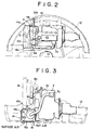
- FIG. 2 is a plan view showing how components are arranged within an engine room formed in the construction machine; and
- FIG. 3 is a front view of FIG. 2.
-
- The present invention will be described in detail hereinunder by way of an embodiment thereof illustrated in the drawings.
- FIG. 1 illustrates an entire construction of a hydraulic excavator to which the present invention is applied. In the same figure, the hydraulic excavator is viewed from behind with an engine cover 1 open.
- In FIG. 1, the
hydraulic excavator 2 comprises alower travel body 3 and an upperrotating structure 4 mounted on the lower travel body rotatably. Afront attachment 5 comprising a boom, an arm, and a bucket is attached to a front portion of the upper rotatingstructure 4. Anoperator seat 6 is disposed in the front portion of the upper rotatingstructure 4. A rear portion defined by a partition wall 4a of the upper rotatingstructure 4 serves as an engine room. Within the engine room are disposed anengine 7, aradiator 8 which constitutes a cooling system, amuffler 9 and atail pipe 10 as constituents of an exhaust system, and a counter weight 11. Numeral 12 denotes a revolving frame. - Now, with reference to the plan view of FIG. 2 and the front view of FIG. 3, the structure of the exhaust system, which is a characteristic portion of the present invention, will be described below.
- In both figures, an
exhaust pipe 13 extending obliquely downward from anexhaust valve 7a of theengine 7 is connected to aninlet 9a of themuffler 9 which is disposed below theengine 7. A tail pipe 11 extending substantially horizontally from anoutlet 9b of themuffler 9 is conducted to the exterior through athrough hole 12a formed in a rear end portion of a rear revolvingframe 12. - The
muffler 9 is accommodated within acompartment 14. Thecompartment 14 is formed in the shape of a box by installing a gateway-like cover 14b on the revolvingframe 12, thecover 14b having closed both side faces 14a. - In a bottom plate (the revolving frame 12) of the
compartment 14 there is formed an opening 12b by cutting out the bottom plate, which opening 12b permits themuffler 9 to be inserted into thecompartment 14 horizontally from the exterior. An undercover 15 is attached to the opening 12b. - In the undercover 15 are formed a large number of slit-like
elongated apertures 15a in parallel with one another. The interior of thecompartment 14 is in communication with the outside air through theelongated apertures 15a. According to this construction, a hot air which has been raised in temperature by the heat generated from themuffler 9 is exchanged with the outside air introduced into thecompartment 14 and is then discharged. Theelongated apertures 15a constitute a vent portion. - Instead of mounting the undercover 15, slit-like apertures may be formed in a portion of the revolving
frame 12 which portion is positioned at the bottom of thecompartment 14, directly by cutting out the said frame portion, to constitute a vent portion. - A
top plate 14c of thecompartment 14 also serves as a mount onto which theradiator 8 is to be installed. - The
radiator 8 and theengine 7 are connected together through an upper radiator hose 8a serving as a cooling water return pipe and alower radiator hose 8b serving as a cooling water feed pipe. - Cooling water which has been heat-exchanged and cooled by the
radiator 8 is fed to theengine 7 from a lower portion of theradiator 8 by means of a water pump (not shown). On the other hand, cooling water which has been heat-exchanged with theengine 7 and thereby raised in temperature while circulating through theengine 7 is discharged from an upper portion of theengine 7 and is returned to theradiator 8 through the upper radiator hose 8a. - Thus, the
compartment 14 is constructed so as to cut off the heat generated from themuffler 9 and prevent it from being transmitted into the engine room. Besides, such a device as theradiator 8 is installed on thecompartment 14 formed in a box shape, thereby contributing to the reduction in size of the mounting space for the devices used in the cooling system and the exhaust system. - The cooling efficiency of the
compartment 14 can be enhanced by installing a fan in the vicinity of the vent portion to introduce the outside air forcibly into the compartment. - A vent hole may be formed in a side wall of the revolving
frame 12 and may be brought into communication with the interior of thecompartment 14 through a duct or the like. In this case, the outside air is introduced into thecompartment 14 from the vent portion formed in the bottom plate of the compartment and is heat-exchanged with themuffler 9, then the air thus heated to a high temperature is discharged from the vent hole formed in the side wall of the revolving frame. - In this embodiment, moreover, the
muffler 9 which generates the largest amount of heat in the exhaust system is accommodated within thecompartment 14 to cut off the conduction of heat. However, it is preferable that the other components of the exhaust system than the muffler are also accommodated within the compartment insofar as a sufficient space can be ensured in the engine room and ventilation can be effected. - A heat insulating member may be affixed to the
compartment 14 to enhance the heat conduction cut-off effect. Thecompartment 14 itself may be formed by a heat insulating member having rigidity such as a rigid polyurethane foam panel. - The construction machine of the present invention is applicable not only to the above hydraulic excavator but also to a self-traveling crane such as a wheeled crane.
Claims (12)
- A construction machine (2) comprising:an upper rotating structure (4) formed by a revolving frame (12);an engine room formed at a rear portion of said upper rotating structure (4), with at least an engine (7), a radiator (8), and a muffler (9) being accommodated within said engine room;a compartment (14) formed within said engine room, with said muffler (9) being accommodated within said compartment (14); anda vent portion (15a) formed in said compartment (14), the venting portion (15a) providing communication between the outside air and said compartment (14) though an underside of said upper rotating structure.
- The construction machine (2) according to claim 1, wherein a bottom plate of the compartment (14) is constituted by a part of said revolving frame (12) and the vent portion (15a) is formed in said bottom plate.
- The construction machine according to claim 2, wherein said bottom plate has an opening (12b) formed as a cutout portion and an undercover (15) attached to the opening (12b), and said vent portion is formed in the undercover (15).
- The construction machine according to claim 2, wherein said vent portion (15b) is formed by directly cutting out a part of said revolving frame which constitutes said bottom plate.
- The construction machine according to any one of claims 1 to 4, wherein said radiator (8) is mounted on a top plate of the compartment.
- The construction machine according to any one of claims 1 to 5, further comprising:a fan disposed near said vent portion which introduces the outside air forcibly into the compartment.
- The construction machine according to any preceding claim wherein an exhaust pipe which connects said engine and said muffler with each other is further accommodated within said compartment.
- The construction machine according to any preceding claim, wherein at least a part of a tail pipe (10) connected to the muffler (9) is further accommodated within said compartment.
- The construction machine according to any preceding claim, wherein a heat insulating member is affixed to said compartment.
- The construction machine according to any one of claims 1 to 8, wherein said compartment is formed by a heat insulating member.
- The construction machine according to claim 10, wherein said heat insulating member is a rigid polyurethane foam panel.
- The construction machine according to any preceding claim, further comprising:a vent hole formed in a side wall of the revolving frame and communicating with said compartment, through which vent hole the outside air introduced into said compartment from said vent portion is discharged.
Applications Claiming Priority (2)
| Application Number | Priority Date | Filing Date | Title |
|---|---|---|---|
| JP20276399 | 1999-07-16 | ||
| JP11202763A JP2001026944A (en) | 1999-07-16 | 1999-07-16 | Exhaust system structure for construction equipment |
Publications (1)
| Publication Number | Publication Date |
|---|---|
| EP1069247A1 true EP1069247A1 (en) | 2001-01-17 |
Family
ID=16462774
Family Applications (1)
| Application Number | Title | Priority Date | Filing Date |
|---|---|---|---|
| EP00306000A Withdrawn EP1069247A1 (en) | 1999-07-16 | 2000-07-14 | Construction machine |
Country Status (4)
| Country | Link |
|---|---|
| US (1) | US6427798B1 (en) |
| EP (1) | EP1069247A1 (en) |
| JP (1) | JP2001026944A (en) |
| KR (1) | KR20010049774A (en) |
Families Citing this family (33)
| Publication number | Priority date | Publication date | Assignee | Title |
|---|---|---|---|---|
| JP2002021565A (en) * | 2000-07-11 | 2002-01-23 | Komatsu Ltd | Construction vehicle engine enclosure |
| EP1338705A1 (en) * | 2000-12-01 | 2003-08-27 | Hitachi Construction Machinery Co., Ltd. | Construction machinery |
| US7001135B2 (en) | 2003-02-20 | 2006-02-21 | Kobelco Construction Machinery Co., Ltd. | Construction machine |
| JP3952972B2 (en) * | 2003-03-07 | 2007-08-01 | コベルコ建機株式会社 | Construction machine cooling system |
| JP4075661B2 (en) * | 2003-03-28 | 2008-04-16 | コベルコ建機株式会社 | Work machine |
| EP1635049B1 (en) * | 2003-06-16 | 2013-06-12 | Kobelco Construction Machinery Co., Ltd. | Construction machine |
| KR101127799B1 (en) * | 2004-12-29 | 2012-03-26 | 두산산업차량 주식회사 | Cooler for engine type forklift truck |
| JP4953191B2 (en) * | 2006-01-06 | 2012-06-13 | 日立建機株式会社 | Construction machinery |
| KR101446646B1 (en) * | 2007-06-26 | 2014-10-01 | 히다치 겡키 가부시키 가이샤 | Construction machine |
| US8678111B2 (en) | 2007-11-16 | 2014-03-25 | Baker Hughes Incorporated | Hybrid drill bit and design method |
| US7861814B2 (en) * | 2008-03-05 | 2011-01-04 | Deere & Company | Air intake system with flow-diverting plenum box |
| JP2009209647A (en) * | 2008-03-06 | 2009-09-17 | Hitachi Constr Mach Co Ltd | Heat exchanger of construction machine |
| US8167067B2 (en) * | 2009-07-16 | 2012-05-01 | Agco Corporation | Agricultural vehicle emission aftertreatment device utilizing heat exchanger ventilation |
| WO2011035051A2 (en) | 2009-09-16 | 2011-03-24 | Baker Hughes Incorporated | External, divorced pdc bearing assemblies for hybrid drill bits |
| CN108049818B (en) | 2010-06-29 | 2020-11-17 | 贝克休斯公司 | Drill bit with structure for preventing drill bit from recycling |
| EP2673451B1 (en) | 2011-02-11 | 2015-05-27 | Baker Hughes Incorporated | System and method for leg retention on hybrid bits |
| US9782857B2 (en) | 2011-02-11 | 2017-10-10 | Baker Hughes Incorporated | Hybrid drill bit having increased service life |
| JP2012171596A (en) * | 2011-02-24 | 2012-09-10 | Hitachi Constr Mach Co Ltd | Construction machine |
| US8777126B2 (en) * | 2011-04-21 | 2014-07-15 | ET Works, LLC | Consolidated ground level control station for a crop sprayer |
| JP5160668B2 (en) * | 2011-06-17 | 2013-03-13 | 株式会社小松製作所 | Excavator |
| JP5886552B2 (en) * | 2011-07-19 | 2016-03-16 | コベルコ建機株式会社 | Exhaust structure of construction machinery |
| US8544582B2 (en) * | 2011-10-05 | 2013-10-01 | Kawasaki Jukogyo Kabushiki Kaisha | Utility vehicle |
| JP5864202B2 (en) * | 2011-10-18 | 2016-02-17 | 株式会社Kcm | Industrial vehicle |
| SG11201402311VA (en) | 2011-11-15 | 2014-06-27 | Baker Hughes Inc | Hybrid drill bits having increased drilling efficiency |
| CN103402805A (en) * | 2012-03-01 | 2013-11-20 | 丰田自动车株式会社 | Structure for front section of vehicle |
| KR101706678B1 (en) | 2012-07-25 | 2017-02-15 | 볼보 컨스트럭션 이큅먼트 에이비 | Structure for prventing heat of muffler for contruction machine from being diffused |
| JP5507762B1 (en) * | 2013-03-13 | 2014-05-28 | 株式会社小松製作所 | Work vehicle |
| US10107039B2 (en) | 2014-05-23 | 2018-10-23 | Baker Hughes Incorporated | Hybrid bit with mechanically attached roller cone elements |
| JP5904624B1 (en) * | 2014-08-21 | 2016-04-13 | ニチユ三菱フォークリフト株式会社 | Industrial vehicle |
| US11428050B2 (en) | 2014-10-20 | 2022-08-30 | Baker Hughes Holdings Llc | Reverse circulation hybrid bit |
| JP6687433B2 (en) * | 2016-03-16 | 2020-04-22 | 本田技研工業株式会社 | Engine driven work machine |
| US10166859B1 (en) * | 2017-06-30 | 2019-01-01 | GM Global Technology Operations LLC | Active underbody arrangement for a vehicle |
| DE102022110879B3 (en) * | 2022-05-03 | 2023-03-02 | Liebherr-Werk Bischofshofen Gmbh | working machine |
Citations (6)
| Publication number | Priority date | Publication date | Assignee | Title |
|---|---|---|---|---|
| US5284115A (en) * | 1992-09-08 | 1994-02-08 | Kubota Corporation | Cooling system for a working vehicle |
| JPH08270012A (en) * | 1995-04-04 | 1996-10-15 | Kubota Corp | Muffler equipment for construction machinery |
| JPH08333772A (en) * | 1995-06-07 | 1996-12-17 | Kubota Corp | Superstructure of turning work machine |
| EP0786366A1 (en) * | 1996-01-24 | 1997-07-30 | KABUSHIKI KAISHA KOBE SEIKO SHO also known as Kobe Steel Ltd. | Cooling system in construction equipment |
| JPH10121519A (en) * | 1996-10-25 | 1998-05-12 | Shin Caterpillar Mitsubishi Ltd | Cooling device for construction machine |
| EP0947706A1 (en) * | 1997-09-19 | 1999-10-06 | Hitachi Construction Machinery Co., Ltd. | Cooler for construction machinery, and construction machinery |
Family Cites Families (6)
| Publication number | Priority date | Publication date | Assignee | Title |
|---|---|---|---|---|
| JPS61119822A (en) | 1984-11-16 | 1986-06-07 | Toyota Motor Corp | Method and apparatus for controlling solenoid clutch of car |
| JPS6434425A (en) | 1987-07-29 | 1989-02-03 | Nippon Synthetic Chem Ind | Drying agents |
| JPH055217Y2 (en) * | 1988-02-23 | 1993-02-10 | ||
| JPH05147446A (en) * | 1991-11-28 | 1993-06-15 | Kubota Corp | Lawn mower drive structure |
| JP2567725Y2 (en) * | 1993-10-19 | 1998-04-02 | デンヨー株式会社 | Low noise structure of soundproof water-cooled engine generator |
| JP3255576B2 (en) | 1996-06-28 | 2002-02-12 | コベルコ建機株式会社 | Construction machine boom mounting device |
-
1999
- 1999-07-16 JP JP11202763A patent/JP2001026944A/en active Pending
-
2000
- 2000-07-13 US US09/615,802 patent/US6427798B1/en not_active Expired - Fee Related
- 2000-07-13 KR KR1020000040120A patent/KR20010049774A/en not_active Ceased
- 2000-07-14 EP EP00306000A patent/EP1069247A1/en not_active Withdrawn
Patent Citations (6)
| Publication number | Priority date | Publication date | Assignee | Title |
|---|---|---|---|---|
| US5284115A (en) * | 1992-09-08 | 1994-02-08 | Kubota Corporation | Cooling system for a working vehicle |
| JPH08270012A (en) * | 1995-04-04 | 1996-10-15 | Kubota Corp | Muffler equipment for construction machinery |
| JPH08333772A (en) * | 1995-06-07 | 1996-12-17 | Kubota Corp | Superstructure of turning work machine |
| EP0786366A1 (en) * | 1996-01-24 | 1997-07-30 | KABUSHIKI KAISHA KOBE SEIKO SHO also known as Kobe Steel Ltd. | Cooling system in construction equipment |
| JPH10121519A (en) * | 1996-10-25 | 1998-05-12 | Shin Caterpillar Mitsubishi Ltd | Cooling device for construction machine |
| EP0947706A1 (en) * | 1997-09-19 | 1999-10-06 | Hitachi Construction Machinery Co., Ltd. | Cooler for construction machinery, and construction machinery |
Non-Patent Citations (3)
| Title |
|---|
| PATENT ABSTRACTS OF JAPAN vol. 1997, no. 02 28 February 1997 (1997-02-28) * |
| PATENT ABSTRACTS OF JAPAN vol. 1997, no. 04 30 April 1997 (1997-04-30) * |
| PATENT ABSTRACTS OF JAPAN vol. 1998, no. 10 31 August 1998 (1998-08-31) * |
Also Published As
| Publication number | Publication date |
|---|---|
| US6427798B1 (en) | 2002-08-06 |
| JP2001026944A (en) | 2001-01-30 |
| KR20010049774A (en) | 2001-06-15 |
Similar Documents
| Publication | Publication Date | Title |
|---|---|---|
| US6427798B1 (en) | Construction machine with muffler cooling vent | |
| EP2434062B1 (en) | Swiveling work machine having a mechanism for introducing ambient air to an air conditioner main body | |
| US4454926A (en) | Air intake on a tractor engine hood | |
| JP4153521B2 (en) | Construction machinery | |
| US8006991B2 (en) | Construction machine | |
| EP2578755B1 (en) | Construction machine | |
| EP1091048B1 (en) | Construction machine | |
| US4341277A (en) | Perforated hood with air scoop | |
| US6431299B1 (en) | Cooling air ducting for excavator | |
| EP2871290B1 (en) | Construction machine | |
| JP3728144B2 (en) | Soundproof engine driven work machine | |
| US6032620A (en) | Air intake structure in a construction machine | |
| CN201297203Y (en) | Air-cooled electric generating set | |
| JP6974920B2 (en) | Cooling fan arrangement structure | |
| JP4238129B2 (en) | Soundproof engine driven work machine | |
| AU2015235700B2 (en) | Package-storage-type engine power generator | |
| JP4291221B2 (en) | Construction machinery | |
| JPH11190046A (en) | Hydraulic shovel | |
| US20240181844A1 (en) | Roof assembly for a cab of a work vehicle with internal storage and related cooling system for heat-generating components stored therein | |
| JP2001234556A (en) | Cooling air passage for backhoe | |
| JP4224172B2 (en) | Tractor closed engine room noise reduction structure | |
| JP2005146741A (en) | Cab and work machine | |
| JP4495943B2 (en) | Construction machine exterior structure | |
| JP3638006B2 (en) | Construction machine intake structure | |
| JP4066089B2 (en) | Tractor engine room |
Legal Events
| Date | Code | Title | Description |
|---|---|---|---|
| PUAI | Public reference made under article 153(3) epc to a published international application that has entered the european phase |
Free format text: ORIGINAL CODE: 0009012 |
|
| 17P | Request for examination filed |
Effective date: 20000727 |
|
| AK | Designated contracting states |
Kind code of ref document: A1 Designated state(s): DE FR GB IT |
|
| AX | Request for extension of the european patent |
Free format text: AL;LT;LV;MK;RO;SI |
|
| AKX | Designation fees paid |
Free format text: DE FR GB IT |
|
| STAA | Information on the status of an ep patent application or granted ep patent |
Free format text: STATUS: THE APPLICATION IS DEEMED TO BE WITHDRAWN |
|
| 18D | Application deemed to be withdrawn |
Effective date: 20060830 |