EP1069094A2 - Composting system for processing biomasses - Google Patents
Composting system for processing biomasses Download PDFInfo
- Publication number
- EP1069094A2 EP1069094A2 EP00113767A EP00113767A EP1069094A2 EP 1069094 A2 EP1069094 A2 EP 1069094A2 EP 00113767 A EP00113767 A EP 00113767A EP 00113767 A EP00113767 A EP 00113767A EP 1069094 A2 EP1069094 A2 EP 1069094A2
- Authority
- EP
- European Patent Office
- Prior art keywords
- composting system
- biomasses
- way
- air
- processing
- Prior art date
- Legal status (The legal status is an assumption and is not a legal conclusion. Google has not performed a legal analysis and makes no representation as to the accuracy of the status listed.)
- Withdrawn
Links
Images


Classifications
-
- C—CHEMISTRY; METALLURGY
- C05—FERTILISERS; MANUFACTURE THEREOF
- C05F—ORGANIC FERTILISERS NOT COVERED BY SUBCLASSES C05B, C05C, e.g. FERTILISERS FROM WASTE OR REFUSE
- C05F9/00—Fertilisers from household or town refuse
- C05F9/02—Apparatus for the manufacture
-
- C—CHEMISTRY; METALLURGY
- C05—FERTILISERS; MANUFACTURE THEREOF
- C05F—ORGANIC FERTILISERS NOT COVERED BY SUBCLASSES C05B, C05C, e.g. FERTILISERS FROM WASTE OR REFUSE
- C05F17/00—Preparation of fertilisers characterised by biological or biochemical treatment steps, e.g. composting or fermentation
- C05F17/90—Apparatus therefor
- C05F17/964—Constructional parts, e.g. floors, covers or doors
- C05F17/971—Constructional parts, e.g. floors, covers or doors for feeding or discharging materials to be treated; for feeding or discharging other material
- C05F17/979—Constructional parts, e.g. floors, covers or doors for feeding or discharging materials to be treated; for feeding or discharging other material the other material being gaseous
-
- Y—GENERAL TAGGING OF NEW TECHNOLOGICAL DEVELOPMENTS; GENERAL TAGGING OF CROSS-SECTIONAL TECHNOLOGIES SPANNING OVER SEVERAL SECTIONS OF THE IPC; TECHNICAL SUBJECTS COVERED BY FORMER USPC CROSS-REFERENCE ART COLLECTIONS [XRACs] AND DIGESTS
- Y02—TECHNOLOGIES OR APPLICATIONS FOR MITIGATION OR ADAPTATION AGAINST CLIMATE CHANGE
- Y02A—TECHNOLOGIES FOR ADAPTATION TO CLIMATE CHANGE
- Y02A40/00—Adaptation technologies in agriculture, forestry, livestock or agroalimentary production
- Y02A40/10—Adaptation technologies in agriculture, forestry, livestock or agroalimentary production in agriculture
- Y02A40/20—Fertilizers of biological origin, e.g. guano or fertilizers made from animal corpses
-
- Y—GENERAL TAGGING OF NEW TECHNOLOGICAL DEVELOPMENTS; GENERAL TAGGING OF CROSS-SECTIONAL TECHNOLOGIES SPANNING OVER SEVERAL SECTIONS OF THE IPC; TECHNICAL SUBJECTS COVERED BY FORMER USPC CROSS-REFERENCE ART COLLECTIONS [XRACs] AND DIGESTS
- Y02—TECHNOLOGIES OR APPLICATIONS FOR MITIGATION OR ADAPTATION AGAINST CLIMATE CHANGE
- Y02P—CLIMATE CHANGE MITIGATION TECHNOLOGIES IN THE PRODUCTION OR PROCESSING OF GOODS
- Y02P20/00—Technologies relating to chemical industry
- Y02P20/141—Feedstock
- Y02P20/145—Feedstock the feedstock being materials of biological origin
-
- Y—GENERAL TAGGING OF NEW TECHNOLOGICAL DEVELOPMENTS; GENERAL TAGGING OF CROSS-SECTIONAL TECHNOLOGIES SPANNING OVER SEVERAL SECTIONS OF THE IPC; TECHNICAL SUBJECTS COVERED BY FORMER USPC CROSS-REFERENCE ART COLLECTIONS [XRACs] AND DIGESTS
- Y02—TECHNOLOGIES OR APPLICATIONS FOR MITIGATION OR ADAPTATION AGAINST CLIMATE CHANGE
- Y02W—CLIMATE CHANGE MITIGATION TECHNOLOGIES RELATED TO WASTEWATER TREATMENT OR WASTE MANAGEMENT
- Y02W30/00—Technologies for solid waste management
- Y02W30/40—Bio-organic fraction processing; Production of fertilisers from the organic fraction of waste or refuse
Definitions
- the present invention relates to a composting system for processing biomasses.
- Conventional composting systems comprise several system sections (for example receiving, pre-processing, bio-oxidizing, ageing, storing sections).
- the bio-oxidation section which is the core of the system, requires suitable systems and methods for supplying oxygen to the masses being transformed, for taking the exhausted air and for air exchanging and biomass turning purposes (Figure 1).
- a main problem of prior composting system is related to the odorous substances coming from the fermenting biomasses.
- the overall suction apparatus in particular, is so designed as to provide at a maximum three or four air exchangings for hour.
- the bio-oxidation process occurring in the composting systems provides a volume reduction of the masses being transformed of substantially 30-40%.
- the supply of oxygen to the biomass is usually provided by mechanically reversing the biomass, and, as it should be apparent, this operation would provide a poor oxygen supply.
- the air distribution is not an optimum one.
- the aim of the present invention is to overcome the above mentioned problems, by providing a composting system for processing biomasses, allowing to optimize the environmental conditions in the bio-oxidation section thereof, thereby providing a greater air rate (a great number of air exchangers/hour) through the system operating sectors or sections (the biomass reversing and translation sections) generating a comparatively high amount of ill-odorous substances, as well as air moisture and powder (with a consequent reduction of the visibility).
- a main object of the represent invention is to provide a composting system for processing biomasses which, owing to its specifically designed features, is adapted to optimize the available space, in particular for obviating any volume reduction occurring during the biomass processing steps.
- Yet another object of the present invention is to provide such a composting system in which the biomass product oxidation can be optimized by suitably distributing air through the biomass being processed.
- Another object of the present invention is to provide such a composting system in which the temperature, moisture and air rate measurements can be performed by a continuously monitoring automatic instrument assembly.
- Yet another object of the present invention is to provide such a composting system for processing biomasses which can be easily made from easily available elements and materials.
- a composting system for processing biomasses characterized in that said composting system comprises at least a processing cell, including a plurality of adjoining ways for successively transferring the biomass being processed from a starting way to an unloading way.
- Each of said ways is coupled to an air delivery or distributing assembly.
- the composting system for processing biomasses comprises a plurality of working or processing cells (A, B, C, D in Fig. 3), four in the shown embodiment, each whereof includes a plurality of ways (AA, BB, CC, DD, in Fig. 3).
- the working or processing cells are advantageously made by reinforced concrete dividing walls, at which, in order to provide a substantial insulation of said cells, are provided corresponding cloth or sheet elements, having a free bottom and a top latched to the ceiling.
- the processing cells are operatively connected to corresponding autonomous manifolds for sucking the exhausted air.
- the main manifold in particular, is branched into individual suction lines, the flow rate therethrough can be modified by shutter valves.
- the compartmenting of the bio-oxidation section into independent volumes allows to provide suitable environment conditions in the operating sector in which the processing is performed.
- the material to be subjected to the composting process is distributed, by rubberized blades, or any other suitable automatic system, along the material supply way (AA1, BB1, CC1, DD1 in Fig. 3).
- the composted material is removed from the discharging or unloading way, by rubberized blades or any other suitable automatic removal system, through the unloading way (AA4, BB4, CC4, DD4 in Fig. 3).
- the reversing-transferring apparatus is brought to the inlet of the way (AA3, BB3, CC3, DD3 in Fig. 3), after having removed from the unloading way (AA4, BB4, CC4, DD4 in Fig. 3) the composted material, thereby starting the reversing-transferring step.
- biomasses are collected and raised by the mentioned reversing-transferring apparatus and conveyed to the adjoining way; the operation is continued in a like manner for the following ways, up to the loading way.
- the biomass being transformed volume is reduced of about 35%.
- the operating control of this processing step, or intensive operating step allows to recover the mentioned volume reduction by using a reversing or turning device including an adjustable length conveyor belt.
- the size of the biomass heaps at the processing ways following the first can be modified according to requirements, thereby providing a heap arrangement which, the height being the same, will include a plurality of heaps with their base or bottom progressively narrowing from the supply way to the unloading way.
- the oxygenation of the biomass being transformed is optimized by a forced heap aeration system, the air being delivered through floor channels including therein PVC pipes coupled to the fans (11 in Fig. 4).
- the periodic turning overs or reversals which are necessary for transferring the materials from the supply way to the unloading way, are specifically carried out for homogenizing the biomasses, reversing the layers thereof, interrupting possible preferential courses of air and disposing the excess heat.
- the biologic process occurs on different age materials, characterized by a different transforming degree.
- Each way is operatively coupled to a respective fan (11 in Fig. 4), having a flow rate proportional to the volatile substance amount of the biomass being processed, allowing to convey air in a different manner depending on the process requirements and on the contingent needs.
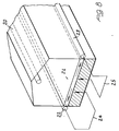
- the mentioned air delivery or distribution system comprise a plurality of pipes (20 in Fig. 5), with asymmetrical perforations aligned upward, and housed in corresponding floor channels (21 in Fig. 5), in a number of two for each way closed as a loop, as is schematically shown in Figure 4, and being protected at the top by a layer (22 in Fig. 5) of wood chips, having a poor disagregating capability, with a minimum ratio surface/volume and a high resistance against microorganisms.
- the mentioned channels are devoid of any protection grates, thereby facilitating the chips replacing operations and the removal of possible jams.
- the fans are characterized by an inherent possibility of reversing the suction and blowing flows, as it is schematically shown in Figures 6 and 7.
- the liquid particles held in the air coming from the heaps are picked up by suitable apparatus, before their inlet to the fan.
- the aerating pipe holding channels are arranged with a suitable slanted arrangement in order to facilitate the outflow of the percolated material.
- the latter after having being collected in a sealed tank, is then used for supplying the nebulizers used through the different ways and being thereby used for moistening the biomasses.
- the processing or working cell made by subdividing the mentioned bio-oxidation section, can be in turn further compartmented by providing a cloth element arranged horizontally, at a spacing of about 1 meter, above the fermenting heap.
- said heap will occupy the overall processing or working cell (Fig. 8).
- said cloth article can be automatically wound about an axis arranged along a side of the cell.
- the exhausted air from the heap are taken or picked by two manifolds, arranged within the space between the heap and cloth, and being conveyed to the floor blowing net.
- This method will allow to use, for aerating the materials being transformed, air having a high concentration of compounds adapted to facilitate a degrading of the volatile substances which are generated during the organic substance oxidation reactions.
- a suction manifold 20 for exhausted air arranged at a set height.
- a cloth 21 is horizontally arranged, in cooperation with the suction manifolds 22 and 23 comprising a floor air blowing net.
- the used materials provided that they are compatible to the intended application, as well as the contingent size and shapes can be any depending on requirements.
Landscapes
- Chemical & Material Sciences (AREA)
- Engineering & Computer Science (AREA)
- Organic Chemistry (AREA)
- Chemical Kinetics & Catalysis (AREA)
- Biochemistry (AREA)
- Biotechnology (AREA)
- Health & Medical Sciences (AREA)
- General Chemical & Material Sciences (AREA)
- Microbiology (AREA)
- Molecular Biology (AREA)
- Life Sciences & Earth Sciences (AREA)
- Manufacturing & Machinery (AREA)
- Fertilizers (AREA)
- Processing Of Solid Wastes (AREA)
Abstract
Description
Claims (8)
- A composting system for processing biomasses, characterized in that said composting system comprises at least a processing cell, including a plurality of adjoining ways, transversely of which the biomasses being processed are transferred from a supply way to an unloading way, each said ways being coupled to an air distribution assembly.
- A composting system, according to Claim 1, characterized in that each said processing cell is made of reinforced concrete dividing walls and compartmenting cloth elements.
- A composting system, according to Claims 1 and 2, characterized in that said compartmenting of the bio-oxidation section into independent volumes allows to hold suitable environment condition in the sector in which the operating steps are performed, this being obtained by differently controlling the number of air intra-exchanges by hour through the different cells comprising the system, by holding a single air inter-exchange/hour in the rest cells, i.e. the non operating cells, for a time necessary for carrying out the turning over and transferring operation being performed in an active cell, thereby providing in an active cell up to 10 air inter-exchanges by hour.
- A composting system, according to one or more of the preceding claims, characterized in that the material being transformed heaps have a constant height and a width decreasing from the supply way to the unloading way in order to overcome the biomass volume reduction.
- A composting system, according to one or more of the preceding claims, characterized in that said composting system comprises means for transferring and turning over the biomasses, said means including an adjustable length conveyor belt.
- A composting system, according to one or more of the preceding claims, characterized in that said air distribution assembly comprises a respective fan for each said way.
- A composting system, according to one or more of the preceding claims, characterized in that in said system are provided a plurality of floor channels including air distribution PVC pipes, extending along a longitudinal axis of the way, and being protected by a wood chip layer, and being devoid of covering grids.
- A composting system for processing biomasses, according to one or more of the preceding claims, and substantially as broadly disclosed and illustrated and for the intended objects.
Applications Claiming Priority (2)
| Application Number | Priority Date | Filing Date | Title |
|---|---|---|---|
| ITMI991551 | 1999-07-13 | ||
| IT1999MI001551A ITMI991551A1 (en) | 1999-07-13 | 1999-07-13 | COMPOSTING PLANT FOR BIOMASS TREATMENT |
Publications (2)
| Publication Number | Publication Date |
|---|---|
| EP1069094A2 true EP1069094A2 (en) | 2001-01-17 |
| EP1069094A3 EP1069094A3 (en) | 2001-12-05 |
Family
ID=11383337
Family Applications (1)
| Application Number | Title | Priority Date | Filing Date |
|---|---|---|---|
| EP20000113767 Withdrawn EP1069094A3 (en) | 1999-07-13 | 2000-06-29 | Composting system for processing biomasses |
Country Status (2)
| Country | Link |
|---|---|
| EP (1) | EP1069094A3 (en) |
| IT (1) | ITMI991551A1 (en) |
Cited By (1)
| Publication number | Priority date | Publication date | Assignee | Title |
|---|---|---|---|---|
| WO2002060837A3 (en) * | 2001-01-31 | 2002-09-26 | Pure Lean Hogs Inc | Composting structure |
Family Cites Families (8)
| Publication number | Priority date | Publication date | Assignee | Title |
|---|---|---|---|---|
| CH645332A5 (en) * | 1981-03-06 | 1984-09-28 | Widmer & Ernst Ag | PLANT FOR COMPOSTING MUELL. |
| WO1990008747A1 (en) * | 1989-01-26 | 1990-08-09 | Buehler Ag Maschinenfabrik | Device for repiling bulk materials |
| ES2027614T3 (en) * | 1989-03-28 | 1994-01-01 | Buehler Ag Geb | INSTALLATION OF FERMENTED WASTE FOR THE PRODUCTION OF COMPOST OF DIFFERENT DEGREES OF MATURITY. |
| US5204263A (en) * | 1991-09-27 | 1993-04-20 | Bedminster Bioconversion Corporation | Channel cover |
| DK136193A (en) * | 1993-12-06 | 1995-06-28 | Vagn Bislev | Composting plant for organic waste, and method of composting such waste |
| US5459071A (en) * | 1994-05-02 | 1995-10-17 | Bedminster Biconversion Corporation | Compost curing system |
| IT1285798B1 (en) * | 1996-10-07 | 1998-06-24 | Sct Sorain Cecchini Tecno S R | PLANT FOR THE BIOLOGICAL TREATMENT OF WASTE |
| DE19710027A1 (en) * | 1997-03-12 | 1998-09-17 | Sevar Entsorgung | Composting process for e.g. sludge from water treatment |
-
1999
- 1999-07-13 IT IT1999MI001551A patent/ITMI991551A1/en unknown
-
2000
- 2000-06-29 EP EP20000113767 patent/EP1069094A3/en not_active Withdrawn
Cited By (1)
| Publication number | Priority date | Publication date | Assignee | Title |
|---|---|---|---|---|
| WO2002060837A3 (en) * | 2001-01-31 | 2002-09-26 | Pure Lean Hogs Inc | Composting structure |
Also Published As
| Publication number | Publication date |
|---|---|
| ITMI991551A0 (en) | 1999-07-13 |
| ITMI991551A1 (en) | 2001-01-13 |
| EP1069094A3 (en) | 2001-12-05 |
Similar Documents
| Publication | Publication Date | Title |
|---|---|---|
| US20040168960A1 (en) | Methods and systems for pretreatment and processing of biomass | |
| KR101634977B1 (en) | Fuel-axes systems | |
| US20090199608A1 (en) | Composting apparatus, installation and method thereof | |
| CN107056357A (en) | Aerobic fermentation equipment | |
| Diaz et al. | Systems used in composting | |
| EP1069094A2 (en) | Composting system for processing biomasses | |
| US7883886B2 (en) | Device for cereal malting | |
| FI83506C (en) | Equipment for composting organic waste | |
| US6482643B2 (en) | Organic waste disposal equipment and systems | |
| US20080022739A1 (en) | Vertical composter with leachate retention system | |
| EP1570042B1 (en) | Methods and systems for pretreatment and processing of biomass | |
| JPH07308656A (en) | Organic waste treatment equipment | |
| JP2004035336A (en) | Organic waste composting equipment | |
| JPH07184635A (en) | Method and apparatus for fermenting organic waste | |
| EP3462846B1 (en) | A livestock housing installation | |
| JPH07241540A (en) | Fermentation processing equipment for organic materials | |
| US20070160710A1 (en) | Device for softening grain | |
| JPS605089A (en) | Vertical fermentation device | |
| JP2005538023A (en) | Upright composting device with treatment area | |
| JPH0124757B2 (en) | ||
| JP2510238Y2 (en) | Vertical multi-stage fermentation device | |
| EP0281699A1 (en) | Turned and aerated silo composting plant | |
| EP0778818A1 (en) | Window curing and odor control system | |
| JP3026413B2 (en) | Compost fermenter | |
| JPS59228997A (en) | Fermentation tank |
Legal Events
| Date | Code | Title | Description |
|---|---|---|---|
| PUAI | Public reference made under article 153(3) epc to a published international application that has entered the european phase |
Free format text: ORIGINAL CODE: 0009012 |
|
| AK | Designated contracting states |
Kind code of ref document: A2 Designated state(s): AT BE CH CY DE DK ES FI FR GB GR IE IT LI LU MC NL PT SE |
|
| AX | Request for extension of the european patent |
Free format text: AL;LT;LV;MK;RO;SI |
|
| PUAL | Search report despatched |
Free format text: ORIGINAL CODE: 0009013 |
|
| AK | Designated contracting states |
Kind code of ref document: A3 Designated state(s): AT BE CH CY DE DK ES FI FR GB GR IE IT LI LU MC NL PT SE |
|
| AX | Request for extension of the european patent |
Free format text: AL;LT;LV;MK;RO;SI |
|
| 17P | Request for examination filed |
Effective date: 20020411 |
|
| AKX | Designation fees paid |
Free format text: AT BE CH CY DE DK ES FI FR GB GR IE IT LI LU MC NL PT SE |
|
| 17Q | First examination report despatched |
Effective date: 20021025 |
|
| STAA | Information on the status of an ep patent application or granted ep patent |
Free format text: STATUS: THE APPLICATION IS DEEMED TO BE WITHDRAWN |
|
| 18D | Application deemed to be withdrawn |
Effective date: 20071231 |