EP1069051A1 - Container with anti-spill opening and respective cap - Google Patents
Container with anti-spill opening and respective cap Download PDFInfo
- Publication number
- EP1069051A1 EP1069051A1 EP00402001A EP00402001A EP1069051A1 EP 1069051 A1 EP1069051 A1 EP 1069051A1 EP 00402001 A EP00402001 A EP 00402001A EP 00402001 A EP00402001 A EP 00402001A EP 1069051 A1 EP1069051 A1 EP 1069051A1
- Authority
- EP
- European Patent Office
- Prior art keywords
- container
- plug
- liquid
- legs
- nozzle
- Prior art date
- Legal status (The legal status is an assumption and is not a legal conclusion. Google has not performed a legal analysis and makes no representation as to the accuracy of the status listed.)
- Withdrawn
Links
Images


Classifications
-
- B—PERFORMING OPERATIONS; TRANSPORTING
- B65—CONVEYING; PACKING; STORING; HANDLING THIN OR FILAMENTARY MATERIAL
- B65D—CONTAINERS FOR STORAGE OR TRANSPORT OF ARTICLES OR MATERIALS, e.g. BAGS, BARRELS, BOTTLES, BOXES, CANS, CARTONS, CRATES, DRUMS, JARS, TANKS, HOPPERS, FORWARDING CONTAINERS; ACCESSORIES, CLOSURES, OR FITTINGS THEREFOR; PACKAGING ELEMENTS; PACKAGES
- B65D51/00—Closures not otherwise provided for
- B65D51/16—Closures not otherwise provided for with means for venting air or gas
- B65D51/1672—Closures not otherwise provided for with means for venting air or gas whereby venting occurs by manual actuation of the closure or other element
- B65D51/1688—Venting occurring during initial closing or opening of the container, by means of a passage for the escape of gas between the closure and the lip of the container mouth, e.g. interrupted threads
-
- B—PERFORMING OPERATIONS; TRANSPORTING
- B65—CONVEYING; PACKING; STORING; HANDLING THIN OR FILAMENTARY MATERIAL
- B65D—CONTAINERS FOR STORAGE OR TRANSPORT OF ARTICLES OR MATERIALS, e.g. BAGS, BARRELS, BOTTLES, BOXES, CANS, CARTONS, CRATES, DRUMS, JARS, TANKS, HOPPERS, FORWARDING CONTAINERS; ACCESSORIES, CLOSURES, OR FITTINGS THEREFOR; PACKAGING ELEMENTS; PACKAGES
- B65D39/00—Closures arranged within necks or pouring openings or in discharge apertures, e.g. stoppers
- B65D39/0005—Closures arranged within necks or pouring openings or in discharge apertures, e.g. stoppers made in one piece
- B65D39/0029—Plastic closures other than those covered by groups B65D39/0011 - B65D39/0023
-
- B—PERFORMING OPERATIONS; TRANSPORTING
- B65—CONVEYING; PACKING; STORING; HANDLING THIN OR FILAMENTARY MATERIAL
- B65D—CONTAINERS FOR STORAGE OR TRANSPORT OF ARTICLES OR MATERIALS, e.g. BAGS, BARRELS, BOTTLES, BOXES, CANS, CARTONS, CRATES, DRUMS, JARS, TANKS, HOPPERS, FORWARDING CONTAINERS; ACCESSORIES, CLOSURES, OR FITTINGS THEREFOR; PACKAGING ELEMENTS; PACKAGES
- B65D41/00—Caps, e.g. crown caps or crown seals, i.e. members having parts arranged for engagement with the external periphery of a neck or wall defining a pouring opening or discharge aperture; Protective cap-like covers for closure members, e.g. decorative covers of metal foil or paper
- B65D41/02—Caps or cap-like covers without lines of weakness, tearing strips, tags, or like opening or removal devices
- B65D41/04—Threaded or like caps or cap-like covers secured by rotation
- B65D41/0407—Threaded or like caps or cap-like covers secured by rotation with integral sealing means
- B65D41/0414—Threaded or like caps or cap-like covers secured by rotation with integral sealing means formed by a plug, collar, flange, rib or the like contacting the internal surface of a container neck
-
- B—PERFORMING OPERATIONS; TRANSPORTING
- B65—CONVEYING; PACKING; STORING; HANDLING THIN OR FILAMENTARY MATERIAL
- B65D—CONTAINERS FOR STORAGE OR TRANSPORT OF ARTICLES OR MATERIALS, e.g. BAGS, BARRELS, BOTTLES, BOXES, CANS, CARTONS, CRATES, DRUMS, JARS, TANKS, HOPPERS, FORWARDING CONTAINERS; ACCESSORIES, CLOSURES, OR FITTINGS THEREFOR; PACKAGING ELEMENTS; PACKAGES
- B65D49/00—Arrangements or devices for preventing refilling of containers
-
- B—PERFORMING OPERATIONS; TRANSPORTING
- B65—CONVEYING; PACKING; STORING; HANDLING THIN OR FILAMENTARY MATERIAL
- B65D—CONTAINERS FOR STORAGE OR TRANSPORT OF ARTICLES OR MATERIALS, e.g. BAGS, BARRELS, BOTTLES, BOXES, CANS, CARTONS, CRATES, DRUMS, JARS, TANKS, HOPPERS, FORWARDING CONTAINERS; ACCESSORIES, CLOSURES, OR FITTINGS THEREFOR; PACKAGING ELEMENTS; PACKAGES
- B65D2539/00—Details relating to closures arranged within necks or pouring openings or in discharge apertures, e.g. stoppers
- B65D2539/001—Details of closures arranged within necks or pouring opening or in discharge apertures, e.g. stoppers
- B65D2539/005—Details of closures arranged within necks or pouring opening or in discharge apertures, e.g. stoppers provided with slits or gaps for increasing the elasticity
Definitions
- the present invention relates to the field of containers intended to contain a certain quantity of liquid while retaining a part of their internal volume filled with gas.
- Such containers are generally provided with a stopper shutter.
- part of the liquid which is nearby for example a drop retained by capillary action near the cap, can be projected outside the container in case of imbalance between the pressure prevailing inside said container and the ambient pressure prevailing outside.
- the liquid may then spread near the opening of the container, or even be projected onto the user's hands or clothing. This disadvantage still takes more important when the liquid is likely to cause stains, which is particularly the case when it comes to conditioning hair dye products.
- the user causes, before opening, the mixing of the dye and oxidant solution and usually shakes the conditioning to perfect this mixture.
- a chemical reaction oxidation is triggered which gives off gas, especially oxygen, which tends to increase the pressure inside conditioning.
- a male tubing threaded on which can be tightly screwed a nozzle closed distribution, and the tip of which can be broken to create a opening at the time of use, in order to pour the product on the hair.
- This breakable tip prevents the user from resealing the container by reuse of said tip, which is desirable in the since the oxidation dye does not keep after mixing. The user is therefore encouraged to discard the packaging after a first use of dye.
- the sealing means breakable which have very high hygienic qualities are not always easy to set up and use. Indeed, if their mechanical characteristics are too high, the user will tend to use a sharp blade or a pair of scissors to break the tip with a potential risk of injury and a more complex opening. At otherwise, if the mechanical characteristics of the breakable tip are weak, the tip may accidentally break during handling to which the packaging is subjected such as packaging, stacking or transport operations. We then lose a conditioning and there is a risk of staining neighboring packaging which cannot be marketed either, which causes a loss important.
- the invention proposes to provide a storage device for liquid with high hygienic qualities before use and when opening while being inexpensive and easy to use and clean.
- the device serves for the storage of liquid, in particular capillary, and comprises a container and a stopper removable, the cap being of the type comprising a gripping part and a closure part able to cooperate with a tip of the container, the said nozzle forming a passage between an interior zone of the container and the outside, a free end of the end piece forming an outlet for liquid.
- the device includes means for holding the liquid contained in the container at an axial distance from the orifice of the nozzle, the plug in closed position.
- means for fixing the plug to the container are provided, and the cap includes means for allowing a balance of pressure in the interior area of the container and the outside pressure when opening before the fastening means of the cap on the container are deactivated. This provision allows the depressurization of the container before the liquid it contains drains.
- the plug comprises a part extending substantially between the orifice of the nozzle and an opposite end of the said end piece in communication with the inner zone of the container in position closed.
- said part extends from a closed end of the plug at opposite open end and may or may not protrude from said open end. Liquid cannot stay in the front end opening, which reduces the risk of projection when the cap is opened.
- said part comprises at least one channel capable of to put in communication the interior zone of the container and a zone bounded by the plug and in communication with the outside.
- the canal, small section allows the passage of gas but slows the passage of liquid.
- said part comprises at least two tabs capable of closing at least in part the mouthpiece. Partial plugging prevents or at the very least reduces the formation of drop of liquid ready to squirt outside when the opening.
- the channel can be formed between the legs. Legs can be different in length from each other. The free ends of legs can be flat, pointed or rounded. The legs can be separated by at least one slot. Slots can be long different from each other.
- the legs are of length substantially equal to that of the nozzle. The amount of liquid close to the tip is then extremely weak and generally occurs in the form of a thin film.
- the legs are significantly longer than the tip and protrude in the inner area of the closed container.
- the amount of liquid close to the tip is again extremely weak and occurs in general in the form of a convex drop of small dimensions to the ends of the legs.
- the part extending substantially between the orifice of the nozzle and one end opposite of said tip in communication with the inner zone of the container is in shape agreement with the inner surface of the said mouthpiece.
- the shutter part can be provided either to cooperate with a free end of the nozzle, either to cooperate with one end of the nozzle close to the interior area of the container.
- the means pressure balance are able to pass through a part of retained liquid in the nozzle by capillary action.
- the device may include a tube of length greater than that of the plug, disposed inside said plug and opening out to a end in the vicinity of the orifice of the endpiece in the closed position and at the other end in the inner area of the container.
- the invention also provides a removable plug for container for storing liquid, in particular capillary.
- the cap is of the type comprising a gripping part and a part shutter capable of cooperating with a tip of the container.
- the tip forms a passage between an interior zone of the container and the exterior, a free end of the nozzle forming a liquid outlet orifice.
- the cap includes means for holding the liquid contained in the container at a distance from the orifice of the nozzle, the cap being in position closed.
- Depressurization can be performed by sampling gas under the drop of liquid.
- the device serves for the storage of liquid, in particular capillary, and comprises a container and a stopper removable.
- the cap is of the type comprising a gripping part and a closure part able to cooperate with a tip of the container, the said nozzle forming a passage between an interior zone of the container and outside.
- a free end of the endpiece forms an outlet for liquid.
- the device comprises a liquid-tight means for keep said liquid axially away from the outlet orifice and permeable to gas.
- the device serves for the storage of liquid, in particular capillary, and comprises a container and a stopper removable.
- the cap is of the type comprising a gripping part and a closure part able to cooperate with a tip of the container, the said nozzle forming a passage between an interior zone of the container and outside.
- a free end of the endpiece forms an outlet for liquid.
- the device comprises a means for spreading, by adsorption, a portion of the liquid at a distance from the orifice of the nozzle, when the device.
- the device may include surfaces on which liquid spreads during depressurization.
- the device can also include surfaces on which liquid is spread over the course of opening movement.
- the device serves for the storage of liquid, in particular capillary, and comprises a container and a stopper removable.
- the cap is of the type comprising a gripping part and a closure part able to cooperate with a tip of the container, the said nozzle forming a passage between an interior zone of the container and outside.
- a free end of the endpiece forms an outlet for liquid.
- the device comprises a gas communication means capable of take gas from the device, the liquid remaining maintained in said device.
- the gas communication means is capable of withdrawing gases elsewhere, in particular beyond the drop, for example under the drop, the container being in normal position, stopper at the top.
- the plug is intended to close off removably an opening in communication with a reserve of product formed inside a container, said cap comprising mechanical attachment means, able to cooperate with means additional attachment of the tank or an intermediate element mounted on said tank.
- Said plug comprises suitable means, in unmounted position of said plug, to oppose the establishment of the plug on said opening.
- said means comprise means elastically deformable which, in the mounted position of the plug, are in engagement inside said opening, said means elastically deformable being such that in the unassembled position of the cap, they delimit at least in part, a section greater than one inner section of said opening.
- Said elastically deformable means have, in the state free after opening a cross section greater than the diameter of opening and cannot normally enter said opening which is generally substantially cylindrical or very slightly tapered.
- the plug comprises a side wall whose a first end is closed by a transverse wall, and one of which second end is open.
- the elastically deformable means are formed of at least two legs arranged at least partially inside of the side wall and integral with the transverse wall. Legs can be in one piece with the rest of the cap.
- the legs are oriented substantially along a longitudinal axis of the side wall.
- said section of legs, greater than an inner section is formed at least in part by a free end of said legs.
- said legs are protruding from the side wall.
- said legs are separated from each other by slits.
- the legs may be of different lengths from each other.
- the free ends of the legs can be flat, pointed or rounded.
- the legs can be separated by at least one slot. Of slots can be of different length from each other. Slots may extend to the transverse wall. Slots can be short, and terminate substantially at the free end of the side wall.
- the means elastically deformable are formed of at least one skirt arranged at the less partially inside the side wall and integral with the wall transverse.
- the said legs are integral with the side wall.
- the plug can be made in one piece by molding.
- the container can also be made in one piece by molding.
- the plug is easy to manufacture and economical, does not present a risk of untimely opening during handling steps, and is easy and clean to open.
- the bottle includes a bottle body 1 and a stopper 2.
- Body 1 is made of glass or synthetic material molded and has, for example, a general shape frustoconical, for example of round, oval or other section, and ends upwards by a shoulder 3 surmounted by a tip 4 of very slightly tapered.
- the tip 4 has an upper edge 5 forming its end free, its other end connecting to the shoulder 3.
- the end piece 4 is hollow and thus forms a passage 6 connecting the interior 1a of body 1 with the exterior.
- An outlet orifice 7 of planar circular shape is formed at the upper end of passage 6 in the same plane as the upper edge 5 of the end piece 4.
- a male thread 8 is formed on the surface outside 4a of the nozzle 4.
- the plug 2 comprises a side wall 9 in the form of a skirt, very slightly frustoconical, so that its shape is consistent with the shape of the end piece 4.
- the stopper 2 further comprises a wall upper 10 circular plane and closing the upper end 9a of the side wall 9.
- the lower end 9b of the side wall 9 is opened.
- the inner surface 9c of said side wall 9 is provided with a female thread 11 able to cooperate by screwing with the male thread 8 of the end piece 4.
- the side wall 9 forms a gripping part.
- Wall upper 10 forms a closure portion.
- a sealing rim 12 of circular shape relatively sharp and of diameter corresponding to that of edge 5 so that in the closed state, said sealing rim 12 is in leaktight contact with the upper edge 5 of the end piece 4.
- the plug 2 comprises three elongated legs 13 connected to their upper end to the lower surface 1 Oa of the upper wall 10 inside the sealing rim 12. Each tab 13 extends towards the low inside the side wall 9. The lower end 14 of each tab 13 protrudes from the side wall 9 axially opposite the wall upper 10, axially understood to be in the direction of the axis of the truncated cone formed by the side wall 9.
- Each tab 13 is in the shape of an arc of a section transverse and is separated from the neighboring legs 13 by a slot 15 which extends over the entire length of the legs 13.
- a slot 15 which extends over the entire length of the legs 13.
- a channel 16 extending over the entire length of said legs 13, whatever might be expected, again, that it does not extends only over part of their length from their end lower 14.
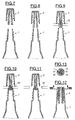
- the legs 13 have a longer length than in FIG. 1, which, at constant elasticity of the material forming them, allows a greater spacing of their lower ends 14 which can make it even more difficult attempted filling with cap 2.
- the lower ends 14 of the legs 13 are substantially flush the lower end of the side wall 9 while having, well understood, a spacing such that they cannot enter, in the free state, in orifice 7.
- This variant is particularly advantageous if it is feared that a user does not try to close the container with the cap 2 in using an instrument such as a blade or pliers to tighten the lower ends 14 of the legs 13.
- the lower ends 14 legs 13 are bevelled by being shorter on their radial edge inner than on their outer radial edge. So during a possible attempt to recap the container, if the end of a tab 13 comes into contact contact with the upper edge 5 of the end piece 4, the tab 13 will tend to escape radially outwards and therefore outside orifice 7.
- the plug 2 comprises a single leg 17 but the lower part of which is divided into several branches 18 deviating from each other downwards so that they have lower ends 19 similar to the ends lower 14 of the variants described above.
- the plug 2 comprises legs 13 of very short length, significantly less than the length axial of the plug, and between which is fixed by fitting a tube plunger 26.
- the plunger tube 26 is generally cylindrical in shape with an upper end 26a formed at an angle and arranged in the channel 16 between the legs 13, and a lower end 26b beyond the lower end 9b of the side wall 9.
- the lower end 26b of the tube 26 is disposed not in the passage 6 but in the inner zone 1a of the bottle body 1.
- the stopper 2 When the bottle is in the normal closed position, the stopper 2 being oriented upwards, the lower end 26b of the tube 26 must be locate at a level between the upper surface of the contained liquid in the body of the bottle 1 and the drop or part of liquid which, for capillarity, is likely to park in the passage 6 of the nozzle 4. This allows degassing without leaving the liquid.
- FIG. 7 we see that we come to present the plug 2 above of the bottle 1, the tabs 13 being in the free state. Then, by a downward axial movement, the plug 2 is brought closer to the orifice 7 of end piece 4, see FIG. 8.
- the tool 20 can be in the form of a plurality of fingers, at least one per leg 13 or per branch 18, capable of moving radially each leg 13 or branch 18 inwards. Fingers the tool 20 can be in a shape resembling the diaphragm of a camera so as to tighten the legs 13 which whatever their number.
- a drop 21 of said liquid generally stays near the shoulder 3 due to a phenomenon of capillarity.
- drop 21 forms in practically all cases insofar as the user shakes the container in order to cause the two components to mix.
- the volume of the drop 21 will of course depend on the physico-chemical characteristics of the liquid, such as its viscosity, its surface tension, its hydrophilicity, etc.
- the drop forms in the upper end of the stopper, in direct contact with its upper wall and can occupy a large part of the passage of the mouthpiece.
- the drop 21 is formed under the shoulder 3 and under the legs 13. Thanks to the invention, the drop is kept axially away from orifice 7.
- Channel 16 will, in general, provide the largest share of the area spreading.
- the channel 16 also forms a means for withdrawing gases from distance of the drop which forms, for the most part, in a place radially and / or axially offset from the lower end of the channel 16 formed at the free end of the legs 13.
- the free section by which the gases escape is small enough that none significant amount of liquid does not come out of the outlet during this step. It is thus possible to sample gases without projection of liquid.
- the inner surface of the end piece 5 is, in the embodiment illustrated, slightly frustoconical, orifice 7 having a diameter lower than that of the base of passage 6 near the shoulder.
- the legs 13 are forced to approach each other during said opening movement, which reduces the free cross-section for the liquid in the passage 6.
- the width of the slots 15 is reduces which causes a spin effect with a drop of part of the gout in the body 1.
- the plug 2 is completely separated from the body 1, the ends 14 of the legs 13 crossing the orifice 7.
- the legs 13 then resume their free form by occupying dimensions transverse greater than those of orifice 7, which prevents the reuse of the plug 2 on the body 1, see FIG. 17.
- the opening of the container occurs without projection of the liquid contained in the container, insofar as a possible drop of liquid is discarded areas through which overpressure gases can escape.
- the legs 13 make it possible to fetch the gases by overpressure beyond drop 21 and allow their escape after rupture of the seal and before complete separation of the plug 2 and of body 1, hence an extremely safe and clean opening of the container.
- exhaust gas causes a small drop of liquid, it spreads over surfaces provided for this purpose and which prevent projection.
- the legs 13 have been replaced by a single protrusion 22 which occupies substantially all the space formed in the end piece 4, and comes flush with the lower surface 24 of the shoulder 25 which here must be of dimension relatively large in the radial direction relative to the axis of the plug.
- This surface of the shoulder and the surface of the lower end 23 of the protuberance 22 provides an almost smooth surface on which none drop of liquid does not form. In general, only a film of liquid of very thin will remain on this surface after mixing the constituents of dye and shaking by the user.
- the rising to the top of the protuberance 22 causes only a very small amount of liquid from the film that formed, this amount tending to spread during movement along the inner wall of the passage 6, which further reduces the quantity likely to be projected during depressurization.
- the seal between the plug 2 and the body 1 can be formed either, as in the other embodiments, near the top wall of the cap or on the contrary near from the lower end 23 of the protuberance 22.
- the invention there is a stopper and a container of economical and safe and clean to use.
- the cap can be fixed by fitting or screwing.
- the risk of projection of liquid in the container is removed when used normal.
- at least part of the passage 6, a liquid tight structure to prevent its stay in said part and permeable to gas to depressurize the container.
- the combination of liquid tightness and gas permeability provides great advantages.
- the plug may, in addition, be provided with means preventing or at the very least very annoying its reuse on the container, which guarantees a single use of the product contained in the container by prompting the user to throw away said container after first use. Finally, no additional parts are added, either to the cap or to the container, both of which can be formed in one piece by molding.
Abstract
Description
La présente invention concerne le domaine des récipients destinés à contenir une certaine quantité de liquide tout en conservant une partie de leur volume interne remplie de gaz.The present invention relates to the field of containers intended to contain a certain quantity of liquid while retaining a part of their internal volume filled with gas.
De tels récipients sont généralement pourvus de bouchon d'obturation. A l'ouverture du bouchon, une partie du liquide qui se trouve à proximité, par exemple une goutte retenue par capillarité à proximité du bouchon, peut se trouver projetée à l'extérieur du récipient en cas de déséquilibre entre la pression régnant à l'intérieur dudit récipient et la pression ambiante régnant à l'extérieur. Le liquide risque alors de se répandre à proximité de l'ouverture du récipient, voire d'être projeté sur les mains ou les vêtements de l'utilisateur. Cet inconvénient prend encore plus d'importance lorsque le liquide est susceptible de provoquer des taches, ce qui est le cas notamment lorsqu'il s'agit de conditionner des produits pour teindre les cheveux.Such containers are generally provided with a stopper shutter. When the cap is opened, part of the liquid which is nearby, for example a drop retained by capillary action near the cap, can be projected outside the container in case of imbalance between the pressure prevailing inside said container and the ambient pressure prevailing outside. The liquid may then spread near the opening of the container, or even be projected onto the user's hands or clothing. This disadvantage still takes more important when the liquid is likely to cause stains, which is particularly the case when it comes to conditioning hair dye products.
A cet égard, on connaít le document EP-A-0 528 707 qui propose un conditionnement à deux flacons permettant de stocker séparément l'un de l'autre deux produits, notamment liquides, et de les mélanger au moment de leur utilisation. Ce conditionnement est conçu pour stocker séparément, d'une part une solution de colorant destinée à une teinture pour cheveux, et d'autre part l'oxydant qui est nécessaire à la mise en oeuvre de la solution de colorant. Pour teindre les cheveux avec des "colorants d'oxydation", il faut en effet faire développer le colorant sur les cheveux en ajoutant un oxydant, par exemple de l'eau oxygénée, sur le colorant au moment où il est mis en place sur les cheveux. La présentation en double flaconnage facilite donc considérablement la mise en oeuvre de la coloration des cheveux.In this regard, we know the document EP-A-0 528 707 which proposes a packaging with two bottles allowing one to be stored separately on the other, two products, especially liquids, and mix them with time of use. This packaging is designed to store separately, on the one hand a dye solution intended for a dye for hair, and on the other hand the oxidant which is necessary for setting dye solution artwork. To dye hair with "oxidation dyes", it is necessary to develop the dye on hair by adding an oxidant, for example hydrogen peroxide, on the dye when it is put in place on the hair. The presentation in double bottles therefore considerably facilitates the implementation of hair coloring.
L'utilisateur provoque, avant ouverture, le mélange de la solution de colorant et de l'oxydant et secoue en général le conditionnement pour parfaire ce mélange. Une réaction chimique d'oxydation se déclenche qui provoque un dégagement gazeux, notamment d'oxygène, qui tend à faire augmenter la pression à l'intérieur du conditionnement. Au sommet du flacon est prévue une tubulure mâle filetée sur laquelle peut être vissé de manière étanche un embout de distribution fermé, et dont la pointe peut être cassée pour la création d'une ouverture au moment de l'utilisation, en vue de verser le produit sur les cheveux. Cette pointe cassable empêche l'utilisateur de reboucher le récipient par réutilisation de ladite pointe, ce qui est souhaitable dans la mesure où le colorant d'oxydation ne se conserve pas après mélange. L'utilisateur est donc incité à jeter le conditionnement après une première utilisation du colorant.The user causes, before opening, the mixing of the dye and oxidant solution and usually shakes the conditioning to perfect this mixture. A chemical reaction oxidation is triggered which gives off gas, especially oxygen, which tends to increase the pressure inside conditioning. At the top of the bottle is provided a male tubing threaded on which can be tightly screwed a nozzle closed distribution, and the tip of which can be broken to create a opening at the time of use, in order to pour the product on the hair. This breakable tip prevents the user from resealing the container by reuse of said tip, which is desirable in the since the oxidation dye does not keep after mixing. The user is therefore encouraged to discard the packaging after a first use of dye.
Toutefois, il s'avère qu'une goutte de colorant se trouve généralement à proximité immédiate de la pointe cassable au moment de l'ouverture car l'extrémité interne de l'embout de distribution est de forme pointue qui tend à retenir une goutte de colorant par capillarité et que l'utilisateur a en général secoué le conditionnement, ce qui a provoqué la formation de cette goutte. Ainsi, lorsque l'utilisateur casse la pointe pour ouvrir le conditionnement, la goutte présente à proximité immédiate risque d'être projetée sur une surface extérieure du conditionnement, sur les mains de l'utilisateur ou pire encore sur ses vêtements qu'elle risque de tacher irrémédiablement. Ce phénomène est d'autant plus marqué que l'utilisateur a provoqué le mélange des deux constituants du colorant un certain temps avant d'en provoquer l'ouverture, par exemple s'il s'est lavé les cheveux entre ces deux opérations. En effet, la réaction chimique entre les deux constituants aura alors provoqué une élévation de pression d'où un différentiel de pression plus important entre l'intérieur du conditionnement et l'atmosphère ambiante lors de l'ouverture.However, it turns out that a drop of dye is found generally in the immediate vicinity of the breakable tip at the time of the opening because the internal end of the dispensing nozzle is shaped pointed which tends to retain a drop of dye by capillarity and that the user generally shook the packaging, which caused the formation of this drop. So when the user breaks the tip to open the packaging, the drop present in the immediate vicinity risk of being projected onto an external surface of the packaging, onto hands of the user or even worse on his clothes which he risks stain beyond repair. This phenomenon is all the more marked since the user caused the two constituents of the dye to mix some time before opening it, for example if it has washed the hair between these two operations. Indeed, the chemical reaction between the two constituents will then have caused an increase in pressure where a greater pressure differential between the interior of the conditioning and the ambient atmosphere upon opening.
Par ailleurs, on s'est aperçu que les moyens d'obturation cassables qui présentent de très hautes qualités d'hygiène ne sont pas toujours faciles à mettre en oeuvre et à utiliser. En effet, si leurs caractéristiques mécaniques sont trop élevées, l'utilisateur tendra à utiliser une lame coupante ou une paire de ciseaux pour casser la pointe avec un risque potentiel de blessure et une ouverture plus complexe. Au contraire, si les caractéristiques mécaniques de la pointe cassable sont faibles, la pointe peut se casser de façon accidentelle lors des manipulations auxquelles le conditionnement est soumis telles que des opérations d'emballage, de gerbage ou de transport. On perd alors un conditionnement et on risque de tacher les conditionnements voisins qui ne pourront pas non plus être commercialisés, ce qui provoque une perte importante.In addition, we realized that the sealing means breakable which have very high hygienic qualities are not always easy to set up and use. Indeed, if their mechanical characteristics are too high, the user will tend to use a sharp blade or a pair of scissors to break the tip with a potential risk of injury and a more complex opening. At otherwise, if the mechanical characteristics of the breakable tip are weak, the tip may accidentally break during handling to which the packaging is subjected such as packaging, stacking or transport operations. We then lose a conditioning and there is a risk of staining neighboring packaging which cannot be marketed either, which causes a loss important.
L'invention propose de fournir un dispositif de stockage de liquide présentant de hautes qualités d'hygiène avant utilisation et lors de l'ouverture tout en étant bon marché et d'utilisation facile et propre.The invention proposes to provide a storage device for liquid with high hygienic qualities before use and when opening while being inexpensive and easy to use and clean.
Le dispositif, selon un aspect de l'invention, sert au stockage de liquide, notamment capillaire, et comprend un récipient et un bouchon amovible, le bouchon étant du type comprenant une partie de préhension et une partie d'obturation apte à coopérer avec un embout du récipient, le dit embout formant un passage entre une zone intérieure du récipient et l'extérieur, une extrémité libre de l'embout formant un orifice de sortie de liquide. Le dispositif comprend un moyen pour maintenir le liquide contenu dans le récipient à distance axiale de l'orifice de l'embout, le bouchon étant en position fermée.The device, according to one aspect of the invention, serves for the storage of liquid, in particular capillary, and comprises a container and a stopper removable, the cap being of the type comprising a gripping part and a closure part able to cooperate with a tip of the container, the said nozzle forming a passage between an interior zone of the container and the outside, a free end of the end piece forming an outlet for liquid. The device includes means for holding the liquid contained in the container at an axial distance from the orifice of the nozzle, the plug in closed position.
Ainsi, on prévient un épanchement brusque du liquide hors du récipient lors de l'ouverture lorsque la pression régnant dans la zone intérieure du récipient est supérieure à la pression extérieure, le récipient étant rempli en partie de liquide et en partie de gaz. Le liquide est maintenu à distance de l'orifice de l'embout.Thus, a sudden outpouring of the liquid out of the container when opening when the pressure in the area inside the container is higher than the outside pressure the container being partly filled with liquid and partly with gas. The liquid is kept away from the orifice of the nozzle.
Avantageusement, des moyens de fixation du bouchon sur le récipient sont prévus, et le bouchon comprend des moyens pour permettre un équilibre de la pression dans la zone intérieure du récipient et de la pression à l'extérieur lors de l'ouverture avant que les moyens de fixation du bouchon sur le récipient soient désactivés. Cette disposition permet la dépressurisation du récipient avant écoulement du liquide qu'il contient.Advantageously, means for fixing the plug to the container are provided, and the cap includes means for allowing a balance of pressure in the interior area of the container and the outside pressure when opening before the fastening means of the cap on the container are deactivated. This provision allows the depressurization of the container before the liquid it contains drains.
Avantageusement, le bouchon comprend une partie s'étendant sensiblement entre l'orifice de l'embout et une extrémité opposée du dit embout en communication avec la zone intérieure du récipient en position fermée. En d'autres termes, ladite partie s'étend d'une extrémité fermée du bouchon à une extrémité opposée ouverte et peut dépasser ou non de ladite extrémité ouverte. Le liquide ne peut séjourner dans l'embout avant l'ouverture, ce qui réduit le risque de projection à l'ouverture du bouchon.Advantageously, the plug comprises a part extending substantially between the orifice of the nozzle and an opposite end of the said end piece in communication with the inner zone of the container in position closed. In other words, said part extends from a closed end of the plug at opposite open end and may or may not protrude from said open end. Liquid cannot stay in the front end opening, which reduces the risk of projection when the cap is opened.
De préférence, la dite partie comprend au moins un canal apte à mettre en communication la zone intérieure du récipient et une zone délimitée par le bouchon et en communication avec l'extérieur. Le canal, de faible section, permet le passage de gaz mais freine le passage du liquide.Preferably, said part comprises at least one channel capable of to put in communication the interior zone of the container and a zone bounded by the plug and in communication with the outside. The canal, small section, allows the passage of gas but slows the passage of liquid.
Dans un mode de réalisation de l'invention, la dite partie comprend au moins deux pattes aptes à obturer au moins en partie l'embout. L'obturation partielle de l'embout prévient ou à tout le moins réduit la formation de goutte de liquide prête à gicler à l'extérieur lors de l'ouverture. Le canal peut être formé entre les pattes. Les pattes peuvent être de longueur différentes les unes des autres. Les extrémités libres des pattes peuvent être plates, pointues ou arrondies. Les pattes peuvent être séparées par au moins une fente. Des fentes peuvent être de longueur différentes les unes des autres.In one embodiment of the invention, said part comprises at least two tabs capable of closing at least in part the mouthpiece. Partial plugging prevents or at the very least reduces the formation of drop of liquid ready to squirt outside when the opening. The channel can be formed between the legs. Legs can be different in length from each other. The free ends of legs can be flat, pointed or rounded. The legs can be separated by at least one slot. Slots can be long different from each other.
Dans un mode de réalisation de l'invention, les pattes sont de longueur sensiblement égale à celle de l'embout. La quantité de liquide proche de l'embout est alors extrêmement faible et se présente en général sous la forme d'un film mince.In one embodiment of the invention, the legs are of length substantially equal to that of the nozzle. The amount of liquid close to the tip is then extremely weak and generally occurs in the form of a thin film.
Dans un autre mode de réalisation de l'invention, les pattes sont de longueur sensiblement supérieure à celle de l'embout et font saillie dans la zone intérieure du récipient à l'état fermé. La quantité de liquide proche de l'embout est là encore extrêmement faible et se présente en général sous la forme d'une goutte convexe de faibles dimensions à l'extrémité des pattes.In another embodiment of the invention, the legs are significantly longer than the tip and protrude in the inner area of the closed container. The amount of liquid close to the tip is again extremely weak and occurs in general in the form of a convex drop of small dimensions to the ends of the legs.
Dans un autre mode de réalisation de l'invention, la partie s'étendant sensiblement entre l'orifice de l'embout et une extrémité opposée du dit embout en communication avec la zone intérieure du récipient est en concordance de forme avec la surface intérieure du dit embout. La partie d'obturation peut être prévue soit pour coopérer avec une extrémité libre de l'embout, soit pour coopérer avec une extrémité de l'embout proche de la zone intérieure du récipient. In another embodiment of the invention, the part extending substantially between the orifice of the nozzle and one end opposite of said tip in communication with the inner zone of the container is in shape agreement with the inner surface of the said mouthpiece. The shutter part can be provided either to cooperate with a free end of the nozzle, either to cooperate with one end of the nozzle close to the interior area of the container.
Dans un mode de réalisation de l'invention, les moyens d'équilibre de pression sont aptes à traverser une partie de liquide retenue dans l'embout par capillarité.In one embodiment of the invention, the means pressure balance are able to pass through a part of retained liquid in the nozzle by capillary action.
Le dispositif peut comprendre un tube de longueur supérieure à celle du bouchon, disposé à l'intérieur du dit bouchon et débouchant à une extrémité au voisinage de l'orifice de l'embout en position fermée et à l'autre extrémité dans la zone intérieure du récipient.The device may include a tube of length greater than that of the plug, disposed inside said plug and opening out to a end in the vicinity of the orifice of the endpiece in the closed position and at the other end in the inner area of the container.
L'invention propose également un bouchon amovible pour récipient servant au stockage de liquide, notamment capillaire. Le bouchon est du type comprenant une partie de préhension et une partie d'obturation apte à coopérer avec un embout du récipient. L'embout forme un passage entre une zone intérieure du récipient et l'extérieur, une extrémité libre de l'embout formant un orifice de sortie de liquide. Le bouchon comprend un moyen pour maintenir le liquide contenu dans le récipient à distance de l'orifice de l'embout, le bouchon étant en position fermée.The invention also provides a removable plug for container for storing liquid, in particular capillary. The cap is of the type comprising a gripping part and a part shutter capable of cooperating with a tip of the container. The tip forms a passage between an interior zone of the container and the exterior, a free end of the nozzle forming a liquid outlet orifice. The cap includes means for holding the liquid contained in the container at a distance from the orifice of the nozzle, the cap being in position closed.
En cas de présence d'une goutte de liquide à proximité du bouchon, la dite goutte se trouve écartée de l'embout ce qui permet une dépressurisation du récipient sans projection de liquide susceptible de se répandre sur des surfaces extérieures du récipient sur les mains d'un utilisateur, sur ses vêtements, etc. La dépressurisation peut être effectuée par prélèvement de gaz sous la goutte de liquide.If there is a drop of liquid near the plug, said drop is spaced from the tip which allows a depressurization of the container without projection of liquid liable to spread on exterior surfaces of the container on the hands of a user, on his clothes, etc. Depressurization can be performed by sampling gas under the drop of liquid.
Le dispositif, selon un aspect de l'invention, sert au stockage de liquide, notamment capillaire, et comprend un récipient et un bouchon amovible. Le bouchon est du type comprenant une partie de préhension et une partie d'obturation apte à coopérer avec un embout du récipient, le dit embout formant un passage entre une zone intérieure du récipient et l'extérieur. Une extrémité libre de l'embout forme un orifice de sortie de liquide. Le dispositif comprend un moyen étanche au liquide pour maintenir ledit liquide à distance axialement de l'orifice de sortie et perméable au gaz.The device, according to one aspect of the invention, serves for the storage of liquid, in particular capillary, and comprises a container and a stopper removable. The cap is of the type comprising a gripping part and a closure part able to cooperate with a tip of the container, the said nozzle forming a passage between an interior zone of the container and outside. A free end of the endpiece forms an outlet for liquid. The device comprises a liquid-tight means for keep said liquid axially away from the outlet orifice and permeable to gas.
Le dispositif, selon un aspect de l'invention, sert au stockage de liquide, notamment capillaire, et comprend un récipient et un bouchon amovible. Le bouchon est du type comprenant une partie de préhension et une partie d'obturation apte à coopérer avec un embout du récipient, le dit embout formant un passage entre une zone intérieure du récipient et l'extérieur. Une extrémité libre de l'embout forme un orifice de sortie de liquide. Le dispositif comprend un moyen pour étaler, par adsorption, une portion du liquide à distance de l'orifice de l'embout, lors de l'ouverture du dispositif.The device, according to one aspect of the invention, serves for the storage of liquid, in particular capillary, and comprises a container and a stopper removable. The cap is of the type comprising a gripping part and a closure part able to cooperate with a tip of the container, the said nozzle forming a passage between an interior zone of the container and outside. A free end of the endpiece forms an outlet for liquid. The device comprises a means for spreading, by adsorption, a portion of the liquid at a distance from the orifice of the nozzle, when the device.
Le dispositif peut comprendre des surfaces sur lesquelles du liquide s'étale lors de la dépressurisation. Le dispositif peut, en outre, comprendre des surfaces sur lesquelles du liquide s'étale au cours du mouvement d'ouverture.The device may include surfaces on which liquid spreads during depressurization. The device can also include surfaces on which liquid is spread over the course of opening movement.
Le dispositif, selon un aspect de l'invention, sert au stockage de liquide, notamment capillaire, et comprend un récipient et un bouchon amovible. Le bouchon est du type comprenant une partie de préhension et une partie d'obturation apte à coopérer avec un embout du récipient, le dit embout formant un passage entre une zone intérieure du récipient et l'extérieur. Une extrémité libre de l'embout forme un orifice de sortie de liquide. Le dispositif comprend un moyen de communication de gaz apte à prélever des gaz contenus dans le dispositif, le liquide restant maintenu dans ledit dispositif.The device, according to one aspect of the invention, serves for the storage of liquid, in particular capillary, and comprises a container and a stopper removable. The cap is of the type comprising a gripping part and a closure part able to cooperate with a tip of the container, the said nozzle forming a passage between an interior zone of the container and outside. A free end of the endpiece forms an outlet for liquid. The device comprises a gas communication means capable of take gas from the device, the liquid remaining maintained in said device.
Une goutte de liquide se formant généralement à proximité de l'orifice de sortie, le moyen de communication de gaz est apte à prélever des gaz ailleurs, notamment au delà de la goutte, par exemple sous la goutte, le récipient étant en position normale, bouchon en haut. Le prélèvement de gaz à distance de la goutte, en particulier à distance radiale et/ou axiale, permet d'éviter la projection.A drop of liquid usually forming near the outlet orifice, the gas communication means is capable of withdrawing gases elsewhere, in particular beyond the drop, for example under the drop, the container being in normal position, stopper at the top. The gas sampling at a distance from the drop, in particular at a distance radial and / or axial, prevents projection.
On peut prévoir d'interdire ou tout au moins de gêner le rebouchage du récipient après une première ouverture par l'utilisateur.We can plan to prohibit or at least hinder the recapping of the container after a first opening by the user.
Le bouchon, selon un aspect de l'invention, est destiné à obturer de manière amovible une ouverture en communication avec une réserve de produit formée à l'intérieur d'un récipient, ledit bouchon comprenant des moyens d'accrochage mécaniques, aptes à coopérer avec des moyens d'accrochage complémentaires du réservoir ou d'un élément intermédiaire monté sur ledit réservoir. Ledit bouchon comprend des moyens aptes, en position non montée dudit bouchon, à s'opposer à la mise en place du bouchon sur ladite ouverture.The plug, according to one aspect of the invention, is intended to close off removably an opening in communication with a reserve of product formed inside a container, said cap comprising mechanical attachment means, able to cooperate with means additional attachment of the tank or an intermediate element mounted on said tank. Said plug comprises suitable means, in unmounted position of said plug, to oppose the establishment of the plug on said opening.
Ainsi, un utilisateur se trouve empêché de reboucher le récipient avec le bouchon, ce qui constitue une très forte incitation à jeter le dit récipient, ce qui est souhaité dans le cas de produits susceptibles de se dégrader après ouverture et mise à l'atmosphère ambiante.Thus, a user is prevented from recapping the container with the cap, which is a very strong incentive to throw away the said container, which is desired in the case of products liable to degrade after opening and placing in the ambient atmosphere.
Avantageusement, lesdits moyens comprennent des moyens élastiquement déformables qui, en position montée du bouchon, sont en engagement à l'intérieur de ladite ouverture, lesdits moyens élastiquement déformables étant tels qu'en position non montée du bouchon, ils délimitent au moins en partie, une section supérieure à une section intérieure de ladite ouverture.Advantageously, said means comprise means elastically deformable which, in the mounted position of the plug, are in engagement inside said opening, said means elastically deformable being such that in the unassembled position of the cap, they delimit at least in part, a section greater than one inner section of said opening.
Les dits moyens élastiquement déformables présentent, à l'état libre après ouverture une section transversale supérieure au diamètre de l'ouverture et ne peuvent normalement pas entrer dans la dite ouverture qui est généralement de forme sensiblement cylindrique ou très légèrement tronconique.Said elastically deformable means have, in the state free after opening a cross section greater than the diameter of opening and cannot normally enter said opening which is generally substantially cylindrical or very slightly tapered.
Avantageusement, le bouchon comprend une paroi latérale dont une première extrémité est obturée par une paroi transversale, et dont une seconde extrémité est ouverte.Advantageously, the plug comprises a side wall whose a first end is closed by a transverse wall, and one of which second end is open.
De préférence, les moyens élastiquement déformables sont formés d'au moins deux pattes disposées au moins en partie à l'intérieur de la paroi latérale et solidaires de la paroi transversale. Les pattes peuvent être monobloc avec le reste du bouchon.Preferably, the elastically deformable means are formed of at least two legs arranged at least partially inside of the side wall and integral with the transverse wall. Legs can be in one piece with the rest of the cap.
Dans un mode de réalisation de l'invention, les pattes sont orientées sensiblement selon un axe longitudinal de la paroi latérale.In one embodiment of the invention, the legs are oriented substantially along a longitudinal axis of the side wall.
Dans un mode de réalisation de l'invention, la dite section des pattes, supérieure à une section intérieure est formée au moins en partie par une extrémité libre des dites pattes.In one embodiment of the invention, said section of legs, greater than an inner section is formed at least in part by a free end of said legs.
Avantageusement, les dites pattes sont en saillie par rapport à la paroi latérale.Advantageously, said legs are protruding from the side wall.
Dans un mode de réalisation de l'invention, les dites pattes sont séparées les unes des autres par des fentes.In one embodiment of the invention, said legs are separated from each other by slits.
Les pattes peuvent être de longueur différentes les unes des autres. Les extrémités libres des pattes peuvent être plates, pointues ou arrondies. Les pattes peuvent être séparées par au moins une fente. Des fentes peuvent être de longueur différentes les unes des autres. Des fentes peuvent s'étendre jusqu'à la paroi transversale. Des fentes peuvent être courtes, et se terminer sensiblement au niveau de l'extrémité libre de la paroi latérale.The legs may be of different lengths from each other. The free ends of the legs can be flat, pointed or rounded. The legs can be separated by at least one slot. Of slots can be of different length from each other. Slots may extend to the transverse wall. Slots can be short, and terminate substantially at the free end of the side wall.
Dans un autre mode de réalisation de l'invention, les moyens élastiquement déformables sont formés d'au moins une jupe disposée au moins en partie à l'intérieur de la paroi latérale et solidaire de la paroi transversale.In another embodiment of the invention, the means elastically deformable are formed of at least one skirt arranged at the less partially inside the side wall and integral with the wall transverse.
Dans un autre mode de réalisation de l'invention, les dites pattes sont solidaires de la paroi latérale.In another embodiment of the invention, the said legs are integral with the side wall.
Le bouchon peut être réalisé d'une seule pièce par moulage. Le récipient peut aussi être réalisé d'une seule pièce par moulage.The plug can be made in one piece by molding. The container can also be made in one piece by molding.
On voit donc que le bouchon est de fabrication aisée et économique, ne présente pas de risque d'ouverture intempestive lors d'étapes de manutention, et est d'ouverture aisée et propre.So we see that the plug is easy to manufacture and economical, does not present a risk of untimely opening during handling steps, and is easy and clean to open.
La présente invention sera mieux comprise à l'étude de la
description détaillée de quelques modes de réalisation pris à titre
d'exemples nullement limitatifs et illustrés par les dessins annexés, sur
lesquels :
Comme on peut le voir sur les figures, le flacon comprend un
corps de flacon 1 et un bouchon 2. Le corps 1 est réalisé en verre ou en
matériau synthétique moulé et présente, par exemple, une forme générale
tronconique, par exemple de section ronde, ovale ou autre, et se termine
vers le haut par un épaulement 3 surmonté d'un embout 4 de forme très
légèrement tronconique.As can be seen in the figures, the bottle includes a
L'embout 4 présente un bord supérieur 5 formant son extrémité
libre, son autre extrémité se raccordant à l'épaulement 3. L'embout 4 est
creux et forme ainsi un passage 6 mettant en communication l'intérieur 1a
du corps 1 avec l'extérieur. Un orifice de sortie 7 de forme circulaire plane
est formé à l'extrémité supérieure du passage 6 dans le même plan que le
bord supérieur 5 de l'embout 4. Un filetage mâle 8 est formé sur la surface
extérieure 4a de l'embout 4.The
Le bouchon 2 comprend une paroi latérale 9 en forme de jupe,
très légèrement tronconique, de façon que sa forme soit concordante avec
la forme de l'embout 4. Le bouchon 2 comprend en outre une paroi
supérieure 10 plane circulaire et fermant l'extrémité supérieure 9a de la
paroi latérale 9. L'extrémité inférieure 9b de la paroi latérale 9 est
ouverte. La surface intérieure 9c de ladite paroi latérale 9 est pourvue d'un
filetage femelle 11 apte à coopérer par vissage avec le filetage mâle 8 de
l'embout 4. La paroi latérale 9 forme une partie de préhension. La paroi
supérieure 10 forme une partie d'obturation.The
Sur la surface inférieure 10a de la paroi supérieure 10, du côté de
la paroi latérale 9, est formé un rebord d'étanchéité 12 de forme circulaire
relativement acéré et de diamètre correspondant à celui du bord 5 de façon
qu'à l'état fermé, ledit rebord d'étanchéité 12 soit en contact étanche avec
le bord supérieur 5 de l'embout 4.On the
Le bouchon 2 comprend trois pattes 13 allongées se rattachant à
leur extrémité supérieure à la surface inférieure 1 Oa de la paroi supérieure
10 à l'intérieur du rebord d'étanchéité 12. Chaque patte 13 s'étend vers le
bas à l'intérieur de la paroi latérale 9. L'extrémité inférieure 14 de chaque
patte 13 dépasse de la paroi latérale 9 axialement à l'opposé de la paroi
supérieure 10, axialement s'entendant comme étant dans le sens de l'axe du
tronc de cône formé par la paroi latérale 9.The
Chaque patte 13 est en forme d'arc de cercle en section
transversale et est séparée des pattes 13 voisines par une fente 15 qui
s'étend sur toute la longueur des pattes 13. A titre de variante, on pourrait
concevoir qu'une ou plusieurs fentes 15 ne s'étendent que sur une partie de
la longueur des pattes 13 à partir de leur extrémité inférieure 14. Il
conviendrait toutefois de conserver une des fentes 15 s'étendant jusqu'à
proximité de la paroi supérieure 10 pour une raison qui sera exposée ci-après. Each
Entre les pattes 13 est défini un canal 16 s'étendant sur toute la
longueur desdites pattes 13, quoi qu'on pourrait prévoir, là encore, qu'il ne
s'étende que sur une partie de leur longueur à partir de leur extrémité
inférieure 14.Between the
Sur la figure 1, on voit que le bouchon 2 est séparé du corps 1. Les
pattes 13, qui sont relativement souples dans le sens transversal, sont donc
représentées à l'état libre. Dans cet état libre, leurs extrémités inférieures
14 s'inscrivent dans un cercle fictif dont le diamètre est supérieur à celui
de l'orifice 7 de l'embout 4. Ainsi, un utilisateur qui a dévissé le bouchon 2
et l'a complètement séparé de l'embout 4 éprouve de grandes difficultés à
remettre le bouchon 2 sur ledit embout 4, car les extrémités 14 des pattes
13 occupent un diamètre plus important que celui offert par l'orifice 7 du
passage 6. L'utilisateur est donc très fortement incité à ne pas reboucher le
récipient avec le bouchon 2.In Figure 1, we see that the
Dans la variante illustrée sur la figure 3, les pattes 13 présentent
une longueur plus élevée que sur la figure 1, ce qui, à élasticité constante
du matériau les formant, permet un écartement plus élevé de leurs
extrémités inférieures 14, ce qui peut rendre encore plus difficile la
tentative de rebouchage avec le bouchon 2.In the variant illustrated in Figure 3, the
Au contraire, dans la variante illustrée sur la figure 4, les
extrémités inférieures 14 des pattes 13 affleurent sensiblement
l'extrémité inférieure de la paroi latérale 9 tout en présentant, bien
entendu, un écartement tel qu'elles ne puissent rentrer, à l'état libre, dans
l'orifice 7. Cette variante est particulièrement avantageuse si l'on craint
qu'un utilisateur ne tente de refermer le récipient avec le bouchon 2 en
s'aidant d'un instrument tel qu'une lame ou une pince pour venir resserrer
les extrémités inférieures 14 des pattes 13. Les extrémités inférieures 14
des pattes 13 sont biseautées en étant plus courtes sur leur bord radial
intérieur que sur leur bord radial extérieur. Ainsi, au cours d'une possible
tentative de rebouchage du récipient, si l'extrémité d'une patte 13 vient en
contact avec le bord supérieur 5 de l'embout 4, la patte 13 aura tendance à
s'échapper radialement vers l'extérieur et par conséquent en-dehors de
l'orifice 7.On the contrary, in the variant illustrated in FIG. 4, the
lower ends 14 of the
Dans la variante illustrée sur la figure 5, le bouchon 2 comprend
une unique patte 17 mais dont la partie inférieure se divise en plusieurs
branches 18 s'écartant les unes des autres vers le bas de façon qu'elles
présentent des extrémités inférieures 19 semblables aux extrémités
inférieures 14 des variantes décrites ci-dessus. On pourrait encore prévoir
une patte 13 et une patte 17 à deux branches 18, ou bien deux pattes 17 à
deux branches 18.In the variant illustrated in FIG. 5, the
Dans la variante illustrée sur la figure 6, le bouchon 2 comprend
des pattes 13 de très faible longueur, nettement inférieure à la longueur
axiale du bouchon, et entre lesquelles est fixé par emmanchement un tube
plongeur 26. Le tube plongeur 26 est de forme généralement cylindrique
avec une extrémité supérieure 26a formée en biais et disposée dans le
canal 16 entre les pattes 13, et une extrémité inférieure 26b au-delà de
l'extrémité inférieure 9b de la paroi latérale 9. Ainsi, à l'état fermé,
l'extrémité inférieure 26b du tube 26 est disposée non pas dans le passage
6 mais dans la zone intérieure 1a du corps de flacon 1. Lors de l'ouverture,
après rupture de l'étanchéité formée entre le rebord 12 et le bord supérieur
5 de l'embout 4, avant désengagement total des filets 8 et 11, les gaz en
surpression dans la zone intérieure la du corps de flacon 1 s'échappent en
passant par l'intérieur du tube 26 puis par une ou plusieurs des fentes 15
séparant les pattes 13 puis en redescendant entre l'embout 4 et la paroi
latérale 9. L'extrémité supérieure 26a coupée en biseau garantit une
communication entre l'intérieur du tube 26 et au moins l'une des fentes 15.
Si une goutte de liquide est présente dans le passage 6, la décompression
des gaz préalablement au désengagement des filets 8 et 11 garantit une
absence de projection grâce à l'égalisation des pressions interne et
externe. Lorsque le flacon est en position normale fermée, le bouchon 2
étant orienté vers le haut, l'extrémité inférieure 26b du tube 26 doit se
situer à un niveau compris entre la surface supérieure du liquide contenu
dans le corps du flacon 1 et la goutte ou partie de liquide qui, par
capillarité, est susceptible de stationner dans le passage 6 de l'embout 4.
On permet ainsi un dégazage sans sortie de liquide.In the variant illustrated in FIG. 6, the
Dans une variante, on pourrait encore prévoir que les pattes 13,
occupant un espace radial réduit, soient disposées à l'intérieur du tube 26
dont l'extrémité supérieure 26a sera toujours taillée en biseau pour
permettre une communication de gaz.In a variant, one could also provide that the
Les étapes de bouchage du récipient sont illustrées sur les figures 7 à 12. Ces étapes de bouchage ont lieu dans l'unité de production du fabricant du produit concerné, et ne sont pas matériellement à la portée du consommateur, à son domicile.The steps for plugging the container are illustrated on the Figures 7 to 12. These capping steps take place in the production unit of the manufacturer of the product concerned, and are not physically available of the consumer, at his home.
Sur la figure 7, on voit que l'on vient présenter le bouchon 2 au-dessus
du flacon 1, les pattes 13 étant à l'état libre. Puis, par un
mouvement axial vers le bas, on rapproche le bouchon 2 de l'orifice 7 de
l'embout 4, voir figure 8. A l'aide d'un outil 20, on provoque le
rapprochement mutuel des pattes 13 de façon qu'elles s'inscrivent dans un
cercle fictif de diamètre inférieur à celui de l'ouverture 7 du passage 6,
voir figure 9. L'outil 20 peut se présenter sous la forme d'une pluralité de
doigts, au moins un par patte 13 ou par branche 18, apte à déplacer
radialement chaque patte 13 ou branche 18 vers l'intérieur. Les doigts de
l'outil 20 peuvent se présenter sous une forme ressemblant au diaphragme
d'un appareil photographique de façon à venir resserrer les pattes 13 quel
que soit leur nombre.In Figure 7, we see that we come to present the
Sur la figure 10, on voit qu'après resserrement des pattes 13 par
l'outil 20, on poursuit le mouvement axial vers le bas du bouchon 2 en
présentant l'extrémité 14 des pattes 13 dans l'orifice 7 et en y faisant entrer
légèrement lesdites extrémités 14.In Figure 10, we see that after tightening the
Sur la figure 11, on voit que l'on retire l'outil 20, les pattes 13
étant retenues dans la partie supérieure du passage 6. On reprend alors le
mouvement axial vers le bas jusqu'à l'engagement mutuel des filets 8 et 11.
On entraíne le bouchon 2 en rotation pour provoquer le vissage jusqu'à
l'obturation complète et étanche comme illustré sur la figure 12.In Figure 11, we see that we remove the
Les extrémités 14 des pattes 13 sont alors en saillie à l'intérieur
du corps 1 en-dessous de l'épaulement 3.The ends 14 of the
Le fonctionnement du dispositif à l'ouverture est illustré sur les
figures 14 à 17. Lorsque le récipient est rempli au moins partiellement de
liquide, une goutte 21 dudit liquide séjourne en général à proximité de
l'épaulement 3 en raison d'un phénomène de capillarité. Dans le cas d'un
applicateur de colorant capillaire, la goutte 21 se forme dans pratiquement
tous les cas dans la mesure où l'utilisateur secoue le récipient en vue de
provoquer le mélange des deux composants. On peut se référer au
document EP-A-0 528 707 pour une description plus complète d'un
conditionnement à deux compartiments. Le volume de la goutte 21
dépendra bien entendu des caractéristiques physico-chimiques du liquide,
telles que sa viscosité, sa tension de surface, son hydrophilie, etc.The operation of the device upon opening is illustrated on the
Figures 14 to 17. When the container is at least partially filled with
liquid, a
Dans le cas d'un bouchon classique, dépourvu de pattes 13, la
goutte se forme dans l'extrémité supérieure du bouchon, en contact direct
avec sa paroi supérieure et peut occuper une grande partie du passage de
l'embout.In the case of a conventional plug, devoid of
Comme on le voit sur la figure 14, avec le bouchon 2 conforme à
l'invention, la goutte 21 se forme sous l'épaulement 3 et sous les pattes
13.Grâce à l'invention, la goutte est maintenue à distance axialement de
l'orifice 7.As seen in Figure 14, with the
Lorsqu'on dévisse le bouchon 2, comme illustré sur la figure 15,
ledit bouchon 2 remonte légèrement, ce qui provoque la séparation du
rebord d'étanchéité 12 d'avec le bord supérieur 5 de l'embout 4 et la
rupture de l'étanchéité.When you unscrew the
Si des gaz en surpression par rapport à l'atmosphère ambiante
lors de l'ouverture se trouvent à l'intérieur du corps 1 du récipient, ceux-ci
vont s'échapper par les fentes 15 et/ou par le canal 16 formé entre les
pattes 13, puis passer par les fentes 15 formées entre les pattes 13 à
proximité de la paroi supérieure 10, puis s'échapper entre les filets 8 et 11.
Comme l'essentiel du volume de la goutte 21 est dans une zone comprise
radialement à l'extérieur des extrémités 14 des pattes 13, l'échappement
des gaz en surpression n'entraíne qu'une très faible quantité de liquide
provenant de la goutte 21 dans le canal 16. De plus, cette très faible
quantité de liquide tend par capillarité, à rester dans les fentes 15 formées
entre les pattes 13 dont les dimensions radiales sont plus faibles que celles
du canal 16. Cette très faible quantité de liquide peut s'étaler sur les
surfaces libres des pattes 13 et de la surface intérieure du passage 6 formé
par l'embout 5, surfaces libres qui définissent les fentes 15 et le canal 16.
Le canal 16 fournira, en général, la plus grande part des surfaces
d'étalement. Le canal 16 forme, en outre, un moyen pour prélever des gaz à
distance de la goutte qui se forme, pour sa plus grande partie, en un lieu
radialement et/ou axialement décalé par rapport à l'extrémité inférieure
du canal 16 formée à l'extrémité libre des pattes 13. La section libre par
laquelle s'échappent les gaz est suffisamment petite pour qu'aucune
quantité significative de liquide ne sorte par l'orifice de sortie lors de cette
étape. On peut ainsi prélever des gaz sans projection de liquide.If gases overpressure relative to the ambient atmosphere
when opening are inside the
Le phénomène de dépressurisation se produit donc dans la
position illustrée sur la figure 15, dans laquelle les filets 8 et 11 sont
encore en engagement, ce qui retient le bouchon 2 par rapport au corps 1 et
empêche sa projection tout en autorisant l'échappement des gaz. La
dépressurisation ayant eu lieu, on continue à dévisser le bouchon 2 puis on
le retire axialement, les pattes 13 coulissant dans le passage 6 de l'embout
4. Le moyen d'obturation formé, ici, par les pattes 13 réduit fortement
l'espace susceptible d'être occupé par le liquide dans le passage 6, voir
figure 13.The phenomenon of depressurization therefore occurs in the
position illustrated in FIG. 15, in which the
Dans la position illustrée sur la figure 16, on voit que les restes
de la goutte 21 tendent à s'étaler sur la paroi du passage 6 en étant
légèrement entraínés par les pattes 13. Au cours du mouvement
d'ouverture, la superficie d'étalement de la goutte augmente
progressivement. En effet, les pattes 13 laissent libre une partie croissante
de la surface intérieure de l'embout 5, partie qui s'étend entre le niveau de
l'extrémité inférieure des pattes 13 à l'état fermé et leur niveau instantané
au cours dudit mouvement d'ouverture.In the position illustrated in Figure 16, we see that the remains
of the
La surface intérieure de l'embout 5 est, dans le mode réalisation
illustré, légèrement tronconique, l'orifice 7 possédant un diamètre
inférieur à celui de la base du passage 6 à proximité de l'épaulement. Les
pattes 13 sont obligées de se rapprocher mutuellement au cours dudit
mouvement d'ouverture, ce qui réduit la section transversale libre pour le
liquide dans le passage 6. En d'autres termes, la largeur des fentes 15 se
réduit ce qui provoque un effet d'essorage avec retombée d'une partie de la
goutte dans le corps 1.The inner surface of the
En fin de mouvement, on sépare complètement le bouchon 2 du
corps 1, les extrémités 14 des pattes 13 franchissant l'orifice 7. Les pattes
13 reprennent alors leur forme libre en occupant des dimensions
transversales supérieures à celles de l'orifice 7, ce qui empêche la
réutilisation du bouchon 2 sur le corps 1, voir figure 17. On voit donc que
l'ouverture du récipient se produit sans projection du liquide contenu dans
le récipient, dans la mesure où une éventuelle goutte de liquide est écartée
des zones par lesquelles les gaz en surpression peuvent s'échapper. En
d'autres termes, les pattes 13 permettent d'aller chercher les gaz en
surpression au-delà de la goutte 21 et autorisent leur échappement après
rupture de l'étanchéité et avant désolidarisation complète du bouchon 2 et
du corps 1, d'où une ouverture extrêmement sûre et propre du récipient. Si
s'échappement des gaz entraíne une petite goutte de liquide, celle-ci
s'étale sur des surfaces prévues à cet effet et qui empêchent une
projection.At the end of movement, the
Dans le mode de réalisation illustré sur la figure 18, les pattes 13
ont été remplacées par une unique protubérance 22 qui occupe
sensiblement tout l'espace formé dans l'embout 4, et vient affleurer la
surface inférieure 24 de l'épaulement 25 qui se doit ici d'être de dimension
relativement importante dans le sens radial par rapport à l'axe du bouchon.
Cette surface de l'épaulement et la surface de l'extrémité inférieure 23 de
la protubérance 22 offrent une surface quasiment lisse sur laquelle aucune
goutte de liquide ne se forme. En général, seul un film de liquide de très
faible épaisseur restera sur cette surface après mélange des constituants
du colorant et secouement par l'utilisateur. Lors de l'ouverture, la
remontée vers le haut de la protubérance 22 n'entraíne qu'une très faible
quantité de liquide provenant du film qui s'était formé, cette quantité
tendant à s'étaler au cours du mouvement le long de la paroi interne du
passage 6, ce qui réduit encore la quantité susceptible d'être projetée lors
de la dépressurisation.In the embodiment illustrated in Figure 18, the
Dans ce mode de réalisation, l'étanchéité entre le bouchon 2 et le
corps 1 peut être formée soit, comme dans les autres modes de réalisation,
à proximité de la paroi supérieure du bouchon ou au contraire à proximité
de l'extrémité inférieure 23 de la protubérance 22.In this embodiment, the seal between the
Grâce à l'invention, on dispose d'un bouchon et d'un récipient de
fabrication économique et d'utilisation sûre et propre. Le bouchon peut
être fixé par emmanchement ou par vissage. Le risque de projection de
liquide contenu dans le récipient est supprimé dans le cas d'une utilisation
normale. En d'autres termes, on prévoit dans au moins une partie du
passage 6, une structure étanche au liquide pour empêcher son séjour dans
ladite partie et perméable au gaz pour dépressuriser le récipient. La
combinaison de l'étanchéité au liquide et de la perméabilité au gaz offre de
grands avantages.Thanks to the invention, there is a stopper and a container of
economical and safe and clean to use. The cap can
be fixed by fitting or screwing. The risk of projection of
liquid in the container is removed when used
normal. In other words, at least part of the
Le bouchon peut, en plus, être pourvu de moyens empêchant ou tout du moins gênant très fortement sa réutilisation sur le récipient, ce qui garantit un usage unique du produit contenu dans le récipient par incitation de l'utilisateur à jeter ledit récipient après le premier usage. Enfin, on n'ajoute aucune pièce supplémentaire, ni au bouchon, ni au récipient, qui peuvent tous deux être formés de façon monobloc par moulage.The plug may, in addition, be provided with means preventing or at the very least very annoying its reuse on the container, which guarantees a single use of the product contained in the container by prompting the user to throw away said container after first use. Finally, no additional parts are added, either to the cap or to the container, both of which can be formed in one piece by molding.
Claims (14)
Applications Claiming Priority (4)
| Application Number | Priority Date | Filing Date | Title |
|---|---|---|---|
| FR9909279A FR2796369B1 (en) | 1999-07-16 | 1999-07-16 | CONTAINER WITH CLEAN OPENING AND CORRESPONDING CAP |
| FR9909279 | 1999-07-16 | ||
| FR9909278 | 1999-07-16 | ||
| FR9909278 | 1999-07-16 |
Publications (1)
| Publication Number | Publication Date |
|---|---|
| EP1069051A1 true EP1069051A1 (en) | 2001-01-17 |
Family
ID=26235044
Family Applications (1)
| Application Number | Title | Priority Date | Filing Date |
|---|---|---|---|
| EP00402001A Withdrawn EP1069051A1 (en) | 1999-07-16 | 2000-07-12 | Container with anti-spill opening and respective cap |
Country Status (7)
| Country | Link |
|---|---|
| EP (1) | EP1069051A1 (en) |
| JP (1) | JP2003505299A (en) |
| CN (1) | CN1232427C (en) |
| BR (1) | BR0006937A (en) |
| CA (1) | CA2344199A1 (en) |
| MX (1) | MXPA01002372A (en) |
| WO (1) | WO2001005673A1 (en) |
Families Citing this family (4)
| Publication number | Priority date | Publication date | Assignee | Title |
|---|---|---|---|---|
| DE20216175U1 (en) * | 2002-10-21 | 2004-04-08 | Georg Menshen Gmbh & Co. Kg | Container closure combination |
| EP2386283A1 (en) * | 2010-05-10 | 2011-11-16 | B. Braun Melsungen AG | Filling |
| EP3431407A1 (en) * | 2017-07-21 | 2019-01-23 | Smixin SA | Spout with final zone |
| EP3877285A4 (en) * | 2018-11-07 | 2022-07-13 | L'oreal | Device for packaging and dispensing a product having an integrated collecting member |
Citations (6)
| Publication number | Priority date | Publication date | Assignee | Title |
|---|---|---|---|---|
| US2820564A (en) * | 1956-06-11 | 1958-01-21 | Coty Inc | Bottle neck stoppers |
| FR1273666A (en) * | 1960-11-15 | 1961-10-13 | Plastic plugs | |
| US3944104A (en) * | 1974-11-25 | 1976-03-16 | Consumers Glass Company Limited | Threaded wine bottle stopper |
| FR2607786A1 (en) * | 1986-12-04 | 1988-06-10 | Mennesson Dominique | System for stopping bottles allowing the discharge of gases contained in the latter |
| EP0528707A1 (en) | 1991-08-16 | 1993-02-24 | L'oreal | Package with two bottles for separately storing two products, in particular liquids, and to mix them together prior to use |
| US5785196A (en) * | 1995-05-31 | 1998-07-28 | Rexam Closures Inc. | Closure for a pressurized container |
-
2000
- 2000-07-12 JP JP2001511341A patent/JP2003505299A/en not_active Withdrawn
- 2000-07-12 WO PCT/FR2000/002007 patent/WO2001005673A1/en active Application Filing
- 2000-07-12 CN CN 00801317 patent/CN1232427C/en not_active Expired - Fee Related
- 2000-07-12 MX MXPA01002372A patent/MXPA01002372A/en unknown
- 2000-07-12 EP EP00402001A patent/EP1069051A1/en not_active Withdrawn
- 2000-07-12 BR BR0006937-0A patent/BR0006937A/en not_active Application Discontinuation
- 2000-07-12 CA CA002344199A patent/CA2344199A1/en not_active Abandoned
Patent Citations (6)
| Publication number | Priority date | Publication date | Assignee | Title |
|---|---|---|---|---|
| US2820564A (en) * | 1956-06-11 | 1958-01-21 | Coty Inc | Bottle neck stoppers |
| FR1273666A (en) * | 1960-11-15 | 1961-10-13 | Plastic plugs | |
| US3944104A (en) * | 1974-11-25 | 1976-03-16 | Consumers Glass Company Limited | Threaded wine bottle stopper |
| FR2607786A1 (en) * | 1986-12-04 | 1988-06-10 | Mennesson Dominique | System for stopping bottles allowing the discharge of gases contained in the latter |
| EP0528707A1 (en) | 1991-08-16 | 1993-02-24 | L'oreal | Package with two bottles for separately storing two products, in particular liquids, and to mix them together prior to use |
| US5785196A (en) * | 1995-05-31 | 1998-07-28 | Rexam Closures Inc. | Closure for a pressurized container |
Also Published As
| Publication number | Publication date |
|---|---|
| JP2003505299A (en) | 2003-02-12 |
| BR0006937A (en) | 2001-06-26 |
| CA2344199A1 (en) | 2001-01-25 |
| CN1232427C (en) | 2005-12-21 |
| CN1315914A (en) | 2001-10-03 |
| MXPA01002372A (en) | 2002-05-08 |
| WO2001005673A1 (en) | 2001-01-25 |
Similar Documents
| Publication | Publication Date | Title |
|---|---|---|
| CA2141967C (en) | Multiple compartment dispenser for storing and blending contents | |
| CA2057889C (en) | Pourer for bottles and such containers with a borer element to perforate container pouring spout lid | |
| EP1751023B1 (en) | Perfume dispenser | |
| EP1136386B1 (en) | Device for the extemporaneous mixture of at least two products | |
| EP0293290A1 (en) | Closure device for containers | |
| EP1044893A1 (en) | Device for the extemporaneous mixture of at least two products, of which one is a powder | |
| FR2539395A1 (en) | CONTAINER FOR DRIPPING A DOSE OF FLUID SUBSTANCE | |
| EP1186544A1 (en) | Device for storing separately and extemporaneously dispensing two products | |
| EP0238371A1 (en) | Container for a viscous liquid to which an additive is added when first used | |
| EP1033323A1 (en) | Container for mixing a product made of several components | |
| EP1221419B1 (en) | Assembly for extemporaneous mixture of two products | |
| EP0905049B1 (en) | Container for a three-component product | |
| WO2008078031A2 (en) | Vial for receiving a predetermined dose of a liquid | |
| EP1069051A1 (en) | Container with anti-spill opening and respective cap | |
| EP0611356B1 (en) | Tube container for paste comprising a refilling device locked by a screw cap | |
| WO2008152219A1 (en) | Cap for receptacle forming an additive reservoir | |
| FR2665647A1 (en) | BOTTLE FOR CHEMICAL REAGENTS. | |
| FR2924099A1 (en) | Liquid or powdery fluid product e.g. pharmaceutical product, diffusing closure, has orifice arranged opposite to inner seating face of ring and separated below face in top and bottom positions of tubular hollow part of slide, respectively | |
| FR2796369A1 (en) | Container for storing liquid comprises nozzle and stopper with liquid held at distance from fluid outlet with stopper in closed position. | |
| EP0083273B1 (en) | Destructible one-way cap, and container provided with such a cap | |
| EP3489167B1 (en) | Assembly comprising a cap and a container | |
| EP2146923B1 (en) | Closure cover for container designed for storing carbonate liquids, and container provided with such a cover | |
| EP0082778A2 (en) | Can and container assembly comprising a can and a flask | |
| FR2654076A1 (en) | Container with at least two isolated compartments and method of filling such a container | |
| FR2615828A1 (en) | Closing device for containers |
Legal Events
| Date | Code | Title | Description |
|---|---|---|---|
| PUAI | Public reference made under article 153(3) epc to a published international application that has entered the european phase |
Free format text: ORIGINAL CODE: 0009012 |
|
| 17P | Request for examination filed |
Effective date: 20000724 |
|
| AK | Designated contracting states |
Kind code of ref document: A1 Designated state(s): AT BE CH CY DE DK ES FI FR GB GR IE IT LI LU MC NL PT SE |
|
| AX | Request for extension of the european patent |
Free format text: AL;LT;LV;MK;RO;SI |
|
| AKX | Designation fees paid |
Free format text: AT BE CH CY DE DK ES FI FR GB GR IE IT LI LU MC NL PT SE |
|
| 17Q | First examination report despatched |
Effective date: 20021203 |
|
| GRAP | Despatch of communication of intention to grant a patent |
Free format text: ORIGINAL CODE: EPIDOSNIGR1 |
|
| STAA | Information on the status of an ep patent application or granted ep patent |
Free format text: STATUS: THE APPLICATION IS DEEMED TO BE WITHDRAWN |
|
| 18D | Application deemed to be withdrawn |
Effective date: 20060718 |