EP1069051A1 - Spritzfrei zu öffnender Behälter, sowie entsprechende Kappe - Google Patents
Spritzfrei zu öffnender Behälter, sowie entsprechende Kappe Download PDFInfo
- Publication number
- EP1069051A1 EP1069051A1 EP00402001A EP00402001A EP1069051A1 EP 1069051 A1 EP1069051 A1 EP 1069051A1 EP 00402001 A EP00402001 A EP 00402001A EP 00402001 A EP00402001 A EP 00402001A EP 1069051 A1 EP1069051 A1 EP 1069051A1
- Authority
- EP
- European Patent Office
- Prior art keywords
- container
- plug
- liquid
- legs
- nozzle
- Prior art date
- Legal status (The legal status is an assumption and is not a legal conclusion. Google has not performed a legal analysis and makes no representation as to the accuracy of the status listed.)
- Withdrawn
Links
Images


Classifications
-
- B—PERFORMING OPERATIONS; TRANSPORTING
- B65—CONVEYING; PACKING; STORING; HANDLING THIN OR FILAMENTARY MATERIAL
- B65D—CONTAINERS FOR STORAGE OR TRANSPORT OF ARTICLES OR MATERIALS, e.g. BAGS, BARRELS, BOTTLES, BOXES, CANS, CARTONS, CRATES, DRUMS, JARS, TANKS, HOPPERS, FORWARDING CONTAINERS; ACCESSORIES, CLOSURES, OR FITTINGS THEREFOR; PACKAGING ELEMENTS; PACKAGES
- B65D51/00—Closures not otherwise provided for
- B65D51/16—Closures not otherwise provided for with means for venting air or gas
- B65D51/1672—Closures not otherwise provided for with means for venting air or gas whereby venting occurs by manual actuation of the closure or other element
- B65D51/1688—Venting occurring during initial closing or opening of the container, by means of a passage for the escape of gas between the closure and the lip of the container mouth, e.g. interrupted threads
-
- B—PERFORMING OPERATIONS; TRANSPORTING
- B65—CONVEYING; PACKING; STORING; HANDLING THIN OR FILAMENTARY MATERIAL
- B65D—CONTAINERS FOR STORAGE OR TRANSPORT OF ARTICLES OR MATERIALS, e.g. BAGS, BARRELS, BOTTLES, BOXES, CANS, CARTONS, CRATES, DRUMS, JARS, TANKS, HOPPERS, FORWARDING CONTAINERS; ACCESSORIES, CLOSURES, OR FITTINGS THEREFOR; PACKAGING ELEMENTS; PACKAGES
- B65D39/00—Closures arranged within necks or pouring openings or in discharge apertures, e.g. stoppers
- B65D39/0005—Closures arranged within necks or pouring openings or in discharge apertures, e.g. stoppers made in one piece
- B65D39/0029—Plastic closures other than those covered by groups B65D39/0011 - B65D39/0023
-
- B—PERFORMING OPERATIONS; TRANSPORTING
- B65—CONVEYING; PACKING; STORING; HANDLING THIN OR FILAMENTARY MATERIAL
- B65D—CONTAINERS FOR STORAGE OR TRANSPORT OF ARTICLES OR MATERIALS, e.g. BAGS, BARRELS, BOTTLES, BOXES, CANS, CARTONS, CRATES, DRUMS, JARS, TANKS, HOPPERS, FORWARDING CONTAINERS; ACCESSORIES, CLOSURES, OR FITTINGS THEREFOR; PACKAGING ELEMENTS; PACKAGES
- B65D41/00—Caps, e.g. crown caps or crown seals, i.e. members having parts arranged for engagement with the external periphery of a neck or wall defining a pouring opening or discharge aperture; Protective cap-like covers for closure members, e.g. decorative covers of metal foil or paper
- B65D41/02—Caps or cap-like covers without lines of weakness, tearing strips, tags, or like opening or removal devices
- B65D41/04—Threaded or like caps or cap-like covers secured by rotation
- B65D41/0407—Threaded or like caps or cap-like covers secured by rotation with integral sealing means
- B65D41/0414—Threaded or like caps or cap-like covers secured by rotation with integral sealing means formed by a plug, collar, flange, rib or the like contacting the internal surface of a container neck
-
- B—PERFORMING OPERATIONS; TRANSPORTING
- B65—CONVEYING; PACKING; STORING; HANDLING THIN OR FILAMENTARY MATERIAL
- B65D—CONTAINERS FOR STORAGE OR TRANSPORT OF ARTICLES OR MATERIALS, e.g. BAGS, BARRELS, BOTTLES, BOXES, CANS, CARTONS, CRATES, DRUMS, JARS, TANKS, HOPPERS, FORWARDING CONTAINERS; ACCESSORIES, CLOSURES, OR FITTINGS THEREFOR; PACKAGING ELEMENTS; PACKAGES
- B65D49/00—Arrangements or devices for preventing refilling of containers
-
- B—PERFORMING OPERATIONS; TRANSPORTING
- B65—CONVEYING; PACKING; STORING; HANDLING THIN OR FILAMENTARY MATERIAL
- B65D—CONTAINERS FOR STORAGE OR TRANSPORT OF ARTICLES OR MATERIALS, e.g. BAGS, BARRELS, BOTTLES, BOXES, CANS, CARTONS, CRATES, DRUMS, JARS, TANKS, HOPPERS, FORWARDING CONTAINERS; ACCESSORIES, CLOSURES, OR FITTINGS THEREFOR; PACKAGING ELEMENTS; PACKAGES
- B65D2539/00—Details relating to closures arranged within necks or pouring openings or in discharge apertures, e.g. stoppers
- B65D2539/001—Details of closures arranged within necks or pouring opening or in discharge apertures, e.g. stoppers
- B65D2539/005—Details of closures arranged within necks or pouring opening or in discharge apertures, e.g. stoppers provided with slits or gaps for increasing the elasticity
Definitions
- the present invention relates to the field of containers intended to contain a certain quantity of liquid while retaining a part of their internal volume filled with gas.
- Such containers are generally provided with a stopper shutter.
- part of the liquid which is nearby for example a drop retained by capillary action near the cap, can be projected outside the container in case of imbalance between the pressure prevailing inside said container and the ambient pressure prevailing outside.
- the liquid may then spread near the opening of the container, or even be projected onto the user's hands or clothing. This disadvantage still takes more important when the liquid is likely to cause stains, which is particularly the case when it comes to conditioning hair dye products.
- the user causes, before opening, the mixing of the dye and oxidant solution and usually shakes the conditioning to perfect this mixture.
- a chemical reaction oxidation is triggered which gives off gas, especially oxygen, which tends to increase the pressure inside conditioning.
- a male tubing threaded on which can be tightly screwed a nozzle closed distribution, and the tip of which can be broken to create a opening at the time of use, in order to pour the product on the hair.
- This breakable tip prevents the user from resealing the container by reuse of said tip, which is desirable in the since the oxidation dye does not keep after mixing. The user is therefore encouraged to discard the packaging after a first use of dye.
- the sealing means breakable which have very high hygienic qualities are not always easy to set up and use. Indeed, if their mechanical characteristics are too high, the user will tend to use a sharp blade or a pair of scissors to break the tip with a potential risk of injury and a more complex opening. At otherwise, if the mechanical characteristics of the breakable tip are weak, the tip may accidentally break during handling to which the packaging is subjected such as packaging, stacking or transport operations. We then lose a conditioning and there is a risk of staining neighboring packaging which cannot be marketed either, which causes a loss important.
- the invention proposes to provide a storage device for liquid with high hygienic qualities before use and when opening while being inexpensive and easy to use and clean.
- the device serves for the storage of liquid, in particular capillary, and comprises a container and a stopper removable, the cap being of the type comprising a gripping part and a closure part able to cooperate with a tip of the container, the said nozzle forming a passage between an interior zone of the container and the outside, a free end of the end piece forming an outlet for liquid.
- the device includes means for holding the liquid contained in the container at an axial distance from the orifice of the nozzle, the plug in closed position.
- means for fixing the plug to the container are provided, and the cap includes means for allowing a balance of pressure in the interior area of the container and the outside pressure when opening before the fastening means of the cap on the container are deactivated. This provision allows the depressurization of the container before the liquid it contains drains.
- the plug comprises a part extending substantially between the orifice of the nozzle and an opposite end of the said end piece in communication with the inner zone of the container in position closed.
- said part extends from a closed end of the plug at opposite open end and may or may not protrude from said open end. Liquid cannot stay in the front end opening, which reduces the risk of projection when the cap is opened.
- said part comprises at least one channel capable of to put in communication the interior zone of the container and a zone bounded by the plug and in communication with the outside.
- the canal, small section allows the passage of gas but slows the passage of liquid.
- said part comprises at least two tabs capable of closing at least in part the mouthpiece. Partial plugging prevents or at the very least reduces the formation of drop of liquid ready to squirt outside when the opening.
- the channel can be formed between the legs. Legs can be different in length from each other. The free ends of legs can be flat, pointed or rounded. The legs can be separated by at least one slot. Slots can be long different from each other.
- the legs are of length substantially equal to that of the nozzle. The amount of liquid close to the tip is then extremely weak and generally occurs in the form of a thin film.
- the legs are significantly longer than the tip and protrude in the inner area of the closed container.
- the amount of liquid close to the tip is again extremely weak and occurs in general in the form of a convex drop of small dimensions to the ends of the legs.
- the part extending substantially between the orifice of the nozzle and one end opposite of said tip in communication with the inner zone of the container is in shape agreement with the inner surface of the said mouthpiece.
- the shutter part can be provided either to cooperate with a free end of the nozzle, either to cooperate with one end of the nozzle close to the interior area of the container.
- the means pressure balance are able to pass through a part of retained liquid in the nozzle by capillary action.
- the device may include a tube of length greater than that of the plug, disposed inside said plug and opening out to a end in the vicinity of the orifice of the endpiece in the closed position and at the other end in the inner area of the container.
- the invention also provides a removable plug for container for storing liquid, in particular capillary.
- the cap is of the type comprising a gripping part and a part shutter capable of cooperating with a tip of the container.
- the tip forms a passage between an interior zone of the container and the exterior, a free end of the nozzle forming a liquid outlet orifice.
- the cap includes means for holding the liquid contained in the container at a distance from the orifice of the nozzle, the cap being in position closed.
- Depressurization can be performed by sampling gas under the drop of liquid.
- the device serves for the storage of liquid, in particular capillary, and comprises a container and a stopper removable.
- the cap is of the type comprising a gripping part and a closure part able to cooperate with a tip of the container, the said nozzle forming a passage between an interior zone of the container and outside.
- a free end of the endpiece forms an outlet for liquid.
- the device comprises a liquid-tight means for keep said liquid axially away from the outlet orifice and permeable to gas.
- the device serves for the storage of liquid, in particular capillary, and comprises a container and a stopper removable.
- the cap is of the type comprising a gripping part and a closure part able to cooperate with a tip of the container, the said nozzle forming a passage between an interior zone of the container and outside.
- a free end of the endpiece forms an outlet for liquid.
- the device comprises a means for spreading, by adsorption, a portion of the liquid at a distance from the orifice of the nozzle, when the device.
- the device may include surfaces on which liquid spreads during depressurization.
- the device can also include surfaces on which liquid is spread over the course of opening movement.
- the device serves for the storage of liquid, in particular capillary, and comprises a container and a stopper removable.
- the cap is of the type comprising a gripping part and a closure part able to cooperate with a tip of the container, the said nozzle forming a passage between an interior zone of the container and outside.
- a free end of the endpiece forms an outlet for liquid.
- the device comprises a gas communication means capable of take gas from the device, the liquid remaining maintained in said device.
- the gas communication means is capable of withdrawing gases elsewhere, in particular beyond the drop, for example under the drop, the container being in normal position, stopper at the top.
- the plug is intended to close off removably an opening in communication with a reserve of product formed inside a container, said cap comprising mechanical attachment means, able to cooperate with means additional attachment of the tank or an intermediate element mounted on said tank.
- Said plug comprises suitable means, in unmounted position of said plug, to oppose the establishment of the plug on said opening.
- said means comprise means elastically deformable which, in the mounted position of the plug, are in engagement inside said opening, said means elastically deformable being such that in the unassembled position of the cap, they delimit at least in part, a section greater than one inner section of said opening.
- Said elastically deformable means have, in the state free after opening a cross section greater than the diameter of opening and cannot normally enter said opening which is generally substantially cylindrical or very slightly tapered.
- the plug comprises a side wall whose a first end is closed by a transverse wall, and one of which second end is open.
- the elastically deformable means are formed of at least two legs arranged at least partially inside of the side wall and integral with the transverse wall. Legs can be in one piece with the rest of the cap.
- the legs are oriented substantially along a longitudinal axis of the side wall.
- said section of legs, greater than an inner section is formed at least in part by a free end of said legs.
- said legs are protruding from the side wall.
- said legs are separated from each other by slits.
- the legs may be of different lengths from each other.
- the free ends of the legs can be flat, pointed or rounded.
- the legs can be separated by at least one slot. Of slots can be of different length from each other. Slots may extend to the transverse wall. Slots can be short, and terminate substantially at the free end of the side wall.
- the means elastically deformable are formed of at least one skirt arranged at the less partially inside the side wall and integral with the wall transverse.
- the said legs are integral with the side wall.
- the plug can be made in one piece by molding.
- the container can also be made in one piece by molding.
- the plug is easy to manufacture and economical, does not present a risk of untimely opening during handling steps, and is easy and clean to open.
- the bottle includes a bottle body 1 and a stopper 2.
- Body 1 is made of glass or synthetic material molded and has, for example, a general shape frustoconical, for example of round, oval or other section, and ends upwards by a shoulder 3 surmounted by a tip 4 of very slightly tapered.
- the tip 4 has an upper edge 5 forming its end free, its other end connecting to the shoulder 3.
- the end piece 4 is hollow and thus forms a passage 6 connecting the interior 1a of body 1 with the exterior.
- An outlet orifice 7 of planar circular shape is formed at the upper end of passage 6 in the same plane as the upper edge 5 of the end piece 4.
- a male thread 8 is formed on the surface outside 4a of the nozzle 4.
- the plug 2 comprises a side wall 9 in the form of a skirt, very slightly frustoconical, so that its shape is consistent with the shape of the end piece 4.
- the stopper 2 further comprises a wall upper 10 circular plane and closing the upper end 9a of the side wall 9.
- the lower end 9b of the side wall 9 is opened.
- the inner surface 9c of said side wall 9 is provided with a female thread 11 able to cooperate by screwing with the male thread 8 of the end piece 4.
- the side wall 9 forms a gripping part.
- Wall upper 10 forms a closure portion.
- a sealing rim 12 of circular shape relatively sharp and of diameter corresponding to that of edge 5 so that in the closed state, said sealing rim 12 is in leaktight contact with the upper edge 5 of the end piece 4.
- the plug 2 comprises three elongated legs 13 connected to their upper end to the lower surface 1 Oa of the upper wall 10 inside the sealing rim 12. Each tab 13 extends towards the low inside the side wall 9. The lower end 14 of each tab 13 protrudes from the side wall 9 axially opposite the wall upper 10, axially understood to be in the direction of the axis of the truncated cone formed by the side wall 9.
- Each tab 13 is in the shape of an arc of a section transverse and is separated from the neighboring legs 13 by a slot 15 which extends over the entire length of the legs 13.
- a slot 15 which extends over the entire length of the legs 13.
- a channel 16 extending over the entire length of said legs 13, whatever might be expected, again, that it does not extends only over part of their length from their end lower 14.
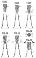
- the legs 13 have a longer length than in FIG. 1, which, at constant elasticity of the material forming them, allows a greater spacing of their lower ends 14 which can make it even more difficult attempted filling with cap 2.
- the lower ends 14 of the legs 13 are substantially flush the lower end of the side wall 9 while having, well understood, a spacing such that they cannot enter, in the free state, in orifice 7.
- This variant is particularly advantageous if it is feared that a user does not try to close the container with the cap 2 in using an instrument such as a blade or pliers to tighten the lower ends 14 of the legs 13.
- the lower ends 14 legs 13 are bevelled by being shorter on their radial edge inner than on their outer radial edge. So during a possible attempt to recap the container, if the end of a tab 13 comes into contact contact with the upper edge 5 of the end piece 4, the tab 13 will tend to escape radially outwards and therefore outside orifice 7.
- the plug 2 comprises a single leg 17 but the lower part of which is divided into several branches 18 deviating from each other downwards so that they have lower ends 19 similar to the ends lower 14 of the variants described above.
- the plug 2 comprises legs 13 of very short length, significantly less than the length axial of the plug, and between which is fixed by fitting a tube plunger 26.
- the plunger tube 26 is generally cylindrical in shape with an upper end 26a formed at an angle and arranged in the channel 16 between the legs 13, and a lower end 26b beyond the lower end 9b of the side wall 9.
- the lower end 26b of the tube 26 is disposed not in the passage 6 but in the inner zone 1a of the bottle body 1.
- the stopper 2 When the bottle is in the normal closed position, the stopper 2 being oriented upwards, the lower end 26b of the tube 26 must be locate at a level between the upper surface of the contained liquid in the body of the bottle 1 and the drop or part of liquid which, for capillarity, is likely to park in the passage 6 of the nozzle 4. This allows degassing without leaving the liquid.
- FIG. 7 we see that we come to present the plug 2 above of the bottle 1, the tabs 13 being in the free state. Then, by a downward axial movement, the plug 2 is brought closer to the orifice 7 of end piece 4, see FIG. 8.
- the tool 20 can be in the form of a plurality of fingers, at least one per leg 13 or per branch 18, capable of moving radially each leg 13 or branch 18 inwards. Fingers the tool 20 can be in a shape resembling the diaphragm of a camera so as to tighten the legs 13 which whatever their number.
- a drop 21 of said liquid generally stays near the shoulder 3 due to a phenomenon of capillarity.
- drop 21 forms in practically all cases insofar as the user shakes the container in order to cause the two components to mix.
- the volume of the drop 21 will of course depend on the physico-chemical characteristics of the liquid, such as its viscosity, its surface tension, its hydrophilicity, etc.
- the drop forms in the upper end of the stopper, in direct contact with its upper wall and can occupy a large part of the passage of the mouthpiece.
- the drop 21 is formed under the shoulder 3 and under the legs 13. Thanks to the invention, the drop is kept axially away from orifice 7.
- Channel 16 will, in general, provide the largest share of the area spreading.
- the channel 16 also forms a means for withdrawing gases from distance of the drop which forms, for the most part, in a place radially and / or axially offset from the lower end of the channel 16 formed at the free end of the legs 13.
- the free section by which the gases escape is small enough that none significant amount of liquid does not come out of the outlet during this step. It is thus possible to sample gases without projection of liquid.
- the inner surface of the end piece 5 is, in the embodiment illustrated, slightly frustoconical, orifice 7 having a diameter lower than that of the base of passage 6 near the shoulder.
- the legs 13 are forced to approach each other during said opening movement, which reduces the free cross-section for the liquid in the passage 6.
- the width of the slots 15 is reduces which causes a spin effect with a drop of part of the gout in the body 1.
- the plug 2 is completely separated from the body 1, the ends 14 of the legs 13 crossing the orifice 7.
- the legs 13 then resume their free form by occupying dimensions transverse greater than those of orifice 7, which prevents the reuse of the plug 2 on the body 1, see FIG. 17.
- the opening of the container occurs without projection of the liquid contained in the container, insofar as a possible drop of liquid is discarded areas through which overpressure gases can escape.
- the legs 13 make it possible to fetch the gases by overpressure beyond drop 21 and allow their escape after rupture of the seal and before complete separation of the plug 2 and of body 1, hence an extremely safe and clean opening of the container.
- exhaust gas causes a small drop of liquid, it spreads over surfaces provided for this purpose and which prevent projection.
- the legs 13 have been replaced by a single protrusion 22 which occupies substantially all the space formed in the end piece 4, and comes flush with the lower surface 24 of the shoulder 25 which here must be of dimension relatively large in the radial direction relative to the axis of the plug.
- This surface of the shoulder and the surface of the lower end 23 of the protuberance 22 provides an almost smooth surface on which none drop of liquid does not form. In general, only a film of liquid of very thin will remain on this surface after mixing the constituents of dye and shaking by the user.
- the rising to the top of the protuberance 22 causes only a very small amount of liquid from the film that formed, this amount tending to spread during movement along the inner wall of the passage 6, which further reduces the quantity likely to be projected during depressurization.
- the seal between the plug 2 and the body 1 can be formed either, as in the other embodiments, near the top wall of the cap or on the contrary near from the lower end 23 of the protuberance 22.
- the invention there is a stopper and a container of economical and safe and clean to use.
- the cap can be fixed by fitting or screwing.
- the risk of projection of liquid in the container is removed when used normal.
- at least part of the passage 6, a liquid tight structure to prevent its stay in said part and permeable to gas to depressurize the container.
- the combination of liquid tightness and gas permeability provides great advantages.
- the plug may, in addition, be provided with means preventing or at the very least very annoying its reuse on the container, which guarantees a single use of the product contained in the container by prompting the user to throw away said container after first use. Finally, no additional parts are added, either to the cap or to the container, both of which can be formed in one piece by molding.
Landscapes
- Engineering & Computer Science (AREA)
- Mechanical Engineering (AREA)
- Closures For Containers (AREA)
- Details Of Rigid Or Semi-Rigid Containers (AREA)
- Containers And Packaging Bodies Having A Special Means To Remove Contents (AREA)
Applications Claiming Priority (4)
| Application Number | Priority Date | Filing Date | Title |
|---|---|---|---|
| FR9909279A FR2796369B1 (fr) | 1999-07-16 | 1999-07-16 | Recipient a ouverture propre et bouchon correspondant |
| FR9909278 | 1999-07-16 | ||
| FR9909278 | 1999-07-16 | ||
| FR9909279 | 1999-07-16 |
Publications (1)
| Publication Number | Publication Date |
|---|---|
| EP1069051A1 true EP1069051A1 (de) | 2001-01-17 |
Family
ID=26235044
Family Applications (1)
| Application Number | Title | Priority Date | Filing Date |
|---|---|---|---|
| EP00402001A Withdrawn EP1069051A1 (de) | 1999-07-16 | 2000-07-12 | Spritzfrei zu öffnender Behälter, sowie entsprechende Kappe |
Country Status (7)
| Country | Link |
|---|---|
| EP (1) | EP1069051A1 (de) |
| JP (1) | JP2003505299A (de) |
| CN (1) | CN1232427C (de) |
| BR (1) | BR0006937A (de) |
| CA (1) | CA2344199A1 (de) |
| MX (1) | MXPA01002372A (de) |
| WO (1) | WO2001005673A1 (de) |
Families Citing this family (4)
| Publication number | Priority date | Publication date | Assignee | Title |
|---|---|---|---|---|
| DE20216175U1 (de) * | 2002-10-21 | 2004-04-08 | Georg Menshen Gmbh & Co. Kg | Behälterverschlusskombination |
| EP2386283A1 (de) * | 2010-05-10 | 2011-11-16 | B. Braun Melsungen AG | Befüllen |
| EP3431407A1 (de) * | 2017-07-21 | 2019-01-23 | Smixin SA | Tülle mit endbereich |
| EP3877285A4 (de) * | 2018-11-07 | 2022-07-13 | L'oreal | Vorrichtung zum verpacken und ausgeben eines produkts mit einem integrierten auffangelement |
Citations (6)
| Publication number | Priority date | Publication date | Assignee | Title |
|---|---|---|---|---|
| US2820564A (en) * | 1956-06-11 | 1958-01-21 | Coty Inc | Bottle neck stoppers |
| FR1273666A (fr) * | 1960-11-15 | 1961-10-13 | Bouchages plastiques | |
| US3944104A (en) * | 1974-11-25 | 1976-03-16 | Consumers Glass Company Limited | Threaded wine bottle stopper |
| FR2607786A1 (fr) * | 1986-12-04 | 1988-06-10 | Mennesson Dominique | Systeme de bouchage de flacons permettant la decharge des gaz contenus dans ces derniers |
| EP0528707A1 (de) | 1991-08-16 | 1993-02-24 | L'oreal | Zwei-Flaschen-Verpackung zur getrennten Aufbewahrung von zwei Produkten, insbesondere flüssigen und zur Mischung derselben vor dem Gebrauch |
| US5785196A (en) * | 1995-05-31 | 1998-07-28 | Rexam Closures Inc. | Closure for a pressurized container |
-
2000
- 2000-07-12 BR BR0006937-0A patent/BR0006937A/pt not_active Application Discontinuation
- 2000-07-12 JP JP2001511341A patent/JP2003505299A/ja not_active Withdrawn
- 2000-07-12 WO PCT/FR2000/002007 patent/WO2001005673A1/fr not_active Ceased
- 2000-07-12 MX MXPA01002372A patent/MXPA01002372A/es unknown
- 2000-07-12 EP EP00402001A patent/EP1069051A1/de not_active Withdrawn
- 2000-07-12 CN CN 00801317 patent/CN1232427C/zh not_active Expired - Fee Related
- 2000-07-12 CA CA002344199A patent/CA2344199A1/fr not_active Abandoned
Patent Citations (6)
| Publication number | Priority date | Publication date | Assignee | Title |
|---|---|---|---|---|
| US2820564A (en) * | 1956-06-11 | 1958-01-21 | Coty Inc | Bottle neck stoppers |
| FR1273666A (fr) * | 1960-11-15 | 1961-10-13 | Bouchages plastiques | |
| US3944104A (en) * | 1974-11-25 | 1976-03-16 | Consumers Glass Company Limited | Threaded wine bottle stopper |
| FR2607786A1 (fr) * | 1986-12-04 | 1988-06-10 | Mennesson Dominique | Systeme de bouchage de flacons permettant la decharge des gaz contenus dans ces derniers |
| EP0528707A1 (de) | 1991-08-16 | 1993-02-24 | L'oreal | Zwei-Flaschen-Verpackung zur getrennten Aufbewahrung von zwei Produkten, insbesondere flüssigen und zur Mischung derselben vor dem Gebrauch |
| US5785196A (en) * | 1995-05-31 | 1998-07-28 | Rexam Closures Inc. | Closure for a pressurized container |
Also Published As
| Publication number | Publication date |
|---|---|
| CA2344199A1 (fr) | 2001-01-25 |
| WO2001005673A1 (fr) | 2001-01-25 |
| JP2003505299A (ja) | 2003-02-12 |
| MXPA01002372A (es) | 2002-05-08 |
| CN1232427C (zh) | 2005-12-21 |
| BR0006937A (pt) | 2001-06-26 |
| CN1315914A (zh) | 2001-10-03 |
Similar Documents
| Publication | Publication Date | Title |
|---|---|---|
| CA2141967C (fr) | Distributeur a plusieurs compartiments pour le stockage et le melange du contenu | |
| CA2057889C (fr) | Verseur pour des flacons et recipients analogues, avec un element perceur pour percer un opercule du goulot des recipients | |
| EP0293290A1 (de) | Verschlussvorrichtung für Behälter | |
| EP1044893A1 (de) | Vorrichtung zum unmittelbaren Vermischen von mindestens zwei Produkten, von denen eines ein Pulver ist | |
| EP1186544A1 (de) | Vorrichtung zur getrennten Aufbewahrung und unmittelbaren Ausgabe von zwei Produkten | |
| FR2806271A1 (fr) | Dispositif pour le melange extemporane d'au moins deux produits | |
| FR2539395A1 (fr) | Recipient permettant de distribuer goutte a goutte une dose de substance fluide | |
| EP0238371A1 (de) | Behälter mit einer viskosen Flüssigkeit, die beim ersten Verbrauch mit einem Zusatz versehen werden kann | |
| EP1033323A1 (de) | Behälter zur Mischung von verschiedenen Komponenten zur Bildung eines Produktes | |
| EP1751023B1 (de) | Verteilvorrichtung für parfum | |
| EP1221419B1 (de) | Vorrichtung zum unmittelbaren Vermischen von zwei Produkten | |
| WO2008078031A2 (fr) | Flacon destine a recevoir une dose determinee d'un liquide | |
| EP0905049B1 (de) | Behälter für ein Dreikomponenten-Produkt | |
| EP0611356B1 (de) | Verpackungstube für paste, versehen mit einer durch einen schraubenverschluss verschlossenen nachfüllöffnung | |
| EP1069051A1 (de) | Spritzfrei zu öffnender Behälter, sowie entsprechende Kappe | |
| FR2665647A1 (fr) | Flacon pour reactifs chimiques. | |
| WO2008152219A1 (fr) | Bouchon pour recipient formant reservoir d'additif | |
| FR2796369A1 (fr) | Recipient a ouverture propre et bouchon correspondant | |
| EP0082778B1 (de) | Kanister und Behältereinheit bestehend aus einem Kanister und einem Flakon | |
| EP0083273B1 (de) | Zerstörbarer Einwegverschluss und Behälter mit diesem Verschluss versehen | |
| EP2146923B1 (de) | Verschlussdeckel für einen behälter zur aufbewahrung von kohlensäurehaltigen flüssigkeiten und behälter mit derartigem verschluss | |
| EP3489167B1 (de) | Anordnung, die eine verschlusskappe und einen behälter umfasst | |
| FR2654076A1 (fr) | Recipient a au moins deux compartiments isoles et procede de remplissage d'un tel recipient. | |
| FR2615828A1 (fr) | Dispositif de fermeture pour recipients | |
| FR2701249A1 (fr) | Dispositif de fermeture de l'extrémité d'un tube à paroi souple. |
Legal Events
| Date | Code | Title | Description |
|---|---|---|---|
| PUAI | Public reference made under article 153(3) epc to a published international application that has entered the european phase |
Free format text: ORIGINAL CODE: 0009012 |
|
| 17P | Request for examination filed |
Effective date: 20000724 |
|
| AK | Designated contracting states |
Kind code of ref document: A1 Designated state(s): AT BE CH CY DE DK ES FI FR GB GR IE IT LI LU MC NL PT SE |
|
| AX | Request for extension of the european patent |
Free format text: AL;LT;LV;MK;RO;SI |
|
| AKX | Designation fees paid |
Free format text: AT BE CH CY DE DK ES FI FR GB GR IE IT LI LU MC NL PT SE |
|
| 17Q | First examination report despatched |
Effective date: 20021203 |
|
| GRAP | Despatch of communication of intention to grant a patent |
Free format text: ORIGINAL CODE: EPIDOSNIGR1 |
|
| STAA | Information on the status of an ep patent application or granted ep patent |
Free format text: STATUS: THE APPLICATION IS DEEMED TO BE WITHDRAWN |
|
| 18D | Application deemed to be withdrawn |
Effective date: 20060718 |