EP1069002B1 - Hinten angebrachte Rückhaltebügel für Bedienungsperson - Google Patents
Hinten angebrachte Rückhaltebügel für Bedienungsperson Download PDFInfo
- Publication number
- EP1069002B1 EP1069002B1 EP20000114902 EP00114902A EP1069002B1 EP 1069002 B1 EP1069002 B1 EP 1069002B1 EP 20000114902 EP20000114902 EP 20000114902 EP 00114902 A EP00114902 A EP 00114902A EP 1069002 B1 EP1069002 B1 EP 1069002B1
- Authority
- EP
- European Patent Office
- Prior art keywords
- restraint bar
- bar
- restraint
- mounting
- pivot
- Prior art date
- Legal status (The legal status is an assumption and is not a legal conclusion. Google has not performed a legal analysis and makes no representation as to the accuracy of the status listed.)
- Expired - Lifetime
Links
Images


Classifications
-
- B—PERFORMING OPERATIONS; TRANSPORTING
- B60—VEHICLES IN GENERAL
- B60R—VEHICLES, VEHICLE FITTINGS, OR VEHICLE PARTS, NOT OTHERWISE PROVIDED FOR
- B60R21/00—Arrangements or fittings on vehicles for protecting or preventing injuries to occupants or pedestrians in case of accidents or other traffic risks
- B60R21/02—Occupant safety arrangements or fittings, e.g. crash pads
-
- B—PERFORMING OPERATIONS; TRANSPORTING
- B60—VEHICLES IN GENERAL
- B60R—VEHICLES, VEHICLE FITTINGS, OR VEHICLE PARTS, NOT OTHERWISE PROVIDED FOR
- B60R21/00—Arrangements or fittings on vehicles for protecting or preventing injuries to occupants or pedestrians in case of accidents or other traffic risks
- B60R2021/0065—Type of vehicles
- B60R2021/0074—Utility vehicles
- B60R2021/0081—Working vehicles
-
- B—PERFORMING OPERATIONS; TRANSPORTING
- B60—VEHICLES IN GENERAL
- B60R—VEHICLES, VEHICLE FITTINGS, OR VEHICLE PARTS, NOT OTHERWISE PROVIDED FOR
- B60R21/00—Arrangements or fittings on vehicles for protecting or preventing injuries to occupants or pedestrians in case of accidents or other traffic risks
- B60R21/02—Occupant safety arrangements or fittings, e.g. crash pads
- B60R2021/0206—Self-supporting restraint systems, e.g. restraining arms, plates or the like
Definitions
- the present invention relates to loader operator restraint bars for mounting in skid steer loader cabs, wherein the bar is mounted on the rear wall and the front cross member moves upwardly to a non-restraint position and then downwardly to a position where it extends across the lap of an operator sitting on the seat.
- the restraint bar position can be sensed for use with an operating interlock for the loader such that when the restraint bar is raised, operation of at least some function of the loader is prevented.
- US-A-4397371 illustrates an operator restraint system which has a restraint member that is mounted at the forward side of an operator's cab, and is tied into a control system of the loader.
- Rear mounted restraint systems also have been utilized, for example, those shown in US-A-5050700 and US-A-5383532
- GB-A-2 328 268 discloses a pedal locking device for a loader vehicle, comprising a vehicle body with a cab and a seat and hydraulically operated working implements, eg boom, bucket and attachment, which are controlled via a hydraulic control valve unit operated by respective pedals.
- a seat bar swings between a lowered position in which an operator is secured to the seat and a raised position in which the operator is released from the seat.
- the pedals can be locked in the neutral position by detent levers which engage dog plates attached to the pedals and are spring-biassed into the locking position.
- a Bowden cable interconnects the seat bar and the detent levers so that as the seat bar is lowered the pedals are unlocked and as the seat bar is raised the pedals are locked again.
- the existing rear mounted restraint bars are relatively complex in mounting, and a simplified, easily installed and easily operated restraint for an operator is desired.
- the operator restraint forms a complete subassembly that can be made separate from the loader cab.
- the present invention relates to a rear mounted operator restraint bar or seat bar, that mounts on the rear wall of an operator cab of a skid steer loader, where the mounting is out of the way and leaves the front cab area unobstructed.
- the restraint bar is a U-shaped member that has a pair of mounting brackets for side legs on the rear wall, each with a self-contained spring. The bracket springs will urge the bar to a restraint position after it has been lowered near such position, and when lifted by the operator, will hold the bar is a release position so that the operator can move in and out of the cab.
- one bracket of the restraint bar mounting can mount a sensor that will provide a signal indicating that the restraint bar is in a selected position, and couple the signal into a control system so that the loader drive and operating systems are disabled unless the restraint bar is down.
- a rear mounted operator restraint bar for a vehicle cab has a pair of side arms, with each of said side arms being mounted on a separate mounting bracket.
- a pivot connection is provided between the side arms and the respective separate mounting bracket.
- the mounting brackets have a mounting wall that is supported on the rear wall of the cab and a spring bracket is attached to at least one arm.
- a compression coil spring has a first end bearing against a portion of the spring bracket for applying a force at a first location and has an opposite end pivotally mounted on the associated mounting bracket at a pivot off-set from the pivot of an associated restraint bar arm. The pivot of the spring on the associated mounting bracket, the first location and the pivot connection of the associated arm pass over center when the restraint bar is moved from a working position to a raised position so the restraint bar then remains in its raised position.
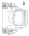
- a cab 10 of a skid steer loader is of conventional design, and the skid steer loader on which it goes is also of conventional design.
- the cab as shown, has the windows removed, but has the front end 12, and a rear wall 14.
- An operator's seat 16 is made for an operator, who will sit and operate controls of conventional design.
- the bar 20 is a generally U-shaped bar that has a forward cross member 21 that extends laterally across the lap of an operator sitting on the seat 16, and fore and aft extending side arms 23.
- the side arms 23 are bent and have generally uprightly inclined portions 24 that are mounted onto separate mounting bracket assemblies 26 and 28, respectively.
- bracket assemblies 26 and 28 are essentially the same, except being adapted for the right and left sides and the mounting bases can be interchanged.
- the mounting for the restraint bar itself is slightly different for the right and left sides.
- Each of the bracket assemblies has a generally U-shaped channel base 30 that is formed as a unitary channel having spaced apart legs 32 and 34, that extend forwardly from a base wall 36.
- a downwardly extending support tongue or wall 38 is integral with the base wall 36 (see Figure 7, for example) and is formed to provide a planar offset stop wall portion 40, and a leg 42 that is bent back toward the cab rear wall 14 and rests against the wall 14 when the bracket assemblies 26 and 28 are fastened in place with suitable bolts or cap screws indicated at 44, in Figures 1 and 2, for example.
- the laterally extending restraint bar cross member 21, the restraint bar side arms 23, and the lower parts 24 of the vertical or upright sections of the restraint bar are tubular, and are selected to be capable of absorbing energy from loads exerted when the operator tends to be moved under inertial forces.
- the operator also will use a conventional lap belt, which is not shown.
- the arm portions 24 are joined to flat bar pivot arms 48 that are used for pivotally mounting the restraint bar to the respective bracket assemblies 26 and 28 on pivot pins 49 that extend between the individual legs 32 and 34 of each of the bases 30.
- This can be seen in Figures 4 and 5, which show the difference in mounting for the right and left-hand bracket assemblies 26 and 28.
- the pivot arm 48 is broken away to show that the pivot arms 48 have a large pivot opening that fits onto a bushing 50 that has a thrust flange 52 that rides against the leg 32 of the bracket assembly 28 on that side of the cab.
- a spacer 54 is used in connection with another bushing 56 to hold that pivot arm 48 against the leg 32 of the base 30. The spacers will positively position the pivoting section 48 of the restraint bar.
- a bushing 50 is also used on the pivot arm 48 shown in Figure 5, but the pivot arm on that side of the cab is held adjacent leg 34 of base bracket 30. Both pivot arms 48 are held adjacent the inside leg of their respective bases 30.
- a spring assembly 60 is mounted on each of the bracket assemblies.
- the spring assemblies include compression springs 60 having first ends supported on inwardly bent legs 62A and 64A on shield brackets 62 and 64 on the respective sides of the restraint bar.
- the compression springs 66 are mounted over sliding rods 68 using suitable bushings 70 at the opposite ends of the springs.
- the bushings 70 at the first ends of the springs 66 are supported on legs 62A and 64A.
- Each rod 68 has a clevis 72 at the respective second end, and each clevis is pinned with a pin 74 to one of the legs of the bases 30 of bracket assemblies 26 and 28.
- the clevis 72 for the spring 66 on that side of the restraint bar is mounted on the bracket leg 34, and as shown in Figure 5, the clevis 72 for the bracket assembly 26 is mounted on the leg 32 of that bracket 30.
- the upper bushing 70 of each adjacent the clevis 72 is anchored to the rod 68 so the spring force acts against respective leg 62A or 64A.
- the springs 66 are of length so that they will exert a force against the legs 62A or 64A tending to pivot the restraint base about the pivot pins 49.
- the shield brackets 62 and 64 are welded onto the respective pivot arm 48, and the position of the pin 74 for the clevis, the openings through which the rods 68 pass on the legs 62A and 64A, and the position of pivot pins 49 for the pivot arms 48 will determine how the loading from the springs will effect the pivoting of the operator restraint bar.
- the brackets 62 and 64 have stop flanges 79 bent down from the legs 62A and 64A and extending generally parallel to walls 40 of the bases 30 with the restraint bar in its lowered position.
- the springs 66 are selected so that the downward force to pull the restraint bar down from its raised position shown in Figure 1 is less than that needed to lift the bar, and it would be about 15 pounds.
- the brackets 62A and 64A have forward walls 62B and 64B that shield the springs 66 substantially, as shown in Figures 4 and 5, and protects them from damage, as well as shielding them from exterior members.
- clevis pins 74 are supported on shouldered bushings 84 that have a flange that rides against the respective legs 32 or 34 of the bracket 30, and have a large diameter outer sleeve section that passes through a large opening in the respective bracket leg 32 or 34 to provide a greater surface area for pivoting and to support the springs on the relatively narrow legs 32 and 34 of the bases 30.
- the bushings 84 provide a larger surface area for operation, and are similar to the use of the bushing 50 for the pivoting arms 48.
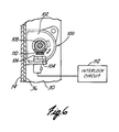
- the bracket assembly 26 includes components for sensing the position of the operator restraint bar when it is in its lowered position, to provide an interlock signal that will enable operation of the loader only when the restraint bar is down. If the restraint bar is not in its lowered position, the loader cannot be operated.
- a Hall Effect sensor assembly 100 is mounted onto the leg or wall 32 of the base 30 forming part of the bracket assembly 26, and includes a part annular support frame 102 spaced from a rotating bushing 108 that rotates with the restraint bar about pivot pin 49.
- the frame 102 supports a circuit board 104 at a lower side, and the circuit board 104 has a Hall Effect sensor 106 that is positioned adjacent to the rotating bushing 108.
- the bushing 108 also serves as a spacer to bear on flange 52 for the bushing 50 on bracket assembly 26.
- the pivoting arm 48 on bracket assembly 26 is thus held adjacent leg 34 of that base 30.
- the bushing 108 is keyed so it will turn with the pivot arm 48 on that side of the restraint bar.
- the bushing mounts a pair of magnets 110 that will move arcuately as the restraint bar pivots to its raised position, so the magnets 110 become spaced a greater distance from the Hall Effect sensor 106 than when the bar is in its lowered position as shown in Figure 6.
- the magnets 110 When the restraint bar 20 is in the lowered position, the magnets 110 will affect the Hall Effect sensor 106 in a known manner and a signal will be provided to an interlock circuit 112. The signal that the restraint bar is in its lowered position will arm the interlock circuit with a signal indicating that at least one of the conditions for operation of the loader has been met. If there are other inputs to the interlock circuit, such as a sensor to sense that an operator is seated in the seat 16, those signals also have to be in the proper state for operation of the loader.
- the magnets 110 are spaced from the Hall Effect sensor 106 and the lack of a signal to the interlock circuit 112 will lock up the loader operational functions so that the loader cannot be moved, and the boom or bucket or whatever other implement is on the loader cannot be operated until the restraint bar is moved to its working, lowered position.
- Additional inputs to the interlock circuit can also be an operator energized switch that would have to be pushed after the operator was sitting in the seat, or similar interlock functions.
- the individual bracket assemblies 26 and 28 can be preassembled onto the operator restraint pivot bars 48, and thus the operator restraint forms a complete sub-assembly that can be made separate from the loader cab and other portions of the loader, as shown in Figure 6, and then merely bolted in place on the loader as a unit.
- Figure 8 shows the finished sub assembly wherein the restraint bar 20 is covered with a suitable foam padding indicated at 120.
- the foam padding also will cover the shields or flanges 64B and 62B of the spring brackets 62 and 64.
- bracket assemblies are easily made, and provide positive positioning of the restraint bar in raised and lowered positions, as well as ensuring that the installation is done with a minimum of time by having the ability to pre-assemble the brackets and the seat bar.
Landscapes
- Engineering & Computer Science (AREA)
- Mechanical Engineering (AREA)
- Component Parts Of Construction Machinery (AREA)
- Body Structure For Vehicles (AREA)
- Forklifts And Lifting Vehicles (AREA)
Claims (8)
- Hinten angebrachter Rückhaltebügel (20) für eine Bedienungsperson in einer Fahrzeugkabine (10) mit einer Rückwand (14), wobei der Rückhaltebügel (20) U-förmig ist und aufweist: ein Paar von Seitenarmen (23), wobei jeder Seitenarm (23) eingerichtet ist, um relativ zu einer Kabine (10) drehbar angebracht zu werden, ein Drehgelenk (49), um die Arme (23) relativ zur Kabine (10) drehbar anzubringen, eine Feder (66), die zwischen der Kabine (10) und dem Rückhaltebügel (20) so an Drehpunkten (74,62A,64B) drehbar angebracht ist, daß ein Federdrehpunkt (62A,62B) durch das Zentrum hindurchgeht, wenn der Rückhaltebügel (20) von einer Arbeitsposition in eine angehobene Position bewegt wird, um eine Kraft bereitzustellen, die den Rückhaltebügel (20) zwingt, in der Arbeitsposition zu bleiben bzw. auch in der angehobenen Position zu bleiben, nachdem der Rückhaltebügel (20) ein gewähltes Maß angehoben worden ist,
gekennzeichnet durch
Befestigungsklammern (26,28) und eine Befestigungswand (36) und dadurch, daß der Rückhaltebügel (20) drehbar an einer jeweiligen Befestigungsklammer (26,28) angebracht ist und die Feder (66) an einem Ende an einem ersten Federdrehpunkt (74) an einer der Befestigungsklammern (26,28) und an einem gegenüberliegenden Ende (62A,62B) an dem Rückhaltebügel (20) angebracht ist. - Hinten angebrachter Rückhaltebügel für eine Bedienungsperson nach Anspruch 1, ferner dadurch gekennzeichnet, daß die Feder (66) eine Druckschraubenfeder (66) aufweist und die Drehverbindung (62A,62B) mit dem Rückhaltebügel (20) die Druckschraubenfeder (66) lagert.
- Hinten angebrachter Rückhaltebügel nach einem der Ansprüche 1 oder 2, ferner dadurch gekennzeichnet, daß jede der Befestigungsklammern (26,28) kanalförmige Klammern aufweist, die Seitenbeine (32,34) haben, und dadurch, daß die Befestigungswand (36) jeder Klammer (26,28) eine Basiswand (36) aufweist, die an der Rückwand (14) der Laderkabine (10) anliegt, wobei jede der Befestigungsklammern (26,28) ein erstes Seitenbein (32,34), das zu einer angrenzenden Seite der Laderkabine (10) hin angeordnet ist, und ein zweites Seitenbein (32,34) hat, das einwärts in einem Abstand zum ersten Bein (32,34) angeordnet ist, und dadurch, daß die Arme (23) des Rückhaltebügels (20) drehbar an dem zweiten Bein (32,34) der jeweiligen Befestigungsklammer (26,28) angebracht sind.
- Hinten angebrachter Rückhaltebügel nach Anspruch 3, ferner dadurch gekennzeichnet, daß die Drehverbindung (74) zwischen der Feder (66) und der zugehörigen Befestigungsklammer (26,28) eine Verbindung zu dem ersten Bein (32,34) der zugehörigen Befestigungsklammer (26,28) ist.
- Hinten angebrachter Rückhaltebügel nach einem der vorstehenden Ansprüche, ferner dadurch gekennzeichnet, daß mindestens einer der Rückhaltebügelarme (23) einen Sensor (100) hat, um eine Position des Rückhaltebügels (20) zu erfassen.
- Hinten angebrachter Rückhaltebügel nach einem der Ansprüche 1 bis 5, ferner dadurch gekennzeichnet, daß sich die Befestigungswände (36) der Befestigungsklammern (26,28) in eine Richtung entlang Abschnitte der Arme (23) des Rückhaltebügels (20) erstrecken, und dadurch, daß Anschlagelemente (40) an der Befestigungswand (36) geformt sind, um mit den Armen (23) des Rückhaltebügels (20) in Eingriff zu sein, wenn der Rückhaltebügel (20) in einer Arbeitsposition ist.
- Hinten angebrachter Rückhaltebügel nach Anspruch 5 oder 6, ferner dadurch gekennzeichnet, daß der Sensor (100) einen Halleffektsensor aufweist, der einen ersten Abschnitt (106) und einen zweiten Abschnitt (110) umfaßt, wobei der erste Abschnitt (106) an einer Sensorklammer (102) neben dem Drehpunkt (49) des mindestens einen Arms (23) des Bedienungsperson-Rückhaltebügels angebracht ist und wobei der andere Abschnitt (110) des Halleffektsensors angebracht ist, um sich um den Drehpunkt (49) des mindestens einen Arms des Rückhaltebügels (23) zu bewegen, wenn der Rückhaltebügel (20) gedreht wird.
- Hinten angebrachter Rückhaltebügel nach einem der Ansprüche 1 bis 7, ferner dadurch gekennzeichnet, daß eine Rückhaltebügel-Baugruppe die Befestigungsklammern (26,28), Federn (66), Anschlagelemente (40) und den Rückhaltebügel (20) aufweist, wobei die Baugruppe geeignet ist, direkt an der Rückwand (14) der Kabine (10) angeordnet zu werden.
Applications Claiming Priority (2)
| Application Number | Priority Date | Filing Date | Title |
|---|---|---|---|
| US09/352,082 US6299207B1 (en) | 1999-07-14 | 1999-07-14 | Rear mounted operator restraint bar |
| US352082 | 1999-07-14 |
Publications (2)
| Publication Number | Publication Date |
|---|---|
| EP1069002A1 EP1069002A1 (de) | 2001-01-17 |
| EP1069002B1 true EP1069002B1 (de) | 2004-10-27 |
Family
ID=23383722
Family Applications (1)
| Application Number | Title | Priority Date | Filing Date |
|---|---|---|---|
| EP20000114902 Expired - Lifetime EP1069002B1 (de) | 1999-07-14 | 2000-07-14 | Hinten angebrachte Rückhaltebügel für Bedienungsperson |
Country Status (8)
| Country | Link |
|---|---|
| US (1) | US6299207B1 (de) |
| EP (1) | EP1069002B1 (de) |
| JP (1) | JP2001090117A (de) |
| KR (1) | KR20010049791A (de) |
| AU (1) | AU4515200A (de) |
| CA (1) | CA2313585C (de) |
| DE (1) | DE60015241T2 (de) |
| ES (1) | ES2224974T3 (de) |
Families Citing this family (36)
| Publication number | Priority date | Publication date | Assignee | Title |
|---|---|---|---|---|
| DE10009549B4 (de) * | 2000-02-29 | 2006-04-13 | Linde Ag | Rückhaltesystem |
| EP1145919B1 (de) * | 2000-04-14 | 2005-06-29 | Hans Sauermann | Rückhaltesystem für einen Fahrer, insbesondere eines Flurförderfahrzeugs |
| US6494145B2 (en) * | 2000-09-15 | 2002-12-17 | Joseph F. Kernan | Automatic crossbar on ski chair-lift for facilitating passenger dismount |
| US6513817B2 (en) * | 2001-02-23 | 2003-02-04 | Mccue Corporation | Shopping cart having a child supporting apparatus |
| USD485395S1 (en) | 2001-03-14 | 2004-01-13 | Kevin Mobley | Police vehicle prisoner restraint |
| DE20120897U1 (de) * | 2001-12-28 | 2003-05-08 | IWS Ingenieurgesellschaft Weiner & Schröter mbH,, 47475 Kamp-Lintfort | Schutztür für Fahrerkabinen, insbesondere von Nutzfahrzeugen |
| US6732829B2 (en) | 2002-01-04 | 2004-05-11 | Clark Equipment Company | Load absorbing operator restraint bar |
| US6971316B2 (en) * | 2002-09-16 | 2005-12-06 | Hansen Ned R | Restraint |
| US6902024B2 (en) * | 2002-11-27 | 2005-06-07 | Clark Equipment Company | Lateral operator restraint system and position sensor for material handler |
| US7159684B2 (en) * | 2002-11-27 | 2007-01-09 | Clark Equipment Company | Interlock control system on wheeled work machine |
| US7235901B2 (en) * | 2003-07-11 | 2007-06-26 | Clark Equipment Company | Sensor and interlock on an industrial vehicle |
| US7556291B2 (en) * | 2005-01-26 | 2009-07-07 | Indiana Mills & Manufacturing Inc. | Vehicle restraint system |
| US7757806B2 (en) * | 2005-12-22 | 2010-07-20 | Caterpillar Sarl | Adjustable operator interface |
| US7740259B2 (en) * | 2006-02-03 | 2010-06-22 | Crown Equipment Corporation | Movable step for a materials handling vehicle |
| US20070228712A1 (en) * | 2006-04-04 | 2007-10-04 | Hansen Robert T | Vehicle restraint systems and methods of restraining vehicle occupants |
| AT504614B1 (de) * | 2006-12-04 | 2009-02-15 | Innova Patent Gmbh | Schliessbügel eines sessels eines sesselliftes |
| USD573162S1 (en) * | 2007-04-24 | 2008-07-15 | Kabushiki Kaisha Toyota Jidoshokki | Seat bar for working vehicles |
| US7699128B1 (en) * | 2007-05-03 | 2010-04-20 | Strauss Lydia J | Electric vehicle |
| USD583837S1 (en) * | 2008-02-29 | 2008-12-30 | Komatsu Ltd. | Seat bar for skid-steer loader |
| USD586827S1 (en) * | 2008-02-29 | 2009-02-17 | Komatsu Ltd. | Seat bar for skid-steer loader |
| EP2349814B1 (de) * | 2008-10-14 | 2013-12-04 | Crown Equipment Corporation | Halteeinrichtung für palettenwagen |
| US8226155B2 (en) * | 2009-01-27 | 2012-07-24 | Clark Equipment Company | Work machine vehicle having joystick controls on an adjustable suspended seatbar |
| US7971677B2 (en) * | 2009-01-27 | 2011-07-05 | Clark Equipment Company | Work machine vehicle having seat mounted controls with nested seatbar |
| US8132514B2 (en) * | 2009-06-05 | 2012-03-13 | Disney Enterprises, Inc. | Lap bar assembly with locking mechanism with locking in lap bar and grab bar positions |
| US11198408B2 (en) * | 2009-11-12 | 2021-12-14 | Excel Industries, Inc. | Control system for a terrain working vehicle having an operator protection apparatus |
| US10377333B2 (en) | 2009-11-12 | 2019-08-13 | Excel Industries, Inc. | Deployable operator protection apparatus with an over-center linkage |
| US11724658B2 (en) | 2009-11-12 | 2023-08-15 | Excel Industries, Inc. | Control system for a terrain working vehicle having an operator protection apparatus |
| WO2011103351A2 (en) * | 2010-02-18 | 2011-08-25 | Inteva Products Llc. | Restraint system for vehicle |
| US8967717B2 (en) | 2011-12-13 | 2015-03-03 | Robert Miller Sims | Portable child restraining seat |
| CN102897203B (zh) * | 2012-09-26 | 2017-11-17 | 苏州先锋物流装备科技有限公司 | 一种可复位的转向机构 |
| EP3003789B1 (de) | 2013-06-04 | 2018-08-01 | Antonio Zamperla S.p.A. | Insassenrückhaltevorrichtung für fahrgeschäfte |
| US9340180B2 (en) * | 2013-09-16 | 2016-05-17 | Matthew J. Planer | Supplemental restraint system for police vehicles |
| JP6261274B2 (ja) * | 2013-10-09 | 2018-01-17 | 株式会社ユー・エス・ジェイ | 遊戯用乗物の安全支援装置 |
| US9330305B2 (en) | 2013-12-29 | 2016-05-03 | Google Technology Holdings LLC | Method and device for detecting a seating position in a vehicle |
| JP6609579B2 (ja) * | 2017-01-31 | 2019-11-20 | 合同会社ユー・エス・ジェイ | 乗客安全乗物 |
| DE202017005064U1 (de) * | 2017-09-28 | 2019-01-02 | HSM Hans Sauermann GmbH & Co. KG | Rückhaltesystem für einen Fahrer eines Fahrzeugs |
Family Cites Families (27)
| Publication number | Priority date | Publication date | Assignee | Title |
|---|---|---|---|---|
| US1597491A (en) * | 1925-10-21 | 1926-08-24 | Harry G Traver | Car for amusement rides |
| US2755101A (en) | 1955-08-05 | 1956-07-17 | Charles H Budde | Safety passenger-holding device |
| US3453026A (en) * | 1967-08-28 | 1969-07-01 | Artnell Co | Vehicle seat safety bar |
| US3494633A (en) * | 1968-01-17 | 1970-02-10 | Paul V Malloy | Passenger safety device for vehicle |
| US3640572A (en) * | 1969-12-16 | 1972-02-08 | Emil J Doehler | Vehicle safety guard |
| US3888329A (en) * | 1971-07-16 | 1975-06-10 | James Monaghan | Vehicle safety device |
| US3899042A (en) * | 1974-04-29 | 1975-08-12 | George D Bonar | Automobile seat automatic passenger-securing device |
| US3993157A (en) | 1975-08-04 | 1976-11-23 | Deere & Company | Door operated control lever latch mechanism |
| US4008626A (en) | 1975-09-10 | 1977-02-22 | Deere & Company | Linkages for moving and retaining a control lever to and in a non-use position |
| US4392660A (en) | 1980-08-29 | 1983-07-12 | Mason James V | Safety bar |
| US4388980A (en) | 1981-01-26 | 1983-06-21 | Clark Equipment Company | Operator restraint for a loader |
| US4391344A (en) | 1981-01-26 | 1983-07-05 | Clark Equipment Company | Loader operator restraint |
| US4397371A (en) * | 1981-01-26 | 1983-08-09 | Clark Equipment Company | Loader operator restraint system |
| US4480713A (en) | 1982-11-16 | 1984-11-06 | Owatonna Manufacturing Company, Inc. | Operator restraint/control lockout system |
| US4579191A (en) | 1984-11-05 | 1986-04-01 | J. I. Case Company | Operator restraint system |
| US4603877A (en) * | 1985-04-15 | 1986-08-05 | General Motors Corporation | Control means for occupant restraint belt system |
| US4955452A (en) | 1989-04-20 | 1990-09-11 | Trak International, Inc. | Locking apparatus for skid steer loader |
| US5050700A (en) | 1989-06-05 | 1991-09-24 | Daewoo Heavy Industries Ltd. | Safety apparatus for a skid-steer loader |
| US5129478A (en) | 1990-07-31 | 1992-07-14 | Toyo Umpanki Co., Ltd. | Seat occupant restraining device |
| US5100173A (en) | 1990-12-20 | 1992-03-31 | Kudler Jeffrey P | Lap bar for bumper cars |
| JP2560922B2 (ja) | 1991-03-18 | 1996-12-04 | 株式会社豊田自動織機製作所 | 荷役車両における踏み込みペダルのロック装置 |
| US5454596A (en) * | 1993-04-15 | 1995-10-03 | Dirck; Ronald L. | Safety restraint apparatus |
| US5481909A (en) * | 1994-03-07 | 1996-01-09 | Motorola, Inc. | Apparatus and method for measuring reciprocating engine performance dependent on positional behavior of a member driven by engine torque |
| JP2682817B2 (ja) | 1995-07-12 | 1997-11-26 | 新キャタピラー三菱株式会社 | 建設機械の操作遮断装置 |
| US5944135A (en) * | 1996-11-14 | 1999-08-31 | Trw Vehicle Safety Systems Inc. | Seat belt buckle with field effect locking indicator and method of use |
| US5871063A (en) * | 1997-01-22 | 1999-02-16 | Automotive Systems Laboratory, Inc. | Seat belt latch sensor system |
| KR100211449B1 (ko) | 1997-07-28 | 1999-08-02 | 추호석 | 로더용 페달록킹장치 |
-
1999
- 1999-07-14 US US09/352,082 patent/US6299207B1/en not_active Expired - Lifetime
-
2000
- 2000-07-07 CA CA002313585A patent/CA2313585C/en not_active Expired - Lifetime
- 2000-07-10 AU AU45152/00A patent/AU4515200A/en not_active Abandoned
- 2000-07-14 KR KR1020000040548A patent/KR20010049791A/ko not_active Withdrawn
- 2000-07-14 EP EP20000114902 patent/EP1069002B1/de not_active Expired - Lifetime
- 2000-07-14 DE DE60015241T patent/DE60015241T2/de not_active Expired - Lifetime
- 2000-07-14 JP JP2000213585A patent/JP2001090117A/ja active Pending
- 2000-07-14 ES ES00114902T patent/ES2224974T3/es not_active Expired - Lifetime
Also Published As
| Publication number | Publication date |
|---|---|
| US6299207B1 (en) | 2001-10-09 |
| CA2313585C (en) | 2008-09-16 |
| CA2313585A1 (en) | 2001-01-14 |
| JP2001090117A (ja) | 2001-04-03 |
| ES2224974T3 (es) | 2005-03-16 |
| KR20010049791A (ko) | 2001-06-15 |
| AU4515200A (en) | 2001-01-18 |
| EP1069002A1 (de) | 2001-01-17 |
| DE60015241T2 (de) | 2005-03-10 |
| DE60015241D1 (de) | 2004-12-02 |
Similar Documents
| Publication | Publication Date | Title |
|---|---|---|
| EP1069002B1 (de) | Hinten angebrachte Rückhaltebügel für Bedienungsperson | |
| US5364151A (en) | Adjustable seat apparatus for utility vehicle | |
| US4388980A (en) | Operator restraint for a loader | |
| EP1570132B1 (de) | Seitliches rückhaltesystem für fahrer mit lagesensor für fahrzeuge zur handhabung von materialien | |
| US5246271A (en) | Vehicle seats with built-in safety belt | |
| US4685731A (en) | Tank crew seat structure | |
| US8226155B2 (en) | Work machine vehicle having joystick controls on an adjustable suspended seatbar | |
| CA1190197A (en) | Operator restraint/control lockout system | |
| EP0061394A1 (de) | Verstellbare Oberschenkelstütze für Fahrzeugsitz | |
| JPH072006A (ja) | 自動車シートのクツシヨン上昇装置 | |
| GB2277869A (en) | Safety restraining device for the driver of a lift truck | |
| US5879122A (en) | Container moving vehicle | |
| US4005845A (en) | Seat assembly including a turnaround-type seat | |
| WO2005118965A2 (en) | Relocatable position operator seat station for loader | |
| CA2856624C (en) | Front loader arrangement | |
| US5524722A (en) | Skid steer loader seat mechanism | |
| EP1264940B1 (de) | Baggerlader mit spezieller Anordnung der Bedienhebel | |
| EP0713800B1 (de) | Kraftfahrzeugrücksitz | |
| WO1990014064A1 (en) | A device in wheel chairs | |
| EP1186469A1 (de) | Eine Rückenlehne für einen Kraftfahrzeugsitz, insbesondere für einen Rücksitz | |
| JPH0619402Y2 (ja) | 車両用シート | |
| JP2022030874A (ja) | フロントマウント型乗用草刈機 | |
| JPH0242086Y2 (de) | ||
| JP7775504B2 (ja) | レバー装置及びそれを備えた作業機 | |
| JPS6346473Y2 (de) |
Legal Events
| Date | Code | Title | Description |
|---|---|---|---|
| PUAI | Public reference made under article 153(3) epc to a published international application that has entered the european phase |
Free format text: ORIGINAL CODE: 0009012 |
|
| 17P | Request for examination filed |
Effective date: 20000811 |
|
| AK | Designated contracting states |
Kind code of ref document: A1 Designated state(s): BE DE ES FR GB IT |
|
| AX | Request for extension of the european patent |
Free format text: AL;LT;LV;MK;RO;SI |
|
| AKX | Designation fees paid |
Free format text: BE DE ES FR GB IT |
|
| 17Q | First examination report despatched |
Effective date: 20030428 |
|
| GRAP | Despatch of communication of intention to grant a patent |
Free format text: ORIGINAL CODE: EPIDOSNIGR1 |
|
| GRAS | Grant fee paid |
Free format text: ORIGINAL CODE: EPIDOSNIGR3 |
|
| GRAA | (expected) grant |
Free format text: ORIGINAL CODE: 0009210 |
|
| AK | Designated contracting states |
Kind code of ref document: B1 Designated state(s): BE DE ES FR GB IT |
|
| PG25 | Lapsed in a contracting state [announced via postgrant information from national office to epo] |
Ref country code: BE Free format text: LAPSE BECAUSE OF FAILURE TO SUBMIT A TRANSLATION OF THE DESCRIPTION OR TO PAY THE FEE WITHIN THE PRESCRIBED TIME-LIMIT Effective date: 20041027 |
|
| REG | Reference to a national code |
Ref country code: GB Ref legal event code: FG4D |
|
| REF | Corresponds to: |
Ref document number: 60015241 Country of ref document: DE Date of ref document: 20041202 Kind code of ref document: P |
|
| REG | Reference to a national code |
Ref country code: ES Ref legal event code: FG2A Ref document number: 2224974 Country of ref document: ES Kind code of ref document: T3 |
|
| PLBE | No opposition filed within time limit |
Free format text: ORIGINAL CODE: 0009261 |
|
| STAA | Information on the status of an ep patent application or granted ep patent |
Free format text: STATUS: NO OPPOSITION FILED WITHIN TIME LIMIT |
|
| ET | Fr: translation filed | ||
| 26N | No opposition filed |
Effective date: 20050728 |
|
| PGFP | Annual fee paid to national office [announced via postgrant information from national office to epo] |
Ref country code: ES Payment date: 20100726 Year of fee payment: 11 |
|
| PGFP | Annual fee paid to national office [announced via postgrant information from national office to epo] |
Ref country code: FR Payment date: 20100805 Year of fee payment: 11 |
|
| REG | Reference to a national code |
Ref country code: FR Ref legal event code: ST Effective date: 20120330 |
|
| PG25 | Lapsed in a contracting state [announced via postgrant information from national office to epo] |
Ref country code: FR Free format text: LAPSE BECAUSE OF NON-PAYMENT OF DUE FEES Effective date: 20110801 |
|
| REG | Reference to a national code |
Ref country code: ES Ref legal event code: FD2A Effective date: 20130605 |
|
| PG25 | Lapsed in a contracting state [announced via postgrant information from national office to epo] |
Ref country code: ES Free format text: LAPSE BECAUSE OF NON-PAYMENT OF DUE FEES Effective date: 20110715 |
|
| PGFP | Annual fee paid to national office [announced via postgrant information from national office to epo] |
Ref country code: DE Payment date: 20190729 Year of fee payment: 20 Ref country code: IT Payment date: 20190726 Year of fee payment: 20 |
|
| PGFP | Annual fee paid to national office [announced via postgrant information from national office to epo] |
Ref country code: GB Payment date: 20190729 Year of fee payment: 20 |
|
| REG | Reference to a national code |
Ref country code: DE Ref legal event code: R071 Ref document number: 60015241 Country of ref document: DE |
|
| REG | Reference to a national code |
Ref country code: GB Ref legal event code: PE20 Expiry date: 20200713 |
|
| PG25 | Lapsed in a contracting state [announced via postgrant information from national office to epo] |
Ref country code: GB Free format text: LAPSE BECAUSE OF EXPIRATION OF PROTECTION Effective date: 20200713 |