EP1068060B1 - Formschliesseinheit für eine spritzgiessmaschine - Google Patents
Formschliesseinheit für eine spritzgiessmaschine Download PDFInfo
- Publication number
- EP1068060B1 EP1068060B1 EP99915677A EP99915677A EP1068060B1 EP 1068060 B1 EP1068060 B1 EP 1068060B1 EP 99915677 A EP99915677 A EP 99915677A EP 99915677 A EP99915677 A EP 99915677A EP 1068060 B1 EP1068060 B1 EP 1068060B1
- Authority
- EP
- European Patent Office
- Prior art keywords
- mould
- drive
- closing unit
- carrier
- moveable
- Prior art date
- Legal status (The legal status is an assumption and is not a legal conclusion. Google has not performed a legal analysis and makes no representation as to the accuracy of the status listed.)
- Expired - Lifetime
Links
- 238000001746 injection moulding Methods 0.000 title claims description 18
- 238000002347 injection Methods 0.000 claims description 14
- 239000007924 injection Substances 0.000 claims description 14
- 230000005540 biological transmission Effects 0.000 claims description 3
- 230000000694 effects Effects 0.000 claims description 2
- 229920003023 plastic Polymers 0.000 claims description 2
- 239000004033 plastic Substances 0.000 claims description 2
- 230000004075 alteration Effects 0.000 claims 1
- 239000000463 material Substances 0.000 claims 1
- 230000007246 mechanism Effects 0.000 description 6
- 230000008859 change Effects 0.000 description 5
- 230000009471 action Effects 0.000 description 3
- 230000008901 benefit Effects 0.000 description 3
- 239000000969 carrier Substances 0.000 description 2
- 239000000919 ceramic Substances 0.000 description 1
- 238000010924 continuous production Methods 0.000 description 1
- 230000001419 dependent effect Effects 0.000 description 1
- ZINJLDJMHCUBIP-UHFFFAOYSA-N ethametsulfuron-methyl Chemical compound CCOC1=NC(NC)=NC(NC(=O)NS(=O)(=O)C=2C(=CC=CC=2)C(=O)OC)=N1 ZINJLDJMHCUBIP-UHFFFAOYSA-N 0.000 description 1
- 238000004519 manufacturing process Methods 0.000 description 1
- 238000005457 optimization Methods 0.000 description 1
- 239000000843 powder Substances 0.000 description 1
- 238000010079 rubber tapping Methods 0.000 description 1
- 239000007921 spray Substances 0.000 description 1
- 238000005507 spraying Methods 0.000 description 1
- 238000003860 storage Methods 0.000 description 1
Images


Classifications
-
- B—PERFORMING OPERATIONS; TRANSPORTING
- B29—WORKING OF PLASTICS; WORKING OF SUBSTANCES IN A PLASTIC STATE IN GENERAL
- B29C—SHAPING OR JOINING OF PLASTICS; SHAPING OF MATERIAL IN A PLASTIC STATE, NOT OTHERWISE PROVIDED FOR; AFTER-TREATMENT OF THE SHAPED PRODUCTS, e.g. REPAIRING
- B29C45/00—Injection moulding, i.e. forcing the required volume of moulding material through a nozzle into a closed mould; Apparatus therefor
- B29C45/17—Component parts, details or accessories; Auxiliary operations
- B29C45/1751—Adjustment means allowing the use of moulds of different thicknesses
- B29C2045/1752—Adjustment means allowing the use of moulds of different thicknesses using the mould clamping means for displacing the rear platen
-
- B—PERFORMING OPERATIONS; TRANSPORTING
- B29—WORKING OF PLASTICS; WORKING OF SUBSTANCES IN A PLASTIC STATE IN GENERAL
- B29C—SHAPING OR JOINING OF PLASTICS; SHAPING OF MATERIAL IN A PLASTIC STATE, NOT OTHERWISE PROVIDED FOR; AFTER-TREATMENT OF THE SHAPED PRODUCTS, e.g. REPAIRING
- B29C45/00—Injection moulding, i.e. forcing the required volume of moulding material through a nozzle into a closed mould; Apparatus therefor
- B29C45/17—Component parts, details or accessories; Auxiliary operations
- B29C45/1761—Means for guiding movable mould supports or injection units on the machine base or frame; Machine bases or frames
- B29C2045/1768—Means for guiding movable mould supports or injection units on the machine base or frame; Machine bases or frames constructions of C-shaped frame elements
-
- B—PERFORMING OPERATIONS; TRANSPORTING
- B29—WORKING OF PLASTICS; WORKING OF SUBSTANCES IN A PLASTIC STATE IN GENERAL
- B29C—SHAPING OR JOINING OF PLASTICS; SHAPING OF MATERIAL IN A PLASTIC STATE, NOT OTHERWISE PROVIDED FOR; AFTER-TREATMENT OF THE SHAPED PRODUCTS, e.g. REPAIRING
- B29C49/00—Blow-moulding, i.e. blowing a preform or parison to a desired shape within a mould; Apparatus therefor
- B29C49/28—Blow-moulding apparatus
- B29C49/28006—Blow-moulding apparatus having special frame
Definitions
- the invention relates to a mold closing unit in an injection molding machine Processing of plastifiable masses, such as plastics, powder or ceramic Masses according to the preamble of claim 1, wherein this mold clamping unit has a mold height adjustment device.
- Mold height is understood to mean the height of the mold in the closing direction is measured and the distance between the movable mold carrier and stationary Mold carrier with closed mold corresponds.
- Such adjustment devices are required on injection molding machines where the closing movement and the build-up of the closing force take place via a toggle lever, since the Support plate for the toggle lever in relation to the built-in injection mold must be positioned so that when closing the tool or the Form of the toggle lever comes in stretch days and thus its maximum closing force can muster. Mold height adjustments are also required if Closing paths can be optimized if injection molding molds are used on the same machine can be used with different mold heights.
- the definition of the support element does not take place positively, at least after several cycles the precision in the repeated application of the clamping force suffers. Especially but this form height adjustment has no influence on the opening path to Open the mold as this depends on the movement of the toggle lever and not on the position of the support element is dependent
- Mold clamping units with mold height adjustments are known, whereby at Spars, which are usually attached to the stationary mold carrier and the movable one Mold carriers are used for guidance, threaded sections are provided to communicate with nuts. These nuts are separate Drive for mold height adjustment driven. The nuts point to hers Outside a ring gear so that it can either be fitted with a ring gear or a toothed belt can be operated. (US-A 4,281,877; prospectus “Elektra S-Series" (p. 5) from Ferromatic Milacron Maschinenbau GmbH, 79364 Malterdingen).
- the support element is for the movable mold carrier is fixed by means of the nut.
- the locking device thus only moves the movable mold carrier while the support element remains stationary.
- the support element is only along the Guide elements move when the mold height is to be changed. This is generally the case when the injection mold is changed.
- a support plate for the Locking mechanism is from Engelgrus GmbH, A-4311 Schwertberg, Austria is known to provide the spars with grooves and on these grooves two half-nuts by tightening them in radial Towards each other until they are in contact with the grooved Area of the guide rails.
- the spar has for this purpose areas in which a locking piston can engage and areas along which slide the locking piston, which can move radially on the guide rails can.
- a positive engagement is achieved by rotating the locking piston causes, so that at least part of the closing force on this piston can also be applied.
- the present invention The task is to create a more versatile mold clamping unit.
- a locking device is assigned to the movable mold carrier, so that the movable slide carrier can be fixed in any position leaves. If the drive lock is released from the spars, the drive can can be adjusted with its respective support relative to the bars, so that a mold height adjustment occurs. It does not matter whether it is the injection molding machine is a two-platen system in which the Locking mechanism is arranged on the stationary mold carrier, or around a Three-plate system, in which a separate support element for driving the Locking device is provided. Because that's usually for a major axis drive device used can now be used for a secondary function can, an additional drive for mold height adjustment can be dispensed with become. Additional guide elements are not required as they are anyway existing guide elements, mostly the guide columns, are used can. However, by using the mold height adjustment device the pressure build-up times on the order of several in each cycle Reduce tenths of a second
- the higher forces are permanently applied must have a positive connection, i.e. in the normal state of use provided that can be solved for mold height adjustment if necessary.
- a positive connection i.e. in the normal state of use provided that can be solved for mold height adjustment if necessary.
- the movable Mold carrier In the other area, in which only a short term definition of the movable Mold carrier must take place to effect the mold height adjustment, can, on the other hand, be movable on the guide elements or on the machine base Mold carriers can only be fixed by a non-positive connection.
- collets In both cases, but especially with the positive connection of the Locking device are preferably used collets.
- the Collets have the advantage that, as a result of the clamping, there is no play Clamping between guide elements and in particular support element is guaranteed because contrary to the known thread adjustments not one Thread play is to be taken into account. This allows the precision of the entire injection molding machine increased despite existing mold height adjustment become. For safety, the facilities are set up so that the Basic function of injection molding always automatically under the action of elastic Funds are secured.
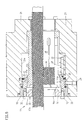
- the mold clamping unit has a stationary one Mold carrier 10, the position of which e.g. is fixed to the machine base and in the present case is indicated by a fixed bearing.
- a movable mold carrier provided, which in the present case is a structural Unit consisting of the platen 23, the cylinder 25 of the drive D and a clamping plate 24. Mold mounting plate 23 and clamping plate 24 are clamped together so that a precise on the guide elements 12th results guided unit that forms the movable mold carrier 11.
- the platen 23 of the movable mold carrier 11 and the stationary mold carrier 10 enclose the mold clamping space R between them.
- a drive D is provided for moving the movable mold carrier the movable mold carrier in the closing direction s-s on the stationary mold carrier 10 moved to and from this. Part of this drive D is in addition to Cylinders 25, the piston rod 26.
- a three-plate system (stationary mold carrier, movable mold carrier, support element) supports the piston rod 26 on the support element 21.
- the locking mechanism is conceivable to be arranged on the stationary mold carrier and thereby a two-platen system to get, with the facility to set the distance a is assigned to the stationary mold carrier 10 as a clamping device 13.
- the drive D which is hydraulic here, e.g. electromechanical or be pneumatic.
- guide elements 12 designed as guide columns (spars) in Figures 1 to 3, the stationary mold carrier 10 and the movable Mold carrier 11. They serve the movable mold carrier 11 during its Movement as a guide and can, as will be discussed in more detail below serve as a guide for the support element 21 during its movement, wherein this only requires a section 12a of the guide element 12, so that with other guidance of the movable mold carrier 11 to the rest Guide element can be omitted (Fig. 8).
- the support element 21 is in the Embodiment movable relative to the machine base in the closing direction s-s stored what is indicated by the symbol for the corresponding movable storage is indicated.
- the guide elements 12 have at least one section 12a with which the clamping device 13 comes into operative connection as soon as the desired distance a between stationary mold carrier 10 and movable Mold carrier 11 is set.
- a locking device 14 becomes the movable mold carrier 11 assigned to the movable mold carrier 11 in its respective when actuated Position.
- This setting can as in the embodiment the guide elements 12 take place, however, a definition is also conceivable of the movable mold carrier on the machine base or on another suitable one stationary position.
- the drive D which is usually part of the locking device for moving the movable mold carrier 11 and, if necessary to apply the closing force, when the locking device 14 and the support element 21, apart from the operative connection of the clamping device 13 along its guide, here along sections 12a of the guide elements 12 and move the distance a for the following spraying cycles change. This is shown in FIGS. 1 to 3.
- the distance a between the stationary mold carrier 10 and movable mold carrier 11 set by the drive D which at a small Injection mold with a low mold height cover a larger movement path must be as with an injection mold with a large mold height.
- an unchanged path of movement of the movable mold carrier 11 there is a change in distance a, like a comparison between 1 and 3 shows.
- the distance between the support element has also changed 21 and stationary mold carrier 10 and the length b of the üsr that Supporting element protruding guide elements 12.
- an adjusting device for adjusting the length b of the protruding ones Guide elements 12 while optimizing the amount of oil with unchanged movement path of the drive D are spoken.
- the locking device 14 only on any part be arranged of the movable mold carrier, wherein it is a single or can comprise several locking devices.
- the section 12a of the guide element 12 has a changed cross section on, this cross-sectional change should help that a positive connection with the clamping device 13 for fixing of the distance a can take place.
- a backlash-free form fit is at this point desirable because high forces have to be applied during the injection cycle, which the clamping device 13 must be up to.
- the cross-sectional change can be grooves or a thread 12b in the exemplary embodiment.
- a thread has the advantage that it is due to the continuous production can be produced very precisely when tapping.
- At the post office facility 14, on the other hand, is a non-positive determination, because during of the spray cycle this device is open and only during the secondary function the mold height adjustment low forces are applied for what the positive connection is sufficient.
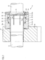
- Figures 4 and 5 show preferred embodiments of the clamping device 13 for the clearance-free determination of the distance a.
- an actuating element 15 is provided for a first collet 38, which is arranged coaxially to the guide elements 12 in the region of section 12a is.
- the collet has a threaded sleeve 16 which, when actuated the collet with the thread 12b of the section 12a in a form-fitting manner Active connection occurs.
- the clamping device 13 is constructed so that it automatically locked under the force of an elastic means 22 held on pins 37 Position remains. Unlocking for mold height adjustment or The distance a is changed under the action of a hydraulic medium.
- This hydraulic medium is via the hydraulic connection 29 in the annular hydraulic chamber 27 passed as a comparison between Fig. 4 and 5 illustrates, this hydraulic application leads to an axial movement of the annular piston 17 against the force of the elastic means 22 the conical section 17a of the annular piston 17 is disengaged and the tapered portion 16a of the collet 38 is engaged.
- the threaded sleeve 16 expanded by the cone ring 31 and a relative movement between support element 21 and guide element 12.
- Becomes the hydraulic pressure in the hydraulic chamber 27 is reduced as a result of elastic means mounted in the recess 21a of the support element 21 22 a return of the annular piston 17 into a position according to FIG.
- FIGs 6 and 7 show the locking device 14.
- This locking device 14 has a second collet 19, which in the exemplary embodiment is arranged coaxially to a guide element 12 and on the movable Mold carrier 11, more precisely on the clamping plate 24 in a recess 24a is fixed.
- the locking device has a housing 36 which a hydraulic chamber 28 encloses radially outward, which via a hydraulic connection 30 can be acted upon with hydraulic medium.
- the second Collet 19 has a conical region 19a, which is conical Section 18a of the hydraulically operated annular piston 18 die Clamping causes. The reset to the non-clamped position takes place here under the action of another elastic means 20.
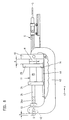
- Fig. 8 shows a further embodiment, which first clarifies that The piston rod 26 of the drive can also serve as a guide element via a section 26a, which in this respect corresponds to the previously mentioned section 12a is to be equated with the clamping device 13 in a positive operative connection occurs.
- Fig. 8 also shows that the use of the clamping device 13 and locking device 14 is also possible on a tie-bar-less machine, where instead of Guide columns a power transmission element 40 that occur during injection molding Forces around the mold clamping space R to achieve better accessibility around forwards.
- This possibly also multi-part power transmission element is articulated on the one hand on the stationary mold carrier 10.
- the movable mold carrier 11 associated end 42 of the drive D.
- the clamping device 13 can be provided, which cooperates with the section 26a. Is the Clamping device 13 opened and the one acting on the guide element 41 Locking device 14 can lock the drive D section 26a of the piston rod 26 move relative to the clamping device. This results in For the following injection cycles, the movement paths of the movable mold carrier have changed.
Landscapes
- Engineering & Computer Science (AREA)
- Manufacturing & Machinery (AREA)
- Mechanical Engineering (AREA)
- Moulds For Moulding Plastics Or The Like (AREA)
- Injection Moulding Of Plastics Or The Like (AREA)
Description
- Fig. 1
- Eine schematische Darstellung einer Spritzgießmaschine In Seitenansicht in Gebrauchsfunktion,
- Fig. 2
- die Spritzgießmaschine gemäß Fig. 1 mit verklemmten beweglichen Formträger,
- Fig. 3
- eine Darstellung gemäß Fig. 1 in Gebrauchsfunktion mit verstelltem Abstützelement,
- Fig. 4,5
- die Spannzange der Klemmeinrichtung zur Festlegung des Abstands a in geöffneter und geschlossener Stellung,
- Fig. 6,7
- die Feststelleinrichtung am beweglichen Formträger in geöffneter und verklemmter Stellung,
- Fig. 8
- ein Ausführungsbeispiel an einer holmlosen Spritzgießmaschine.
Claims (13)
- Formschließeinheit für eine Spritzgießmaschine zur Verarbeitung von Kunststoffen und anderer plastifizierbarer Massen, mitdadurch gekennzeichnet, dass sich wenigstens eines der beiden Teile des Antriebs (D) zur Bewegung des beweglichen Formträger (11) auch bei der Schließbewegung linear in Schließrichtung erstreckt.einem stationären Formträger (10),einem beweglichen Formträger (11), der zwischen sich und dem stationären Formträger (10) einen Formspannraum (R) zur Aufnahme von Spritzgießformen (M) veränderlicher Höhe, gemessen in einer Schließrichtung (s-s), aufweist,einem Antrieb (D) zum Bewegen des beweglichen Formträgers (11) in Schließrichtung (s-s) auf den stationären Formträger (10) zu und vom stationären Formträger weg, der wenigstens zwei miteinander in Wirkverbindung stehende Teile aufweist, von denen ein Teil an einem Abstützelement (21) abgestützt ist und das andere Teil mit dem beweglichen Formträger (11) verbunden ist,Führungselementen (12), die den beweglichen Formträger (11) während seiner Bewegung in Schließrichtung (s-s) führen, mit wenigstens einem Abschnitt (12a,26a),einer Einrichtung zur veränderlichen Festlegung des Abstands (a) zwischen stationärem Formträger (10) und beweglichem Formträger (11) gemessen bei geschlossener Spritzgießform (M) und unter Annahme eines gegenüber dem Zustand vor Veränderung des Abstands (a) unveränderten Bewegungswegs des beweglichen Formträgers in Form einer klemmeinrichtung (13), welche Klemmeinrichtung (13) zur Festlegung des eingestellten Abstandes (a) mit dem Abschnitt (12a,26a) der Führungselemente (12) in formschlüssige Wirkverbindung tritt,einer dem beweglichen Formträger (11) zugeordneten Feststelleinrichtung (14), die bei Betätigung den beweglichen Formträger (11) in seiner jeweiligen Stellung festlegt,wobei der Antrieb (D) selbst bei betätigter Feststelleinrichtung (14) und außer Wirkverbindung befindlicher Ktemmeinrichtung (13) den Abstand (a) durch Verschieben der Klemmeinrichtung (13) entlang des Abschnittes (12a,26a) verändert,
- Formschließeinheit nach Anspruch 1, dadurch gekennzeichnet, dass der Antrieb (D) ein Hydraulikantrieb ist und dass die Teile des Antriebs (D) Zylinder (25) und Kolbenstange (26) einer hydraulischen Kolben-Zylinder-Einheit sind.
- Formschließeinheit nach Anspruch 1, dadurch gekennzeichnet, dass der Antrieb (D) ein elektromechanischer Antrieb.
- Formschließeinheit nach Anspruch 1, dadurch gekennzeichnet, dass der Abstand (a) unter wechselweiser Betätigung von Klemmeinrichtung (13) und Feststelleinrichtung (14) in Verbindung mit dem Antrieb (D) veränderbar ist.
- Formschließeinheit nach Anspruch 1, dadurch gekennzeichnet, dass die Klemmeinrichtung (13) eine erste Spannzange (37) aufweist, die koaxial zum Führungselement (12) im Bereich des Abschnitts (12a) angeordnet ist und mit dem Abschnitt (12a) in formschlüssige, spielfreie Wirkverbindung überführbar ist.
- Formschließeinheit nach Anspruch 5, dadurch gekennzeichnet, daß die erste Spannzange (38) einen konusförmigen Bereich (16a) aufweist, der zur Lösung der Spannung hydraulisch in Wirkverbindung mit einem mit einem Ringkolben (17) verbundenen Konusring (31) und unter der Kraft eines elastischen Mittels (22) außer Wirkverbindung mit dem Konusring kommt, wobei der Ringkolben (17) entlang des Führungselement (12) begrenzt axial beweglich ist.
- Formschließeinheit nach Anspruch 1, dadurch gekennzeichnet, daß derAbschnitt (12a) der Führungselemente (12) zur formschlüssigen Wirkverbindung mit einer Gewindehülse (16) der Klemmeinrichtung (13) ein Gewinde (12b) aufweist.
- Formschließeinheit nach Anspruch 1, dadurch gekennzeichnet, daß die betätigte Feststelleinrichtung (14) den beweglichen Formträger (11) an den Führungselementen (12) kraftschlüssig festlegt.
- Formschließeinheit nach Anspruch 1, dadurch gekennzeichnet, daß die Feststelleinrichtung (14) eine zweite Spannzange (19) aufweist, die koaxial zu einem Führungselement (12) angeordnet und am beweglichen Formträger (11) festgelegt ist.
- Formschließeinheit nach Anspruch 9, dadurch gekennzeichnet, daß die zweite Spannzange (19) einen konusförmigen Bereich (19a) aufweist und daß ein zweiter hydraulisch betätigter Ringkolben (18) mit einem konusförmigen Abschnitt (18a) bei hydraulischer Beaufschlagung die Klemmung mit dem konusförmigen Bereich (19a) bewirkt, welcher Ringkolben (18) vorzugsweise über ein weiteres elastisches Element (20) rückstellbar ist.
- Formschließeinheit nach Anspruch 1, dadurch gekennzeichnet, daß die Klemmeinrichtung (13) dem Abstützelement (21) zugeordnet ist.
- Formschließeinheit nach Anspruch 1, dadurch gekennzeichnet, daß das Führungselement eine Kolbenstange (26) des Antriebs ist, die über einen Abschnitt (26a) mit der Klemmeinrichtung (13) in Wirkverbindung tritt.
- Formschließeinheit nach Anspruch 1, dadurch gekennzeichnet, daß am stationären Formträger (10) ein Kraftübertragungselement (40) angelenkt ist, an dessen gegenüberliegenden, dem beweglichen Formträger (11) zugeordneten Ende (42) die Klemmeinrichtung (13) angeordnet ist, die mit dem Abschnitt (26a) zusammenwirkt.
Applications Claiming Priority (3)
| Application Number | Priority Date | Filing Date | Title |
|---|---|---|---|
| DE19812741 | 1998-03-24 | ||
| DE19812741A DE19812741B4 (de) | 1998-03-24 | 1998-03-24 | Formschließeinheit für eine Spritzgießmaschine |
| PCT/EP1999/001869 WO1999048667A1 (de) | 1998-03-24 | 1999-03-20 | Formschliesseinheit für eine spritzgiessmaschine |
Publications (2)
| Publication Number | Publication Date |
|---|---|
| EP1068060A1 EP1068060A1 (de) | 2001-01-17 |
| EP1068060B1 true EP1068060B1 (de) | 2002-09-11 |
Family
ID=7862005
Family Applications (1)
| Application Number | Title | Priority Date | Filing Date |
|---|---|---|---|
| EP99915677A Expired - Lifetime EP1068060B1 (de) | 1998-03-24 | 1999-03-20 | Formschliesseinheit für eine spritzgiessmaschine |
Country Status (6)
| Country | Link |
|---|---|
| EP (1) | EP1068060B1 (de) |
| JP (1) | JP2002507499A (de) |
| AT (1) | ATE223795T1 (de) |
| CA (1) | CA2325456A1 (de) |
| DE (2) | DE19812741B4 (de) |
| WO (1) | WO1999048667A1 (de) |
Cited By (3)
| Publication number | Priority date | Publication date | Assignee | Title |
|---|---|---|---|---|
| EP1886789B1 (de) | 2005-06-02 | 2016-01-20 | Sumitomo Heavy Industries, Ltd. | Verfahren zur einstellung von spritzgiessbedingungen und formschliessvorrichtung |
| DE102017223822A1 (de) | 2017-12-27 | 2019-06-27 | Arburg Gmbh + Co. Kg | Formschließeinheit für eine Spritzgießmaschine sowie Verfahren zum Verriegeln eines Kraftübertragungselements |
| DE102018124608A1 (de) * | 2018-10-05 | 2020-04-09 | Arburg Gmbh + Co Kg | Formschließeinheit für eine Spritzgießmaschine sowie Verfahren zum Verriegeln eines Kraftübertragungselements |
Families Citing this family (8)
| Publication number | Priority date | Publication date | Assignee | Title |
|---|---|---|---|---|
| EP1086798A1 (de) * | 1999-09-22 | 2001-03-28 | Karl Hehl | Formschliesseinheit für eine Spritzgiessmaschine |
| US6719553B1 (en) | 1998-03-24 | 2004-04-13 | Karl Hehl | Mold-closing unit for an injection molding machine |
| DE10003711A1 (de) * | 2000-01-28 | 2001-08-02 | Mayr Christian Gmbh & Co Kg | Spannkupplung |
| DE10210869C1 (de) | 2002-03-12 | 2003-07-17 | Karl Hehl | Formschliesseinheit mit einer Formhöhenverstellung sowie Verfahren zu deren Betätigung |
| JP3629479B2 (ja) | 2002-07-17 | 2005-03-16 | ファナック株式会社 | 射出成形機の型厚調整機構 |
| JP5766673B2 (ja) | 2012-09-11 | 2015-08-19 | 住友重機械工業株式会社 | 射出成形機 |
| DE102016119840A1 (de) | 2016-10-18 | 2018-04-19 | Arburg Gmbh + Co Kg | Formschließeinheit mit einer Formhöhenverstellung sowie Verfahren zu deren Betätigung |
| CN112549472B (zh) * | 2020-11-25 | 2022-08-02 | 合肥尚德新能源科技有限公司 | 一种注塑机合模装置及其使用方法 |
Family Cites Families (4)
| Publication number | Priority date | Publication date | Assignee | Title |
|---|---|---|---|---|
| DE3042712A1 (de) * | 1980-11-13 | 1982-06-24 | Karl 7298 Loßburg Hehl | Formenschliesseinheit einer spritzgiessmaschine |
| US4281977A (en) * | 1979-10-01 | 1981-08-04 | Package Machinery Company | Apparatus for setting a clamping load |
| JPH04169216A (ja) * | 1990-11-02 | 1992-06-17 | Fanuc Ltd | 射出成形機の型厚調整方法 |
| JP2704572B2 (ja) * | 1991-12-26 | 1998-01-26 | 日精樹脂工業株式会社 | 成形機の型締装置 |
-
1998
- 1998-03-24 DE DE19812741A patent/DE19812741B4/de not_active Expired - Fee Related
-
1999
- 1999-03-20 DE DE59902655T patent/DE59902655D1/de not_active Expired - Lifetime
- 1999-03-20 EP EP99915677A patent/EP1068060B1/de not_active Expired - Lifetime
- 1999-03-20 WO PCT/EP1999/001869 patent/WO1999048667A1/de not_active Ceased
- 1999-03-20 CA CA002325456A patent/CA2325456A1/en not_active Abandoned
- 1999-03-20 AT AT99915677T patent/ATE223795T1/de not_active IP Right Cessation
- 1999-03-20 JP JP2000537695A patent/JP2002507499A/ja not_active Withdrawn
Cited By (6)
| Publication number | Priority date | Publication date | Assignee | Title |
|---|---|---|---|---|
| EP1886789B1 (de) | 2005-06-02 | 2016-01-20 | Sumitomo Heavy Industries, Ltd. | Verfahren zur einstellung von spritzgiessbedingungen und formschliessvorrichtung |
| DE102017223822A1 (de) | 2017-12-27 | 2019-06-27 | Arburg Gmbh + Co. Kg | Formschließeinheit für eine Spritzgießmaschine sowie Verfahren zum Verriegeln eines Kraftübertragungselements |
| WO2019129670A1 (de) | 2017-12-27 | 2019-07-04 | Arburg Gmbh + Co Kg | Formschliesseinheit für eine spritzgiessmaschine sowie verfahren zum verriegeln eines kraftübertragungselements |
| US11247375B2 (en) | 2017-12-27 | 2022-02-15 | Arburg Gmbh + Co Kg | Mould-closing unit for an injection moulding machine, and method for locking a force transmission element |
| DE102018124608A1 (de) * | 2018-10-05 | 2020-04-09 | Arburg Gmbh + Co Kg | Formschließeinheit für eine Spritzgießmaschine sowie Verfahren zum Verriegeln eines Kraftübertragungselements |
| US11931940B2 (en) | 2018-10-05 | 2024-03-19 | Arburg Gmbh + Co Kg | Mold-closing unit for an injection molding machine, and method for locking a force transmission element |
Also Published As
| Publication number | Publication date |
|---|---|
| JP2002507499A (ja) | 2002-03-12 |
| WO1999048667A1 (de) | 1999-09-30 |
| EP1068060A1 (de) | 2001-01-17 |
| ATE223795T1 (de) | 2002-09-15 |
| CA2325456A1 (en) | 1999-09-30 |
| DE59902655D1 (de) | 2002-10-17 |
| DE19812741B4 (de) | 2005-04-28 |
| DE19812741A1 (de) | 1999-09-30 |
Similar Documents
| Publication | Publication Date | Title |
|---|---|---|
| DE4344340C2 (de) | Formschließvorrichtung für eine Spritzgießmaschine | |
| DE2113414A1 (de) | Schliess-,Verriegelungs- und Vorspann-Vorrichtung fuer Giessformen | |
| EP1068060B1 (de) | Formschliesseinheit für eine spritzgiessmaschine | |
| EP3655225B1 (de) | Formschliesseinheit für eine spritzgiessmaschine | |
| EP3529029B1 (de) | Formschliesseinheit mit einer formhöhenverstellung sowie verfahren zu deren betätigung | |
| EP1487626B1 (de) | Formschliesseinheit mit einer formhöhenverstellung sowie verfahren zu deren betätigung | |
| CH417064A (de) | Spritzgussmaschine für thermoplastische Kunststoffe | |
| EP1802441B1 (de) | Schliesseinheit für eine spritzgiessmaschine mit etagenwerkzeug | |
| EP1237704A1 (de) | Vorrichtung und verfahren zur durchführung einer zweistufigen linearen bewegung | |
| EP0585671B1 (de) | Auswerfereinheit für Spritzgiessmaschinen | |
| EP0314942B1 (de) | Verriegelungseinrichtung für den Plastifizierzylinder einer Kunststoff-Spritzgiessmaschine | |
| DE102008023720B3 (de) | Formschließeinheit einer Spritzgießmaschine | |
| DE19535081C2 (de) | Zwei-Platten-Spritzgießmaschine | |
| EP1512512B1 (de) | Spritzgiessvorrichtung | |
| EP0421088A2 (de) | Formschliessvorrichtung für eine Spritzgiessmaschine | |
| DE19945287A1 (de) | Formschliesseinheit für eine Spritzgiessmaschine | |
| DE2102725A1 (en) | Injection mould closure - with lightweight ram uses locking bars and mechanisms to provide closure force | |
| EP2125326A1 (de) | Verfahren zum betreiben einer spritzgiessmaschine mit zwei kniehebelmechanismen sowie zugehörige spritzgiessmaschine | |
| EP1086798A1 (de) | Formschliesseinheit für eine Spritzgiessmaschine | |
| DE4446692A1 (de) | Formschließeinrichtung für Kunststoffspritzgießmaschinen | |
| DE19615122C1 (de) | Schließeinheit für eine Kunststoff-Spritzgießmachine | |
| DE102020107538B4 (de) | Formgebungsmaschine und/oder Baugruppe für eine Formgebungsmaschine und Verfahren zum Einstellen der Länge einer Zug- oder Druckstange einer Formgebungsmaschine und/oder einer Baugruppe | |
| DE102024105264A1 (de) | Schließeinheit sowie Formgebungsmaschine mit einer solchen Schließeinheit | |
| DE1583703B1 (de) | Vorrichtung zur Begrenzung des OEffnungshubes hydraulisch bewegter Formtraegereinheiten von Spritzgiessmaschinen | |
| DE19847306C1 (de) | Vorrichtung zum Anpassen einer Kunststoffverarbeitungsmaschine, insbesondere Blasformmaschine, an unterschiedliche Formdicken |
Legal Events
| Date | Code | Title | Description |
|---|---|---|---|
| PUAI | Public reference made under article 153(3) epc to a published international application that has entered the european phase |
Free format text: ORIGINAL CODE: 0009012 |
|
| 17P | Request for examination filed |
Effective date: 20000921 |
|
| AK | Designated contracting states |
Kind code of ref document: A1 Designated state(s): AT CH DE FR GB IT LI |
|
| GRAG | Despatch of communication of intention to grant |
Free format text: ORIGINAL CODE: EPIDOS AGRA |
|
| 17Q | First examination report despatched |
Effective date: 20011120 |
|
| GRAG | Despatch of communication of intention to grant |
Free format text: ORIGINAL CODE: EPIDOS AGRA |
|
| GRAH | Despatch of communication of intention to grant a patent |
Free format text: ORIGINAL CODE: EPIDOS IGRA |
|
| GRAH | Despatch of communication of intention to grant a patent |
Free format text: ORIGINAL CODE: EPIDOS IGRA |
|
| GRAA | (expected) grant |
Free format text: ORIGINAL CODE: 0009210 |
|
| AK | Designated contracting states |
Kind code of ref document: B1 Designated state(s): AT CH DE FR GB IT LI |
|
| PG25 | Lapsed in a contracting state [announced via postgrant information from national office to epo] |
Ref country code: IT Free format text: LAPSE BECAUSE OF FAILURE TO SUBMIT A TRANSLATION OF THE DESCRIPTION OR TO PAY THE FEE WITHIN THE PRE;WARNING: LAPSES OF ITALIAN PATENTS WITH EFFECTIVE DATE BEFORE 2007 MAY HAVE OCCURRED AT ANY TIME BEFORE 2007. THE CORRECT EFFECTIVE DATE MAY BE DIFFERENT FROM THE ONE RECORDED.SCRIBED TIME-LIMIT Effective date: 20020911 Ref country code: GB Free format text: LAPSE BECAUSE OF FAILURE TO SUBMIT A TRANSLATION OF THE DESCRIPTION OR TO PAY THE FEE WITHIN THE PRESCRIBED TIME-LIMIT Effective date: 20020911 Ref country code: FR Free format text: LAPSE BECAUSE OF NON-PAYMENT OF DUE FEES Effective date: 20020911 |
|
| REF | Corresponds to: |
Ref document number: 223795 Country of ref document: AT Date of ref document: 20020915 Kind code of ref document: T |
|
| REG | Reference to a national code |
Ref country code: GB Ref legal event code: FG4D Free format text: NOT ENGLISH |
|
| REG | Reference to a national code |
Ref country code: CH Ref legal event code: EP |
|
| REG | Reference to a national code |
Ref country code: CH Ref legal event code: NV Representative=s name: LUCHS & PARTNER PATENTANWAELTE |
|
| REF | Corresponds to: |
Ref document number: 59902655 Country of ref document: DE Date of ref document: 20021017 |
|
| GBV | Gb: ep patent (uk) treated as always having been void in accordance with gb section 77(7)/1977 [no translation filed] |
Effective date: 20020911 |
|
| PGFP | Annual fee paid to national office [announced via postgrant information from national office to epo] |
Ref country code: CH Payment date: 20030324 Year of fee payment: 5 |
|
| EN | Fr: translation not filed | ||
| PLBE | No opposition filed within time limit |
Free format text: ORIGINAL CODE: 0009261 |
|
| STAA | Information on the status of an ep patent application or granted ep patent |
Free format text: STATUS: NO OPPOSITION FILED WITHIN TIME LIMIT |
|
| 26N | No opposition filed |
Effective date: 20030612 |
|
| PG25 | Lapsed in a contracting state [announced via postgrant information from national office to epo] |
Ref country code: LI Free format text: LAPSE BECAUSE OF NON-PAYMENT OF DUE FEES Effective date: 20040331 Ref country code: CH Free format text: LAPSE BECAUSE OF NON-PAYMENT OF DUE FEES Effective date: 20040331 |
|
| REG | Reference to a national code |
Ref country code: CH Ref legal event code: PL |
|
| PGFP | Annual fee paid to national office [announced via postgrant information from national office to epo] |
Ref country code: AT Payment date: 20060324 Year of fee payment: 8 |
|
| PG25 | Lapsed in a contracting state [announced via postgrant information from national office to epo] |
Ref country code: AT Free format text: LAPSE BECAUSE OF NON-PAYMENT OF DUE FEES Effective date: 20070320 |
|
| PGFP | Annual fee paid to national office [announced via postgrant information from national office to epo] |
Ref country code: DE Payment date: 20120217 Year of fee payment: 14 |
|
| REG | Reference to a national code |
Ref country code: DE Ref legal event code: R119 Ref document number: 59902655 Country of ref document: DE Effective date: 20131001 |
|
| PG25 | Lapsed in a contracting state [announced via postgrant information from national office to epo] |
Ref country code: DE Free format text: LAPSE BECAUSE OF NON-PAYMENT OF DUE FEES Effective date: 20131001 |