EP1067530A2 - Optische Aufzeichnungs/Wiedergabevorrichtung, optisches System dafür und Koppellinse - Google Patents
Optische Aufzeichnungs/Wiedergabevorrichtung, optisches System dafür und Koppellinse Download PDFInfo
- Publication number
- EP1067530A2 EP1067530A2 EP00114312A EP00114312A EP1067530A2 EP 1067530 A2 EP1067530 A2 EP 1067530A2 EP 00114312 A EP00114312 A EP 00114312A EP 00114312 A EP00114312 A EP 00114312A EP 1067530 A2 EP1067530 A2 EP 1067530A2
- Authority
- EP
- European Patent Office
- Prior art keywords
- optical
- optical system
- light flux
- light source
- lens
- Prior art date
- Legal status (The legal status is an assumption and is not a legal conclusion. Google has not performed a legal analysis and makes no representation as to the accuracy of the status listed.)
- Withdrawn
Links
Images


Classifications
-
- G—PHYSICS
- G11—INFORMATION STORAGE
- G11B—INFORMATION STORAGE BASED ON RELATIVE MOVEMENT BETWEEN RECORD CARRIER AND TRANSDUCER
- G11B7/00—Recording or reproducing by optical means, e.g. recording using a thermal beam of optical radiation by modifying optical properties or the physical structure, reproducing using an optical beam at lower power by sensing optical properties; Record carriers therefor
- G11B7/12—Heads, e.g. forming of the optical beam spot or modulation of the optical beam
- G11B7/135—Means for guiding the beam from the source to the record carrier or from the record carrier to the detector
- G11B7/1353—Diffractive elements, e.g. holograms or gratings
-
- G—PHYSICS
- G02—OPTICS
- G02B—OPTICAL ELEMENTS, SYSTEMS OR APPARATUS
- G02B3/00—Simple or compound lenses
- G02B3/10—Bifocal lenses; Multifocal lenses
-
- G—PHYSICS
- G02—OPTICS
- G02B—OPTICAL ELEMENTS, SYSTEMS OR APPARATUS
- G02B27/00—Optical systems or apparatus not provided for by any of the groups G02B1/00 - G02B26/00, G02B30/00
- G02B27/10—Beam splitting or combining systems
-
- G—PHYSICS
- G02—OPTICS
- G02B—OPTICAL ELEMENTS, SYSTEMS OR APPARATUS
- G02B27/00—Optical systems or apparatus not provided for by any of the groups G02B1/00 - G02B26/00, G02B30/00
- G02B27/10—Beam splitting or combining systems
- G02B27/1086—Beam splitting or combining systems operating by diffraction only
- G02B27/1093—Beam splitting or combining systems operating by diffraction only for use with monochromatic radiation only, e.g. devices for splitting a single laser source
-
- G—PHYSICS
- G02—OPTICS
- G02B—OPTICAL ELEMENTS, SYSTEMS OR APPARATUS
- G02B27/00—Optical systems or apparatus not provided for by any of the groups G02B1/00 - G02B26/00, G02B30/00
- G02B27/10—Beam splitting or combining systems
- G02B27/14—Beam splitting or combining systems operating by reflection only
- G02B27/145—Beam splitting or combining systems operating by reflection only having sequential partially reflecting surfaces
-
- G—PHYSICS
- G02—OPTICS
- G02B—OPTICAL ELEMENTS, SYSTEMS OR APPARATUS
- G02B5/00—Optical elements other than lenses
- G02B5/18—Diffraction gratings
- G02B5/1876—Diffractive Fresnel lenses; Zone plates; Kinoforms
-
- G—PHYSICS
- G02—OPTICS
- G02B—OPTICAL ELEMENTS, SYSTEMS OR APPARATUS
- G02B5/00—Optical elements other than lenses
- G02B5/18—Diffraction gratings
- G02B5/1876—Diffractive Fresnel lenses; Zone plates; Kinoforms
- G02B5/189—Structurally combined with optical elements not having diffractive power
-
- G—PHYSICS
- G11—INFORMATION STORAGE
- G11B—INFORMATION STORAGE BASED ON RELATIVE MOVEMENT BETWEEN RECORD CARRIER AND TRANSDUCER
- G11B7/00—Recording or reproducing by optical means, e.g. recording using a thermal beam of optical radiation by modifying optical properties or the physical structure, reproducing using an optical beam at lower power by sensing optical properties; Record carriers therefor
- G11B7/12—Heads, e.g. forming of the optical beam spot or modulation of the optical beam
- G11B7/135—Means for guiding the beam from the source to the record carrier or from the record carrier to the detector
- G11B7/1356—Double or multiple prisms, i.e. having two or more prisms in cooperation
-
- G—PHYSICS
- G11—INFORMATION STORAGE
- G11B—INFORMATION STORAGE BASED ON RELATIVE MOVEMENT BETWEEN RECORD CARRIER AND TRANSDUCER
- G11B7/00—Recording or reproducing by optical means, e.g. recording using a thermal beam of optical radiation by modifying optical properties or the physical structure, reproducing using an optical beam at lower power by sensing optical properties; Record carriers therefor
- G11B7/12—Heads, e.g. forming of the optical beam spot or modulation of the optical beam
- G11B7/135—Means for guiding the beam from the source to the record carrier or from the record carrier to the detector
- G11B7/1372—Lenses
- G11B7/1376—Collimator lenses
-
- G—PHYSICS
- G11—INFORMATION STORAGE
- G11B—INFORMATION STORAGE BASED ON RELATIVE MOVEMENT BETWEEN RECORD CARRIER AND TRANSDUCER
- G11B7/00—Recording or reproducing by optical means, e.g. recording using a thermal beam of optical radiation by modifying optical properties or the physical structure, reproducing using an optical beam at lower power by sensing optical properties; Record carriers therefor
- G11B7/12—Heads, e.g. forming of the optical beam spot or modulation of the optical beam
- G11B7/135—Means for guiding the beam from the source to the record carrier or from the record carrier to the detector
- G11B7/139—Numerical aperture control means
-
- G—PHYSICS
- G11—INFORMATION STORAGE
- G11B—INFORMATION STORAGE BASED ON RELATIVE MOVEMENT BETWEEN RECORD CARRIER AND TRANSDUCER
- G11B7/00—Recording or reproducing by optical means, e.g. recording using a thermal beam of optical radiation by modifying optical properties or the physical structure, reproducing using an optical beam at lower power by sensing optical properties; Record carriers therefor
- G11B7/12—Heads, e.g. forming of the optical beam spot or modulation of the optical beam
- G11B7/135—Means for guiding the beam from the source to the record carrier or from the record carrier to the detector
- G11B7/1392—Means for controlling the beam wavefront, e.g. for correction of aberration
- G11B7/13922—Means for controlling the beam wavefront, e.g. for correction of aberration passive
-
- G—PHYSICS
- G11—INFORMATION STORAGE
- G11B—INFORMATION STORAGE BASED ON RELATIVE MOVEMENT BETWEEN RECORD CARRIER AND TRANSDUCER
- G11B7/00—Recording or reproducing by optical means, e.g. recording using a thermal beam of optical radiation by modifying optical properties or the physical structure, reproducing using an optical beam at lower power by sensing optical properties; Record carriers therefor
- G11B2007/0003—Recording, reproducing or erasing systems characterised by the structure or type of the carrier
- G11B2007/0006—Recording, reproducing or erasing systems characterised by the structure or type of the carrier adapted for scanning different types of carrier, e.g. CD & DVD
Definitions
- the present invention relates to an optical pickup apparatus used for recording and/or reproducing for optical-information-recording medium, a recording/reproducing apparatus for an optical information recording medium, a light-converging optical system and a coupling lens. It relates, in particular, to an optical pickup apparatus, a recording/reproducing apparatus for an optical information recording medium, a light-converging optical system and a coupling lens, wherein a numerical aperture is large and temperature characteristics are excellent in spite of an objective lens optical system including a lens made of resin materials.
- An optical pickup apparatus for reproduction of DVD lacks its practicality, unless it conducts reproduction of CD and CD-R too.
- DVD and CD are different each other in terms of a thickness of a transparent base board and of numerical aperture NA of an objective lens on the part of an optical information recording medium.
- CD-R absorbs light having a wavelength of 635 nm - 660 nm, which makes it necessary for the optical pickup apparatus to be provided with two lasers including a laser with a wavelength of 635 nm - 660 nm and a laser with a wavelength of 780 nm.
- ⁇ T a temperature difference between an ambient temperature used actually and a standard design temperature
- ⁇ T an amount of change of wavefront aberration caused by this temperature difference ⁇ T is mainly a spherical aberration component
- ⁇ Wo numerical aperture of an objective lens on the part of optical information recording medium (on the part of an image)
- NA numerical aperture of an objective lens on the part of optical information recording medium (on the part of an image)
- f a focal length
- M a lateral magnification
- ⁇ Wo ⁇ ⁇ ⁇ NA ⁇ (1 - M) ⁇ 4 ⁇ f ⁇ ⁇ T
- a two-layer DVD disk having great capacity is spreading, and two layers are arranged to be away from each other by a distance of about 0.05 mm. Accordingly, although spherical aberration is zero for reproduction of a layer on one side, spherical aberration caused by a difference in a distance from the surface of a base board exists for the layer on the other side.
- the coupling optical system including a lens made of resin material having positive refracting power.
- the coupling optical system is a coupling lens which is made of one piece of resin material and has positive refracting power in one occasion, and it is a coupling optical system which includes a glass-made lens having negative refracting power in addition to a lens which is made of resin material and has positive refracting power in the other occasion.
- the zonal diffraction surface having negative diffraction power means a diffraction surface which is formed in a concentric and zonal pattern when viewed in the optical axis direction, and when a light flux emitted from a light source enters this diffraction surface directly or indirectly through other optical elements (lens, prism and filter), this diffraction surface has negative diffraction power against the incident light flux, in other words, the diffraction surface operates to diverge the light flux more.
- the concentric and zonal pattern means one which looks like a concentric and zonal shape around an optical axis or its neighboring portion.
- the diffraction surface When the diffraction surface is provided on the surface having refracting power, it means that the diffraction light caused by the minute structure (for example, a serrated relief shape) for diffraction itself has the aforesaid diverging action for the incident light flux.
- the minute structure for example, a serrated relief shape
- the diffraction light caused by the minute structure for example, a serrated relief shape
- the diffraction light caused by the minute structure for diffraction itself has the aforesaid diverging action for the incident light flux.
- This can be confirmed by assuming (for example, assuming by means of simulation) an optical surface representing an enveloped minute structure for diffraction and by comparing this with a light flux caused by refraction of the assumed optical surface, and when a light flux by the zonal diffraction surface having refracting power is diverged to expand a light flux by the aforesaid assumed optical surface like forming a minute structure for diffraction on
- a surface having refracting power means a surface having a portion to change a divergent angle of a light flux at least on a part of its surface, and it includes, for example, occasions wherein an optical axis and its neighboring portion form a pattern of the surface that is mostly perpendicular to the optical axis, and a sign of refracting power is opposite to that of desired refracting power.
- objective lens optical system represents, in a narrow sense, a lens system having light-converging action which is arranged oppositely at the position closest to an optical information recording medium, and it represents, in a wide sense, a lens system which is arranged at the position facing an optical information recording medium and can be moved by an actuator at least in the optical axis direction.
- Coupled optical system represents a lens system which is structured separately from the objective lens optical system and has an action to change a divergent angle of a light flux when a divergent light flux emitted from a light source enters the coupling optical system directly or indirectly, and for example, it includes the so-called collimating optical system which turns a divergent light flux emitted from a light source into a collimated light flux which is mostly in parallel with an optical axis.
- a zonal diffraction surface having negative diffraction power (having an action to diverge a light flux emitted from a light source) can be the surface on one side of a resin-made lens having positive refracting power which is included in the aforesaid coupling optical system, which is preferable because it is possible to realize a low price by reducing the number of optical elements including lenses.
- the coupling optical system prefferably be a collimating optical system which turns an incident divergent light flux into a light flux that is mostly in parallel with an optical axis.
- the objective lens optical system and/or the coupling optical system mentioned above can be a single lens, and in that case, it is possible to realize a low price as in the foregoing, and to make a light-converging optical system to be small in size, which is preferable.
- a coupling lens is made of resin material for an objective lens made of resin material, fluctuation in spherical aberration is smaller compared with an occasion where a coupling lens is made of glass material, in the case of a total light-converging optical system for recording on and/or reproducing from an optical information recording medium (for example, see TOKKAIHEI No. 9-138344).
- a coupling lens there is used a collimator lens which converts a light flux emitted from a light source into a collimated light flux having no aberration.
- a light emitting point of a light source and a focal point of a collimator lens on the part of a light source agree with each other at the standard designed temperature, and a collimated light flux emerges from the collimator lens.
- the collimator lens is made of resin material, a focal length of the collimator lens is caused to be longer when temperature rises. Namely, the focal point is shifted in the optical axis direction to be farther than the light emitting point from the collimator lens. As a result, a light flux that emerges from the collimator lens is turned into a divergent light.
- an aspherical objective lens composed of a resin-made single lens which is designed and manufactured to have no aberration when a collimated light flux enters the aspherical objective lens, spherical aberration moves toward its under level when a divergent light flux enters the aspherical objective lens.
- ⁇ M can be expressed by the following expression, when proportional constant ⁇ is smaller than zero, and temperature change rate of collimator lens back focus f bc of collimator lens is represented by d f bc/dT.
- ⁇ M ⁇ ⁇ d f bc / dT ⁇ ⁇ T
- the collimator lens is a lens which is made of resin material and has positive refracting power, and its surface on at least one side thereof needs to be a zonal diffraction surface having negative diffraction power (having an action to diverge a light flux emitted from a light source).
- a focal length is highly dependent on a wavelength.
- a light source is a semiconductor laser
- an oscillated wavelength is temperature-dependent, and the higher the temperature is, the longer the wavelength is.
- d ⁇ /dT 0.2 nm/°C
- a change in power of a collimator lens caused when a wavelength is changed by ⁇ is as follows.
- the sum of the first term and the second term is also negative, and wave-dependency of a semiconductor laser further increases an effect of the invention.
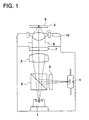
- the optical pickup apparatus in Fig. 1 is equipped with semiconductor laser 1 representing a light source, coupling lens 2 which converts a divergent angle of a divergent light emitted from the light source, objective lens optical system 3 which converges a light flux coming from the coupling lens on an information recording surface of an optical information recording medium, and with optical detection unit 4 which receives reflected light from the optical information recording medium.
- the numeral 5 represents an information recording surface of the optical information recording medium
- 6 represents a beam splitter which divides the reflected light
- 7 represents 1/4 wavelength plate
- 8 represents a diaphragm
- 9 represents a cylindrical lens
- 10 represents an actuator for focus tracking.
- the objective lens optical system 3 includes a lens which is formed by at least one sheet of resin material and has positive refracting power
- the coupling lens 2 is formed by resin material and it is a lens having positive refracting power in which a surface on at least one side of the lens has a zonal diffraction surface having negative diffraction power (having an action to diverge a light flux emitted from a light source).
- the coupling lens 2 may also be a collimator lens which causes an incident divergent light flux to be a light flux which is mostly in parallel with an optical axis, and in this case, it is preferable that a light source or the collimator lens is moved in the direction of the optical axis for adjustment so that a light flux emerging from the collimator lens may become a mostly-collimated light.
- a coupling optical system is composed only of coupling lens 2, and an objective lens optical system is composed only of objective lens 3.
- the coupling optical system may also have a plurality of lenses and a beam splitter, and the objective lens optical system may also have a plurality of lenses.
- first light source 11 for recording on and/or reproducing from the first optical information recording medium
- second light source 12 which is different from the first light source 11 in terms of wavelength and records on and/or reproduces from the second optical information recording medium
- two coupling lenses 21 and 22 each converting a divergent angle of a divergent light flux emitted from each of light sources into a desired divergent angle
- beam splitter 62 representing a light composing means which composes the light fluxes so that they advance in the same direction
- objective lens optical system 3 which converges a light flux from the beam splitter 62 on information recording surface 5 of the optical information recording medium
- optical detection units 41 and 42 each receiving reflected light from the optical information recording medium.
- the numeral 8 represents a diaphragm
- 71 and 72 represent 1/4 wavelength plate
- 15 represents a coupling lens which makes an extent of detergence of a detergent light flux emitted from light source 11 to be small
- 16 represents a concave lens
- 17 represents a hologram for dividing a reflected light flux.
- an actuator for focus tracking is omitted.
- the objective lens optical system 3 includes a lens which is formed by at least on sheet of resin material and has positive refracting power, and at least one of the coupling lenses 21 and 22, for example, the coupling lens 21 is made to be a lens made of resin material and having positive refracting power wherein at least one surface thereof has a zonal diffraction surface having negative diffraction power (having an action to further diverge a light flux emitted from a light source).
- an aperture limiting means which transmits a light flux emitted from the first light source and does not transmit a light flux which passes through a prescribed area that is away from an optical axis among a light flux emitted from the second light source.
- the aperture limiting means which does not transmit a light flux passing through a prescribed area is one which does not make a light flux passing through the prescribed area to form an image at least on an ordinary image forming position, and one which can limit an aperture substantially is acceptable, and there is given the following embodiment.
- This aperture limiting means may be either a zonal filter which transmits a light flux emitted from the first light source, and reflects or absorbs a light flux passing through an area being away from an optical axis among a alight flux emitted from the second light source, or a zonal filter which transmits a light flux emitted from the first light source and diffracts a light flux passing through an area being away from an optical axis of the diffraction pattern among a light flux emitted from the second light source.
- second semiconductor laser 12 is unitized with optical detection unit 42 and with hologram 17.
- "Unit” or “unitization” means that unitized members and means are arranged to be incorporated integrally in an optical pickup apparatus, and they are arranged to be in the state wherein they can be incorporated as a part in the course of assembling an apparatus.
- the first light source and the first optical detection unit may also be unitized naturally.
- Fig. 2 it may be structured such that a single coupling optical system is provided at the objective lens side of the light composing means (the optical synthesizing means) 62 without providing the coupling optical systems 21, 22 and the light passing through the light composing means from the light source is made to be incident on the coupling optical system.
- the diffractive surface is provided on the coupling lens.
- ⁇ Wo is made to be large in proportional to ⁇ NA ⁇ (1 - M) ⁇ 4 . Namely, an effect is expected for an optical system for recording on and reproducing from an optical information recording medium where NA is great and density is high, and an effect is expected also for M which is negative, namely, for making a coupling lens to be small.
- ⁇ Wo is made to be large in inverse proportion to a wavelength, there is an effect also for an optical system for recording on and reproducing from an optical information recording medium wherein a blue semiconductor laser is used.
- the effect of the present invention is more remarkable when applying to an optical information recording medium whose NA is 0.6 or more, which is preferable. It is more preferable that NA is 0.65 or more.
- An optical information recording medium applicable to the invention is not restricted in particular, but various CDs such as CD, CD-R, CD-Video and CD-ROM, various DVDs such as DVD, DVE-ROM, DVE-RAM, DVD-R and DVD-RW, and MD as well as MO are preferably applied. What is especially preferable includes various DVDS such as DVD, DVD-ROM, DVD-RAM, DVD-R and DVD-RW.
- a wavelength of a light source is 700 mn or less, the effect is more remarkable, which is preferable.
- the more preferable is that a wavelength is not more than 500 nm such as a violet laser and a blue laser.
- a diameter of a coupling lens is not greater than a diameter of an objective lens plus 2 mm.
- the aforesaid range can be satisfied, which is preferable.
- a lens made of a resin having a percentage of saturated water content not larger than 0.4% as a coupling lens or an objective lens
- olefin resin or norbornane resin as preferable resin materials for a coupling lens and an objective lens.
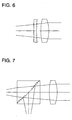
- the coupling lens optical system including a glass lens having negative refracting power it is possible, in the coupling lens optical system including a glass lens having negative refracting power, to make at least one optical surface thereof to be a zonal diffraction surface having negative diffraction power, and it is possible to realize a coupling optical system wherein a zonal diffraction surface having negative diffraction power is provided on a surface on one side of a parallel plane board or on a slanting surface of a beam splitter as shown in Figs. 6 and 7.
- the parallel plane board or a beam splitter on which a zonal diffraction surface is provided are also included in the coupling optical system.
- a lens optical system has two or more lenses having positive refracting power. It is the same also in the optical system with NA of 0.8 or more, and even in the case where one or two out of two lenses having positive refracting power are made to be a resin-made lens, it is possible, by using the invention, to structure an optical system for recording on and reproducing from an optical information recording medium having sufficient efficiency at low cost for ambient temperature fluctuation, without making an optical system to be large.
- An apparatus for recording and/or reproducing an optical information recording medium of the invention for recording/reproducing an optical information recording medium has therein an optical pickup apparatus of the invention, and it further has preferably a spindle motor.
- a coupling lens of the invention is a resin-made lens having positive refracting power, and a zonal diffraction portion having negative diffraction power is provided on at least one side of the resin-made lens.
- the following conditional expression is satisfied; 0.12 ⁇ dr/f ⁇ 1.2 wherein, dr represents a diameter of the aforesaid zonal diffraction portion and f represents a focal length.
- the coupling lens may also be a collimator lens.
- Fig. 3 shows results of the simulation of changes in wavefront aberration caused by temperature fluctuation which was made after designing a light-converging optical system based on the invention.
- Fig. 3 shows a graph wherein the axis of ordinates represents variation amount of component of spherical aberration in wavefront aberration ⁇ Wt in this optical system, the axis of abscissas represents power ⁇ cr caused by refraction, and temperature difference is made to be 30°C.
- curve A in the graph shows a simulation value in the occasion wherein the wavelength of a light source is 635 nm and it remains unchanged even when temperature rises
- the temperature-dependency of oscillation wavelength of a semiconductor laser is considered, the temperature-dependency of the wavefront aberration is further made to be smaller.
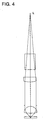
- FIG. 4 Structure of the optical system in Example 1 is as shown in Fig. 4 wherein focal length fr caused by refraction of a collimator is 15 mm.
- the optical system in Example 2 is shown in Fig. 5 wherein focal length fr caused by refraction of a collimator is 10 mm.
- a cover glass a coupling lens (collimator lens), a diaphragm, an objective lens and a transparent base board of an optical information recording medium in this order from light source L.
- a zonal diffraction surface is provided on the side of the coupling lens (collimator lens) closer to the objective lens.
- ri represents a radius of curvature of a refraction surface
- di represents a distance between surfaces
- ni shows a refractive index at a primary wavelength.
- a diffraction surface is expressed by the following expression where the unit is in mm, as a function of optical path difference.
- locations on an optical axis and in the vicinity of the optical axis do not necessarily need to be provided with a zonal diffraction surface, because the depth on these locations is great. It is preferable that an area of the zonal diffraction surface is 70% or more of the total area of the optical surface.
- an optical pickup apparatus and its optical system of the invention in an optical system employing a resin-made objective lens and a coupling optical system, it has become possible to realize an inexpensive optical system capable of keeping its sufficient capacity for fluctuation of ambient temperature used, through the simple structure to provide a zonal diffraction surface having negative diffraction power in a resin-made optical system included in the coupling optical system.
Landscapes
- Physics & Mathematics (AREA)
- Optics & Photonics (AREA)
- General Physics & Mathematics (AREA)
- Optical Head (AREA)
- Lenses (AREA)
- Diffracting Gratings Or Hologram Optical Elements (AREA)
Applications Claiming Priority (2)
| Application Number | Priority Date | Filing Date | Title |
|---|---|---|---|
| JP19525799A JP4288769B2 (ja) | 1999-07-09 | 1999-07-09 | 光情報記録媒体の記録および/または再生用集光光学系および光ピックアップ装置 |
| JP19525799 | 1999-07-09 |
Publications (2)
| Publication Number | Publication Date |
|---|---|
| EP1067530A2 true EP1067530A2 (de) | 2001-01-10 |
| EP1067530A3 EP1067530A3 (de) | 2006-02-01 |
Family
ID=16338138
Family Applications (1)
| Application Number | Title | Priority Date | Filing Date |
|---|---|---|---|
| EP00114312A Withdrawn EP1067530A3 (de) | 1999-07-09 | 2000-07-04 | Optische Aufzeichnungs/Wiedergabevorrichtung, optisches System dafür und Koppellinse |
Country Status (5)
| Country | Link |
|---|---|
| EP (1) | EP1067530A3 (de) |
| JP (1) | JP4288769B2 (de) |
| KR (1) | KR20010049748A (de) |
| CN (1) | CN1147845C (de) |
| TW (1) | TW451077B (de) |
Cited By (4)
| Publication number | Priority date | Publication date | Assignee | Title |
|---|---|---|---|---|
| EP1329881A2 (de) * | 2002-01-22 | 2003-07-23 | Konica Corporation | Lichtkonvergierendes optisches System, optisches Abtastgerät, Aberrationskorrekturelement und Objektivlinse |
| EP1359574A3 (de) * | 2002-04-26 | 2006-11-15 | Konica Minolta Opto, Inc. | Optisches Aufzeichnungs- und Wiedergabesystem, Objektivlinse und optisches Element zur Aberrationskorrektur |
| SG127721A1 (en) * | 2003-04-15 | 2006-12-29 | Konica Minolta Opto Inc | Optical pickup device, optical information recording and reproducing apparatus and objective lens |
| EP2254115A3 (de) * | 2009-05-21 | 2011-01-05 | Funai Electric Co., Ltd. | Optisches Plattengerät |
Families Citing this family (5)
| Publication number | Priority date | Publication date | Assignee | Title |
|---|---|---|---|---|
| JP2002367213A (ja) * | 2001-06-06 | 2002-12-20 | Konica Corp | 光ピックアップ装置の光学素子 |
| CN101128874B (zh) * | 2005-02-25 | 2012-09-26 | 松下电器产业株式会社 | 光学拾取装置及其中所使用的物方光学系统 |
| JP2007242115A (ja) | 2006-03-07 | 2007-09-20 | Konica Minolta Opto Inc | 光ピックアップ装置 |
| CN101405800B (zh) * | 2006-03-20 | 2011-04-13 | 松下电器产业株式会社 | 光学头及光盘装置 |
| US9904068B1 (en) * | 2017-01-09 | 2018-02-27 | Asml Netherlands B.V. | Reducing an optical power of a reflected light beam |
Citations (4)
| Publication number | Priority date | Publication date | Assignee | Title |
|---|---|---|---|---|
| US5475537A (en) * | 1993-03-05 | 1995-12-12 | Konica Corporation | Optical system for use in recording and reading information on an optical information medium |
| JPH09115173A (ja) * | 1995-10-17 | 1997-05-02 | Sankyo Seiki Mfg Co Ltd | 光ヘッド装置 |
| EP0776004A2 (de) * | 1995-11-02 | 1997-05-28 | Konica Corporation | Optisches System zur Aufzeichnung und Wiedergabe eines optischen Informationsaufzeichnungsmediums |
| WO1998019303A1 (fr) * | 1996-10-31 | 1998-05-07 | Sanyo Electric Co., Ltd. | Dispositif de lecture optique |
-
1999
- 1999-07-09 JP JP19525799A patent/JP4288769B2/ja not_active Expired - Fee Related
-
2000
- 2000-06-29 TW TW089112906A patent/TW451077B/zh not_active IP Right Cessation
- 2000-07-04 EP EP00114312A patent/EP1067530A3/de not_active Withdrawn
- 2000-07-07 CN CNB001204203A patent/CN1147845C/zh not_active Expired - Fee Related
- 2000-07-08 KR KR1020000039119A patent/KR20010049748A/ko not_active Application Discontinuation
Patent Citations (4)
| Publication number | Priority date | Publication date | Assignee | Title |
|---|---|---|---|---|
| US5475537A (en) * | 1993-03-05 | 1995-12-12 | Konica Corporation | Optical system for use in recording and reading information on an optical information medium |
| JPH09115173A (ja) * | 1995-10-17 | 1997-05-02 | Sankyo Seiki Mfg Co Ltd | 光ヘッド装置 |
| EP0776004A2 (de) * | 1995-11-02 | 1997-05-28 | Konica Corporation | Optisches System zur Aufzeichnung und Wiedergabe eines optischen Informationsaufzeichnungsmediums |
| WO1998019303A1 (fr) * | 1996-10-31 | 1998-05-07 | Sanyo Electric Co., Ltd. | Dispositif de lecture optique |
Non-Patent Citations (1)
| Title |
|---|
| PATENT ABSTRACTS OF JAPAN vol. 1997, no. 09, 30 September 1997 (1997-09-30) -& JP 09 115173 A (SANKYO SEIKI MFG CO LTD), 2 May 1997 (1997-05-02) * |
Cited By (8)
| Publication number | Priority date | Publication date | Assignee | Title |
|---|---|---|---|---|
| EP1329881A2 (de) * | 2002-01-22 | 2003-07-23 | Konica Corporation | Lichtkonvergierendes optisches System, optisches Abtastgerät, Aberrationskorrekturelement und Objektivlinse |
| EP1329881A3 (de) * | 2002-01-22 | 2006-11-02 | Konica Corporation | Lichtkonvergierendes optisches System, optisches Abtastgerät, Aberrationskorrekturelement und Objektivlinse |
| EP1359574A3 (de) * | 2002-04-26 | 2006-11-15 | Konica Minolta Opto, Inc. | Optisches Aufzeichnungs- und Wiedergabesystem, Objektivlinse und optisches Element zur Aberrationskorrektur |
| US7327663B2 (en) | 2002-04-26 | 2008-02-05 | Konica Corporation | Recording reproducing optical system, objective lens, and aberration correcting optical element |
| SG127721A1 (en) * | 2003-04-15 | 2006-12-29 | Konica Minolta Opto Inc | Optical pickup device, optical information recording and reproducing apparatus and objective lens |
| US7253968B2 (en) | 2003-04-15 | 2007-08-07 | Konica Minolta Opto, Inc. | Optical pickup device, optical information recording and reproducing apparatus and objective lens |
| EP2254115A3 (de) * | 2009-05-21 | 2011-01-05 | Funai Electric Co., Ltd. | Optisches Plattengerät |
| US8264923B2 (en) | 2009-05-21 | 2012-09-11 | Funai Electric Co., Ltd. | Optical disc device |
Also Published As
| Publication number | Publication date |
|---|---|
| EP1067530A3 (de) | 2006-02-01 |
| KR20010049748A (ko) | 2001-06-15 |
| JP2001023228A (ja) | 2001-01-26 |
| TW451077B (en) | 2001-08-21 |
| CN1147845C (zh) | 2004-04-28 |
| CN1280363A (zh) | 2001-01-17 |
| JP4288769B2 (ja) | 2009-07-01 |
Similar Documents
| Publication | Publication Date | Title |
|---|---|---|
| KR101002543B1 (ko) | 광 픽업 장치 | |
| US6865025B2 (en) | Aberration compensating optical element, optical system, optical pickup device, recorder and reproducer | |
| EP1199717A2 (de) | Objektivlinse, Koppellinse, lichtkonvergierendes optisches System, und optisches Abtastgerät | |
| EP1081692A2 (de) | Objektivlinse für Abtastgerät und optisches Abtastgerät | |
| EP1304689A2 (de) | Objektivlinse, Objektivelement, Objektivabtastgerät, und damit augerüstetes optisches Informationsaufzeichnungs- und/oder -Wiedergabegerät | |
| US7924683B2 (en) | Optical pickup apparatus with objective optical system and guiding optical system | |
| EP1610313B1 (de) | Konvergierendes optisches Element und optisches Abtastgerät | |
| CN101789243B (zh) | 物镜、光拾取装置及光信息记录再生装置 | |
| KR100765741B1 (ko) | 일 매의 렌즈로 된 고개구수의 대물렌즈 및 이를 채용한광픽업장치 | |
| KR20050048649A (ko) | 광학 요소, 대물 광학 요소 및 광학 픽업 장치 | |
| US6411587B1 (en) | Optical pickup optical system, optical pickup apparatus, coupling optical system, coupling optical system lens and recording/reproduction apparatus | |
| EP1067530A2 (de) | Optische Aufzeichnungs/Wiedergabevorrichtung, optisches System dafür und Koppellinse | |
| EP1205926A2 (de) | Objektivlinse und optisches Abtastgerät | |
| EP1416480A2 (de) | Objektivelement und optisches Abstastgerät | |
| US20070253310A1 (en) | Coupling Lens and Optical Pickup Apparatus | |
| US7440382B2 (en) | Objective optical element with multiple diffractive surfaces and optical pickup device | |
| JP2001194581A (ja) | 対物レンズ及び光ピックアップ装置 | |
| US20040047040A1 (en) | Objective lens and optical pickup device | |
| JP4294460B2 (ja) | 対物レンズ,光ピックアップ装置及び光ディスク装置 | |
| JP2002203331A (ja) | 光ピックアップ装置及び対物レンズ | |
| JP2006244656A (ja) | 対物レンズ、光ピックアップ装置、及び光ディスク装置 | |
| JP4397471B2 (ja) | 光学ヘッド | |
| JP4329329B2 (ja) | 光学素子及び光ピックアップ装置 | |
| JP2009104774A (ja) | 光学素子、対物光学素子及び光ピックアップ装置 | |
| JPWO2006090653A1 (ja) | 光ピックアップ装置、それに用いる対物光学系 |
Legal Events
| Date | Code | Title | Description |
|---|---|---|---|
| PUAI | Public reference made under article 153(3) epc to a published international application that has entered the european phase |
Free format text: ORIGINAL CODE: 0009012 |
|
| AK | Designated contracting states |
Kind code of ref document: A2 Designated state(s): AT BE CH CY DE DK ES FI FR GB GR IE IT LI LU MC NL PT SE |
|
| AX | Request for extension of the european patent |
Free format text: AL;LT;LV;MK;RO;SI |
|
| PUAL | Search report despatched |
Free format text: ORIGINAL CODE: 0009013 |
|
| AK | Designated contracting states |
Kind code of ref document: A3 Designated state(s): AT BE CH CY DE DK ES FI FR GB GR IE IT LI LU MC NL PT SE |
|
| AX | Request for extension of the european patent |
Extension state: AL LT LV MK RO SI |
|
| AKX | Designation fees paid | ||
| STAA | Information on the status of an ep patent application or granted ep patent |
Free format text: STATUS: THE APPLICATION IS DEEMED TO BE WITHDRAWN |
|
| 18D | Application deemed to be withdrawn |
Effective date: 20070201 |
|
| REG | Reference to a national code |
Ref country code: DE Ref legal event code: 8566 |