EP1067394A2 - Teilabgeschirmte Gradientenspulenanordnung für ein Gerät der bildgebenden magnetischen Resonanz - Google Patents
Teilabgeschirmte Gradientenspulenanordnung für ein Gerät der bildgebenden magnetischen Resonanz Download PDFInfo
- Publication number
- EP1067394A2 EP1067394A2 EP00305132A EP00305132A EP1067394A2 EP 1067394 A2 EP1067394 A2 EP 1067394A2 EP 00305132 A EP00305132 A EP 00305132A EP 00305132 A EP00305132 A EP 00305132A EP 1067394 A2 EP1067394 A2 EP 1067394A2
- Authority
- EP
- European Patent Office
- Prior art keywords
- coil
- gradient coil
- windings
- partially shielding
- winding density
- Prior art date
- Legal status (The legal status is an assumption and is not a legal conclusion. Google has not performed a legal analysis and makes no representation as to the accuracy of the status listed.)
- Ceased
Links
Images


Classifications
-
- A—HUMAN NECESSITIES
- A61—MEDICAL OR VETERINARY SCIENCE; HYGIENE
- A61B—DIAGNOSIS; SURGERY; IDENTIFICATION
- A61B5/00—Measuring for diagnostic purposes; Identification of persons
- A61B5/05—Detecting, measuring or recording for diagnosis by means of electric currents or magnetic fields; Measuring using microwaves or radio waves
- A61B5/055—Detecting, measuring or recording for diagnosis by means of electric currents or magnetic fields; Measuring using microwaves or radio waves involving electronic [EMR] or nuclear [NMR] magnetic resonance, e.g. magnetic resonance imaging
-
- G—PHYSICS
- G01—MEASURING; TESTING
- G01R—MEASURING ELECTRIC VARIABLES; MEASURING MAGNETIC VARIABLES
- G01R33/00—Arrangements or instruments for measuring magnetic variables
- G01R33/20—Arrangements or instruments for measuring magnetic variables involving magnetic resonance
- G01R33/28—Details of apparatus provided for in groups G01R33/44 - G01R33/64
- G01R33/42—Screening
- G01R33/421—Screening of main or gradient magnetic field
- G01R33/4215—Screening of main or gradient magnetic field of the gradient magnetic field, e.g. using passive or active shielding of the gradient magnetic field
Definitions
- the present invention relates to a gradient coil for an MRI (magnetic resonance imaging) apparatus, a method of manufacturing a gradient coil for an MRI apparatus, and an MRI apparatus, and more particularly to a gradient coil for an MRI apparatus having a low electric power loss and a low heat release in its shielding coil, a method of manufacturing such a gradient coil, and an MRI apparatus.
- MRI magnetic resonance imaging
- Figure 11 illustrates an exemplary magnet assembly in a conventional MRI apparatus.
- the magnet assembly 51 comprises yokes 20, a pair of opposing permanent magnets 1Mt and 1Mb attached to the yokes 20 for generating a static magnetic field, magnetic field conditioning plates 24 and 25 disposed on the opposing surfaces of the permanent magnets 1Mt and 1Mb, respectively, for improving homogeneity of the static magnetic field, upper and lower Z-axis main gradient coils 1Zt and 1Zb disposed on the opposing surfaces of the magnetic field conditioning plates 24 and 25, respectively, for generating a Z-axis gradient magnetic field, an upper Z-axis shielding coil 51Zts for preventing magnetic flux generated by the upper Z-axis main gradient coil 1Zt from affecting the magnetic field conditioning plate 24, and a lower Z-axis shielding coil 51Zbs for preventing magnetic flux generated by the lower Z-axis main gradient coil 1Zb from affecting the magnetic field conditioning plate 25.
- a combination of the upper Z-axis shielding coil 51Zts, the upper Z-axis main gradient coil 1Zt, the lower Z-axis main gradient coil 1Zb and the lower Z-axis shielding coil 51Zbs constitutes a Z-axis gradient coil 51Z.
- X- and Y-axis gradient coils are also disposed on the opposing surfaces of the magnetic field conditioning plates 24 and 25.
- Figure 12 is a schematic perspective view of the Z-axis gradient coil 51Z.
- Windings of the upper Z-axis shielding coil 51Zts are disposed corresponding to the entire winding area of the upper Z-axis main gradient coil 1Zt. However, the number of the windings of the upper Z-axis shielding coil 51Zts is less than that of the upper Z-axis main gradient coil 1Zt.
- the number of windings of the conventional Z-axis shielding coils 51Zts and 51Zbs is less than that of the Z-axis main gradient coils 1Zt and 1Zb, it is significantly large because the windings of the Z-axis shielding coils 51Zts and 51Zbs are positioned corresponding to the entire winding area of the Z-axis main gradient coils 1Zt and 1Zb.
- the Z-axis shielding coils 51Zts and 51Zbs have a large electric power loss.
- the conventional gradient coil for the MRI apparatus gives rise to a problem of generating a large electric power loss, and hence a large heat release in its shielding coil.
- a gradient coil for an MRI apparatus comprising a partially shielding coil interposed between a main gradient coil and a magnetic component, the partially shielding coil having its windings positioned only in a high winding density zone containing a portion in which a winding density of the main gradient coil is highest.
- the windings of the shielding coil are positioned corresponding only to a high winding density zone, rather than corresponding to the entire winding area, of the main gradient coil. (For this reason, the coil is called a "partially shielding coil".) Accordingly, the number of the windings can be reduced, thereby reducing the electric power loss and the heat release. In addition, since the shielding performance required can still be attained, magnetic flux generated by the main gradient coil can be prevented from affecting a magnetic component (such as a magnetic field conditioning plate), thereby avoiding an adverse effect of remanence in the magnetic component.
- a magnetic component such as a magnetic field conditioning plate
- a method of manufacturing a gradient coil for an MRI apparatus comprising the steps of applying an image electric current method only to a high winding density zone containing a portion in which a winding density of a main gradient coil is highest and applying a boundary condition only to the same zone to determine the position of windings of a partially shielding coil having its windings positioned only in the high winding density zone.
- the image electric current method is applied only to a high winding density zone and the boundary condition is applied only to the same zone, rather than to the entire winding area of the main gradient coil. Accordingly, the windings of the shielding coil can be suitably positioned corresponding only to the high winding density zone. (For this reason, the coil is called a "partially shielding coil”.)
- a method of manufacturing a gradient coil for an MRI apparatus comprising the steps of defining an optimization plane between a partially shielding coil and a magnetic component lying near the partially shielding coil, the partially shielding coil having its windings positioned only in a high winding density zone containing a portion in which a winding density of a main gradient coil is highest, and optimizing the position of the windings of the partially shielding coil by a least squares technique so that a magnetic field is minimized within the optimization plane.
- the windings of the shielding coil are positioned only in a high winding density zone, rather than over the entire winding area, of the main gradient coil, and the position of the windings is optimized by a least squares technique. Accordingly, the windings of the shielding coil can be suitably positioned corresponding only to the high winding density zone. (For this reason, the coil is called a "partially shielding coil”.)
- a method of manufacturing a gradient coil for an MRI apparatus comprising the steps of applying an image electric current method only to a high winding density zone containing a portion in which a winding density of a main gradient coil is highest and applying a boundary condition only to the same zone to determine the position of windings of a partially shielding coil having its windings positioned only in the high winding density zone, and then defining an optimization plane between the partially shielding coil and a magnetic component lying near the partially shielding coil, and optimizing the position of the windings of the partially shielding coil by a least squares technique so that a magnetic field is minimized within the optimization plane.
- the image electric current method is applied only to a high winding density zone and the boundary condition is applied only to the same zone, rather than to the entire winding area of the main gradient coil. Accordingly, the windings of the shielding coil can be suitably positioned corresponding only to the high winding density zone. (For this reason, the coil is called a "partially shielding coil".) Moreover, the position of the windings of the partially shielding coil is optimized by a least squares technique. Accordingly, the windings of the shielding coil can be more suitably positioned.
- an MRI apparatus comprising a gradient coil including a main gradient coil, and a partially shielding coil having its windings positioned only in a high winding density zone containing a portion in which a winding density of the main gradient coil is highest.
- the windings of the shielding coil are positioned corresponding only to a high winding density zone, rather than corresponding to the entire winding area of the main gradient coil. (For this reason, the coil is called a "partially shielding coil".) Accordingly, the number of windings of the shielding coil can be reduced, thereby reducing the electric power loss and the heat release. In addition, since the shielding performance required can still be attained, magnetic flux generated by the main gradient coil can be prevented from affecting a magnetic component (such as a magnetic field conditioning plate), thereby avoiding image quality degradation due to an adverse effect of remanence in the magnetic component.
- a magnetic component such as a magnetic field conditioning plate
- the method of manufacturing a gradient coil for an MRI apparatus and the MRI apparatus of the present invention the number of windings of the shielding coil can be reduced, thereby reducing the electric power loss and the heat release.
- the shielding performance required can still be attained, magnetic flux generated by the main gradient coil can be prevented from affecting a magnetic component, thereby avoiding image quality degradation due to an adverse effect of remanence in the magnetic component.
- Figure 1 is a configuration block diagram showing an MRI apparatus in accordance with an embodiment of the present invention.
- a magnet assembly 1 has therein a bore (vacant portion) into which a subject is inserted, and surrounding the bore, the magnet assembly 1 comprises an X-axis gradient coil 1X for generating an X-axis gradient magnetic field, a Y-axis gradient coil 1Y for generating a Y-axis gradient magnetic field, a Z-axis gradient coil 1Z for generating a Z-axis gradient magnetic field, a transmit coil 1T for applying RF pulses to excite spins of atomic nuclei within the subject, a receive coil 1R for detecting NMR signals from the subject, and a permanent magnet pair 1M for generating a static magnetic field.
- X-axis gradient coil 1X for generating an X-axis gradient magnetic field
- a Y-axis gradient coil 1Y for generating a Y-axis gradient magnetic field
- a Z-axis gradient coil 1Z for generating a Z-axis gradient magnetic field
- a transmit coil 1T for applying RF pulses to
- a superconductive magnet may be used instead of the permanent magnet pair 1M.
- the X-axis gradient coil 1X is connected to an X-axis gradient coil driving circuit 3X.
- the Y-axis gradient coil 1Y is connected to a Y-axis gradient coil driving circuit 3Y.
- the Z-axis gradient coil 1Z is connected to a Z-axis gradient coil driving circuit 3Z.
- the transmit coil 1T is connected to an RF power amplifier 4.
- the receive coil 1R is connected to a preamplifier 5.
- a sequence memory circuit 8 operates the X-, Y- and Z- gradient coil driving circuits 3X, 3Y and 3Z according to instructions from a computer 7 based on a pulse sequence of a spin-echo technique or the like, to generate an X-axis gradient magnetic field, Y-axis gradient magnetic field and Z-axis gradient magnetic field from the X-, Y- and Z-axis gradient coils 1X, 1Y and 1Z, respectively.
- the sequence memory circuit 8 also operates a gate modulation circuit 9 to modulate a high frequency output signal from an RF oscillating circuit 10 into a pulsed signal having a predetermined timing and a predetermined envelope, and applies the pulsed signal to the RF power amplifier 4 as an excitation pulse. After power-amplified in the RF power amplifier 4, the signal is applied to the transmit coil 1T in the magnet assembly 1 to selectively excite a desired slice region.
- the preamplifier 5 amplifies an NMR signal from the subject detected by the receive coil 1R in the magnet assembly 1, and inputs the signal into a phase detector 12.
- the phase detector 12 phase-detects the NMR signal from the preamplifier 5 with the output from the RF oscillating circuit 10 as a reference signal, and supplies the phase-detected signal to an A/D converter 11.
- the A/D converter 11 converts the phase-detected analog signal to digital MR signal data, and inputs it to the computer 7.
- the computer 7 performs an image reconstruction calculation on the MR data to produce an image of the desired slice region.
- the image is displayed on a display device 6.
- the computer 7 is also responsible for overall control such as accepting information input from an operator console 13.
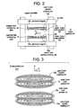
- Figure 2 is a schematic view illustrating the main portion (which relates to the present invention) of the magnet assembly 1.
- the magnet assembly 1 comprises yokes 20, a pair of opposing permanent magnets 1Mt and 1Mb attached to the yokes 20 for generating a static magnetic field, magnetic field conditioning plates 24 and 25 disposed on the opposing surfaces of the permanent magnets 1Mt and 1Mb, respectively, for improving homogeneity of the static magnetic field, upper and lower Z-axis main gradient coils 1Zt and 1Zb disposed on the opposing surfaces of the magnetic field conditioning plates 24 and 25, respectively, for generating a Z-axis gradient magnetic field, an upper Z-axis partially shielding coil 1Zts for preventing magnetic flux generated by the upper Z-axis main gradient coil 1Zt from affecting the magnetic field conditioning plate 24, and a lower Z-axis partially shielding coil 1Zbs for preventing magnetic flux generated by the lower Z-axis main gradient coil 1Zb from affecting the magnetic field conditioning plate 25.
- a combination of the upper Z-axis partially shielding coil 1Zts, the upper Z-axis main gradient coil 1Zt, the lower Z-axis main gradient coil 1Zb and the lower Z-axis partially shielding coil 1Zbs constitutes a Z-axis gradient coil 1Z.
- the X- and Y-axis gradient coils 1X and 1Y are also disposed on the opposing surfaces of the magnetic field conditioning plates 24 and 25.
- Figure 3 is a schematic perspective view of the Z-axis gradient coil 1Z.
- the windings of the upper Z-axis partially shielding coil 1Zts are positioned only in a high winding density zone (designated as 1Zp in Fig. 4) containing a portion in which a winding density of the upper Z-axis main gradient coil 1Zt is highest, rather than positioned corresponding to the entire winding area of the upper Z-axis main gradient coil 1Zt.
- Figure 4 is a schematic cross-sectional view of the Z-axis gradient coil 1Z.
- a surface magnetic flux density distribution profile Sm represents the distribution of magnetic flux density on the surface of each of the magnetic field conditioning plates 24 and 25.
- Another surface magnetic flux density distribution profile Sm' is shown in Fig. 7 in the absence of the Z-axis partially shielding coils 1Zts and 1Zbs. As can be seen by comparing these profiles, the magnetic flux density is suppressed on the surfaces of the magnetic field conditioning plates 24 and 25 by the presence of the Z-axis partially shielding coils 1Zts and 1Zbs. Thus, an adverse effect of remanence in the magnetic field conditioning plates 24 and 25 can be avoided.
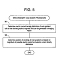
- Figure 5 is a flow chart showing a procedure of designing a main gradient coil for manufacturing the main gradient coils 1Zt and 1Zb.
- Step M1 an electric current density distribution of the main gradient coil is determined so that a desired gradient magnetic field can be generated in an imaging region.
- Step M2 the position of the windings of the main gradient coil is determined based on the magnitude of electric current which the main gradient coil can carry and the electric current density distribution obtained at Step M1.
- Figure 6 is a flow chart showing a procedure of designing a partially shielding coil for manufacturing the Z-axis partially shielding coils 1Zts and 1Zbs.
- Step S1 the surface magnetic flux density distribution profile Sm' is calculated when gradient electric current I flows through the main gradient coil 1Zb in the absence of the Z-axis partially shielding coil 1Zbs, as shown in Fig. 7.
- a zone having a magnetic flux density of greater than 30 %, for example, of the peak of the surface magnetic flux density distribution profile Sm' is then defined as a high winding density zone 1Zp.
- the high winding density zone 1Zp can also be called a high magnetic flux density zone.
- an electric current density distribution of the partially shielding coil is determined by applying an image electric current method only to the high winding density zone 1Zp, and applying a boundary condition only to the same zone, as shown in Fig. 8.
- a boundary K is assumed at the height of the partially shielding coil, and image electric current Ii flowing in the direction opposite to gradient electric current I is assumed at a mirror position of the gradient electric current I with respect to the boundary K. Then, a magnetic field distribution is calculated at the boundary K, and the resulting magnetic field distribution is employed as an electric current density distribution.
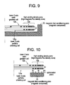
- Step S2 the position of windings of the partially shielding coil is determined, as shown in Fig. 9, based on the magnitude of the electric current which the partially shielding coil can carry, and the electric current density distribution obtained at Step S1.
- the optimum position of the windings can be determined for the Z-axis partially shielding coil 1Zts and 1Zbs as shown in Fig. 4.
- the optimization plane P is defined at a position about 1 mm apart from the magnetic component, for example. Moreover, while a sufficiently large number of evaluation points may be defined at regular intervals, it is preferred that a minimum number of evaluation points be defined in a density distribution such that the magnetic field distribution can be appropriately sampled in the optimization plane P, in order to reduce a load to the calculation process.
- the partially shielding coils 1Zts and 1Zbs are employed having their windings positioned corresponding only to the high winding density zone 1Zp, rather than corresponding to the entire winding area, of the main gradient coils 1Zt and 1Zb, the number of windings of the shielding coils can be reduced, thereby reducing the electric power loss and the heat release.
- the shielding performance required can still be attained, magnetic flux generated by the main gradient coils 1Zt and 1Zb can be prevented from affecting the magnetic field conditioning plates 24 and 25 and the like, thereby avoiding image degradation due to an adverse effect of remanence in the magnetic field conditioning plates 24 and 25 and the like.
Landscapes
- Health & Medical Sciences (AREA)
- Physics & Mathematics (AREA)
- Life Sciences & Earth Sciences (AREA)
- Epidemiology (AREA)
- Condensed Matter Physics & Semiconductors (AREA)
- General Physics & Mathematics (AREA)
- Nuclear Medicine, Radiotherapy & Molecular Imaging (AREA)
- Pathology (AREA)
- Medical Informatics (AREA)
- Biophysics (AREA)
- High Energy & Nuclear Physics (AREA)
- Engineering & Computer Science (AREA)
- Biomedical Technology (AREA)
- Heart & Thoracic Surgery (AREA)
- Radiology & Medical Imaging (AREA)
- Molecular Biology (AREA)
- Surgery (AREA)
- Animal Behavior & Ethology (AREA)
- General Health & Medical Sciences (AREA)
- Public Health (AREA)
- Veterinary Medicine (AREA)
- Magnetic Resonance Imaging Apparatus (AREA)
Applications Claiming Priority (2)
| Application Number | Priority Date | Filing Date | Title |
|---|---|---|---|
| JP17236899A JP3209982B2 (ja) | 1999-06-18 | 1999-06-18 | Mri装置用勾配コイル、mri装置用勾配コイルの製造方法およびmri装置 |
| JP17236899 | 1999-06-18 |
Publications (2)
| Publication Number | Publication Date |
|---|---|
| EP1067394A2 true EP1067394A2 (de) | 2001-01-10 |
| EP1067394A3 EP1067394A3 (de) | 2002-04-24 |
Family
ID=15940620
Family Applications (1)
| Application Number | Title | Priority Date | Filing Date |
|---|---|---|---|
| EP00305132A Ceased EP1067394A3 (de) | 1999-06-18 | 2000-06-16 | Teilabgeschirmte Gradientenspulenanordnung für ein Gerät der bildgebenden magnetischen Resonanz |
Country Status (5)
| Country | Link |
|---|---|
| US (1) | US6362623B1 (de) |
| EP (1) | EP1067394A3 (de) |
| JP (1) | JP3209982B2 (de) |
| KR (1) | KR100398560B1 (de) |
| CN (1) | CN1231178C (de) |
Families Citing this family (16)
| Publication number | Priority date | Publication date | Assignee | Title |
|---|---|---|---|---|
| JP3987686B2 (ja) * | 2001-02-02 | 2007-10-10 | ジーイー・メディカル・システムズ・グローバル・テクノロジー・カンパニー・エルエルシー | 静磁界補正方法およびmri装置 |
| JP3878434B2 (ja) * | 2001-05-10 | 2007-02-07 | ジーイー・メディカル・システムズ・グローバル・テクノロジー・カンパニー・エルエルシー | 磁気共鳴撮像用コイル構造体および磁気共鳴撮像装置 |
| JP3884243B2 (ja) * | 2001-06-21 | 2007-02-21 | ジーイー・メディカル・システムズ・グローバル・テクノロジー・カンパニー・エルエルシー | 外部磁界測定方法、静磁界補正方法、外部磁界測定装置およびmri装置 |
| JP3845048B2 (ja) * | 2002-08-27 | 2006-11-15 | ジーイー・メディカル・システムズ・グローバル・テクノロジー・カンパニー・エルエルシー | 磁気共鳴撮影装置 |
| US6657432B1 (en) * | 2002-09-25 | 2003-12-02 | Fonar Corporation | Gradient coils for MRI systems having multiple current density zones |
| US6850066B2 (en) | 2003-05-15 | 2005-02-01 | Ge Medical Systems Global Technology Company Llc | Systems and methods for gradient compensation in magnetic resonance imaging |
| JP2009520576A (ja) * | 2005-12-20 | 2009-05-28 | コーニンクレッカ フィリップス エレクトロニクス エヌ ヴィ | 長手方向磁場傾斜システムを有する磁気共鳴スキャナ |
| WO2010064155A1 (en) * | 2008-12-05 | 2010-06-10 | Koninklijke Philips Electronics, N.V. | Active device tracking using light with orbital angular momentum to induce a hyperpolarized mri |
| DE102012205292B4 (de) * | 2012-03-30 | 2013-12-12 | Siemens Aktiengesellschaft | Ansteuerung eines Magnetresonanzsystems |
| CN105044635A (zh) * | 2015-06-12 | 2015-11-11 | 北京斯派克科技发展有限公司 | 用于关节磁共振成像的梯度线圈 |
| CN107045112A (zh) * | 2016-02-09 | 2017-08-15 | 温伯格医学物理有限公司 | 操作用于磁共振成像和图像引导治疗的电永磁铁的方法和设备 |
| WO2017142838A1 (en) * | 2016-02-17 | 2017-08-24 | Weinberg Medical Physics, Inc. | Apparatus and method for rapid and comfortable magnetic imaging of breast tissues, with cultural sensitivity |
| CN107957565B (zh) * | 2017-12-21 | 2019-11-19 | 武汉中科牛津波谱技术有限公司 | 一种核磁共振波谱仪自屏蔽梯度线圈及其设计方法 |
| CN109946631B (zh) * | 2019-03-27 | 2021-06-25 | 中国计量大学 | 最小化最大温度值的盘式梯度线圈 |
| CN109946630B (zh) * | 2019-03-27 | 2021-05-28 | 中国计量大学 | 最小化最大温度值的盘式梯度线圈设计方法 |
| CN111044959A (zh) * | 2019-12-25 | 2020-04-21 | 上海联影医疗科技有限公司 | 磁共振线圈组件及具有该组件的磁共振成像设备 |
Citations (2)
| Publication number | Priority date | Publication date | Assignee | Title |
|---|---|---|---|---|
| US5581187A (en) * | 1994-06-29 | 1996-12-03 | Siemens Aktiengesellschaft | Actively shielded planar gradient coil for pole plate magnets of a magnetic resonance imaging apparatus |
| US5793209A (en) * | 1995-03-16 | 1998-08-11 | Kabushiki Kaisha Toshiba | Nuclear magnetic resonance imaging apparatus using asymmetric torque-free active shield gradient coils |
Family Cites Families (1)
| Publication number | Priority date | Publication date | Assignee | Title |
|---|---|---|---|---|
| JPS60210804A (ja) * | 1984-04-04 | 1985-10-23 | Hitachi Ltd | 永久磁石装置 |
-
1999
- 1999-06-18 JP JP17236899A patent/JP3209982B2/ja not_active Expired - Fee Related
-
2000
- 2000-04-10 US US09/546,222 patent/US6362623B1/en not_active Expired - Fee Related
- 2000-06-15 KR KR10-2000-0032875A patent/KR100398560B1/ko not_active IP Right Cessation
- 2000-06-16 EP EP00305132A patent/EP1067394A3/de not_active Ceased
- 2000-06-19 CN CNB001186434A patent/CN1231178C/zh not_active Expired - Fee Related
Patent Citations (2)
| Publication number | Priority date | Publication date | Assignee | Title |
|---|---|---|---|---|
| US5581187A (en) * | 1994-06-29 | 1996-12-03 | Siemens Aktiengesellschaft | Actively shielded planar gradient coil for pole plate magnets of a magnetic resonance imaging apparatus |
| US5793209A (en) * | 1995-03-16 | 1998-08-11 | Kabushiki Kaisha Toshiba | Nuclear magnetic resonance imaging apparatus using asymmetric torque-free active shield gradient coils |
Non-Patent Citations (2)
| Title |
|---|
| JIANMING JIN: "Electromagnetic Analysis and Design in Magnetic Resonance Imaging" 1998 , CRC PRESS , BOCA RATON XP002190690 Chapter 3.7 Shielded Gradient Coils, pages 108-113 * |
| SCHOENIGER J S ET AL: "THE DESIGN AND CONSTRUCTION OF A NMR MICROSCOPY PROBE" JOURNAL OF MAGNETIC RESONANCE. SERIES B, ACADEMIC PRESS, ORLANDO, FL, US, vol. 104, no. 2, 1 June 1994 (1994-06-01), pages 127-134, XP000544489 ISSN: 1064-1866 * |
Also Published As
| Publication number | Publication date |
|---|---|
| EP1067394A3 (de) | 2002-04-24 |
| KR20010066842A (ko) | 2001-07-11 |
| KR100398560B1 (ko) | 2003-09-19 |
| JP2001000412A (ja) | 2001-01-09 |
| JP3209982B2 (ja) | 2001-09-17 |
| CN1279928A (zh) | 2001-01-17 |
| CN1231178C (zh) | 2005-12-14 |
| US6362623B1 (en) | 2002-03-26 |
Similar Documents
| Publication | Publication Date | Title |
|---|---|---|
| EP1067394A2 (de) | Teilabgeschirmte Gradientenspulenanordnung für ein Gerät der bildgebenden magnetischen Resonanz | |
| US5600245A (en) | Inspection apparatus using magnetic resonance | |
| US6489765B2 (en) | Magnetic field variation measuring method and magnetic field variation compensating method for MRI apparatus, and MRI apparatus | |
| CN102680926B (zh) | 脉冲序列、确定翻转角的方法和调节发送器电压的方法 | |
| JP3283242B2 (ja) | 勾配コイルの製造方法、勾配コイルおよびmri装置 | |
| Schmitt | The gradient system | |
| US6696835B2 (en) | Second-order static magnetic field correcting method and MRI apparatus | |
| JP2002143124A (ja) | 磁気共鳴イメージング装置 | |
| EP0390086B1 (de) | Verfahren zur Bilderzeugung mit magnetischer Resonanz | |
| US6400152B1 (en) | Spiral trajectory calculations for MRI | |
| JPS60179645A (ja) | Nmr断層撮影装置 | |
| US5587658A (en) | Shimming method for NMR magnet using unshielded gradient systems | |
| EP0850422B1 (de) | Mr-gerät mit mitteln zur reduzierung der auswirkungen von begleitenden gradienten | |
| US6850066B2 (en) | Systems and methods for gradient compensation in magnetic resonance imaging | |
| JP4392941B2 (ja) | 磁気共鳴イメージング装置 | |
| JP3887082B2 (ja) | 磁気共鳴イメージング装置 | |
| JP3091203B2 (ja) | 磁気共鳴イメージング装置 | |
| JPH10262947A (ja) | 磁気共鳴検査装置 | |
| JP3492003B2 (ja) | 磁気共鳴イメージング装置用静磁場発生装置 | |
| JP2000342551A (ja) | Mri装置 | |
| JP4699729B2 (ja) | Mrスキャン方法およびmri装置 | |
| JPH05300896A (ja) | 磁気共鳴イメージング装置 | |
| US20070249926A1 (en) | Magnetic Field Gradients Adapted to Position of Region Being Imaged | |
| de Vos et al. | Segmented RF shield design to minimize eddy currents for low-field Halbach MRI systems | |
| JP2000189396A (ja) | 静磁場補正用シムコイル装置 |
Legal Events
| Date | Code | Title | Description |
|---|---|---|---|
| PUAI | Public reference made under article 153(3) epc to a published international application that has entered the european phase |
Free format text: ORIGINAL CODE: 0009012 |
|
| AK | Designated contracting states |
Kind code of ref document: A2 Designated state(s): AT BE CH CY DE DK ES FI FR GB GR IE IT LI LU MC NL PT SE Kind code of ref document: A2 Designated state(s): DE FR GB |
|
| AX | Request for extension of the european patent |
Free format text: AL;LT;LV;MK;RO;SI |
|
| PUAL | Search report despatched |
Free format text: ORIGINAL CODE: 0009013 |
|
| AK | Designated contracting states |
Kind code of ref document: A3 Designated state(s): AT BE CH CY DE DK ES FI FR GB GR IE IT LI LU MC NL PT SE |
|
| AX | Request for extension of the european patent |
Free format text: AL;LT;LV;MK;RO;SI |
|
| 17P | Request for examination filed |
Effective date: 20021024 |
|
| AKX | Designation fees paid |
Free format text: DE FR GB |
|
| 17Q | First examination report despatched |
Effective date: 20061011 |
|
| STAA | Information on the status of an ep patent application or granted ep patent |
Free format text: STATUS: THE APPLICATION HAS BEEN REFUSED |
|
| 18R | Application refused |
Effective date: 20070530 |