EP1066459B2 - Brennkraftmaschine mit fluidkühlsystem - Google Patents
Brennkraftmaschine mit fluidkühlsystem Download PDFInfo
- Publication number
- EP1066459B2 EP1066459B2 EP99906243A EP99906243A EP1066459B2 EP 1066459 B2 EP1066459 B2 EP 1066459B2 EP 99906243 A EP99906243 A EP 99906243A EP 99906243 A EP99906243 A EP 99906243A EP 1066459 B2 EP1066459 B2 EP 1066459B2
- Authority
- EP
- European Patent Office
- Prior art keywords
- fluid
- combustion engine
- internal combustion
- cylinder
- engine according
- Prior art date
- Legal status (The legal status is an assumption and is not a legal conclusion. Google has not performed a legal analysis and makes no representation as to the accuracy of the status listed.)
- Expired - Lifetime
Links
- 239000012530 fluid Substances 0.000 title claims abstract description 59
- 238000002485 combustion reaction Methods 0.000 title claims abstract description 28
- 238000001816 cooling Methods 0.000 title claims abstract description 20
- XLYOFNOQVPJJNP-UHFFFAOYSA-N water Substances O XLYOFNOQVPJJNP-UHFFFAOYSA-N 0.000 claims abstract description 21
- 239000000498 cooling water Substances 0.000 description 17
- 239000002826 coolant Substances 0.000 description 6
- 239000012809 cooling fluid Substances 0.000 description 3
- 239000002689 soil Substances 0.000 description 3
- 239000000110 cooling liquid Substances 0.000 description 2
- 125000004122 cyclic group Chemical group 0.000 description 2
- 230000001419 dependent effect Effects 0.000 description 2
- 239000013598 vector Substances 0.000 description 2
- 230000015572 biosynthetic process Effects 0.000 description 1
- 238000010276 construction Methods 0.000 description 1
- 230000003247 decreasing effect Effects 0.000 description 1
- 230000001771 impaired effect Effects 0.000 description 1
- 239000007788 liquid Substances 0.000 description 1
- 238000004519 manufacturing process Methods 0.000 description 1
- 239000000463 material Substances 0.000 description 1
- 230000021715 photosynthesis, light harvesting Effects 0.000 description 1
Images
Classifications
-
- F—MECHANICAL ENGINEERING; LIGHTING; HEATING; WEAPONS; BLASTING
- F02—COMBUSTION ENGINES; HOT-GAS OR COMBUSTION-PRODUCT ENGINE PLANTS
- F02F—CYLINDERS, PISTONS OR CASINGS, FOR COMBUSTION ENGINES; ARRANGEMENTS OF SEALINGS IN COMBUSTION ENGINES
- F02F7/00—Casings, e.g. crankcases
- F02F7/0065—Shape of casings for other machine parts and purposes, e.g. utilisation purposes, safety
- F02F7/007—Adaptations for cooling
-
- F—MECHANICAL ENGINEERING; LIGHTING; HEATING; WEAPONS; BLASTING
- F02—COMBUSTION ENGINES; HOT-GAS OR COMBUSTION-PRODUCT ENGINE PLANTS
- F02F—CYLINDERS, PISTONS OR CASINGS, FOR COMBUSTION ENGINES; ARRANGEMENTS OF SEALINGS IN COMBUSTION ENGINES
- F02F1/00—Cylinders; Cylinder heads
- F02F1/02—Cylinders; Cylinder heads having cooling means
- F02F1/10—Cylinders; Cylinder heads having cooling means for liquid cooling
- F02F1/14—Cylinders with means for directing, guiding or distributing liquid stream
-
- F—MECHANICAL ENGINEERING; LIGHTING; HEATING; WEAPONS; BLASTING
- F02—COMBUSTION ENGINES; HOT-GAS OR COMBUSTION-PRODUCT ENGINE PLANTS
- F02F—CYLINDERS, PISTONS OR CASINGS, FOR COMBUSTION ENGINES; ARRANGEMENTS OF SEALINGS IN COMBUSTION ENGINES
- F02F1/00—Cylinders; Cylinder heads
- F02F1/02—Cylinders; Cylinder heads having cooling means
- F02F1/10—Cylinders; Cylinder heads having cooling means for liquid cooling
- F02F2001/104—Cylinders; Cylinder heads having cooling means for liquid cooling using an open deck, i.e. the water jacket is open at the block top face
-
- F—MECHANICAL ENGINEERING; LIGHTING; HEATING; WEAPONS; BLASTING
- F02—COMBUSTION ENGINES; HOT-GAS OR COMBUSTION-PRODUCT ENGINE PLANTS
- F02F—CYLINDERS, PISTONS OR CASINGS, FOR COMBUSTION ENGINES; ARRANGEMENTS OF SEALINGS IN COMBUSTION ENGINES
- F02F1/00—Cylinders; Cylinder heads
- F02F1/02—Cylinders; Cylinder heads having cooling means
- F02F1/10—Cylinders; Cylinder heads having cooling means for liquid cooling
- F02F2001/106—Cylinders; Cylinder heads having cooling means for liquid cooling using a closed deck, i.e. the water jacket is not open at the block top face
Definitions
- the invention relates to an internal combustion engine with at least one cylinder bank of in series in at least a cylinder block arranged cylinders and at least one of a respective cylinder bank associated fluid cooling system with at least one formed in the cylinder block fluid channel, which Fluid adjacent to the cylinder block as a water jacket leads to the cylinders for their cooling, wherein the fluid channel in between a cylinder head and a crankcase arranged cylinder block crankcase side is delimited from a soil, according to the preamble of claim 1.
- U.S. Patent 4,455,972 describes a cylinder block with a water box, one in the Flow direction extending wall the water box in an upper and a lower section divides: In the flow direction is the dividing Wall formed inclined so that the upper section narrows, whereas the lower section narrows Widened section. This arrangement is however complicated and leads through the additional wall turbulent flows, which a removal of Hinder heat energy through the cooling water.
- EP 0 752 524 A1 discloses a cooling water jacket in a cylinder block for cylinder one Internal combustion engine, which has a flow width perpendicular to the flow direction of the coolant in Direction of a cylinder block final crankcase, i.e. from top to bottom, narrowed in steps. However, these steps lead to unwanted Turbulence in the water flow and hinder accordingly the cooling function of the flowing water.
- EP 0 196 635 A2 describes an internal combustion engine with at least two consecutive liquid cooled cylinders, wherein a flow cross section a cold room between cylinder block wall and cylinder wall on one side a respective cylinder is greater than on a corresponding opposite side.
- a flow cross section a cold room between cylinder block wall and cylinder wall on one side a respective cylinder is greater than on a corresponding opposite side.
- this has the disadvantage that at appropriate crossing points between wide and narrow sections turbulence form in the cooling liquid flow, which is a effective dissipation of heat energy by the cooling water restrict accordingly.
- DE 24 17 925 C2 discloses a liquid-cooled Multi-cylinder internal combustion engine, wherein separated by a water jacket surrounding the cylinder provided an additional coolant chamber is which is horizontal in the flow direction narrowed and flows downstream in the water jacket.
- an additional coolant chamber is which is horizontal in the flow direction narrowed and flows downstream in the water jacket.
- DE-OS 2 058 094 describes a liquid-cooled multi-cylinder internal combustion engine with a cooling water channel that enters a cooling water space a crankcase is poured in the direction of a cylinder head is open and whose cross section starting from a feed point for cooling water steadily decreasing. Also this arrangement considered not that at the bottom of the cooling water cavities especially at high flow velocity of Cooling water to replace turbulent flows.
- DE 41 40 772 A1 discloses a device for cooling webs between cylinders of a cylinder block an internal combustion engine known. These Webs are between at least in the area of a cylinder block an internal combustion engine Cylinders arranged and have cooling channels on. Especially when entering and leaving the flow in the Cooling channels of the webs in or out of these However, it comes to turbulent flow, which the Cooling function of the coolant impaired.
- the present invention is therefore the Task is based, an internal combustion engine of the above Art to provide, the above Disadvantages are overcome and an optimized laminar flow of the cooling fluid over an entire Length of a cooling channel achieved in the cylinder block becomes.
- the bottom of the fluid channel in the form of a curved Level is formed.
- the curved plane designed such that in the flow direction of the Fluids in the fluid channel several consecutive increases with corresponding intervening Lowered are formed, wherein preferably the elevations and sinks follow each other cyclically.
- a cylinder tube delay during operation the internal combustion engine is better manageable, since the formed by the fluid channel water tank in the area the cylinder has a smaller extension.
- a particularly low-turbulence leadership of Fluid flow in the fluid channel is achieved in that the plane in cross section a sine curve or cosine curve is.
- a more homogeneous flow with more extensive Avoidance of turbulence at the meeting arranged by fluid flows from both sides of the cylinder Fluid channels are achieved by the fact that the soil at a downstream end of the fluid channel which the mutual fluid channels reunite, one in the direction of the cylinder head by a predetermined Has length-extending survey, which the respective fluid flows of the mutual channels in front of their confluence upwards in the direction Deflects cylinder head.
- the Fluid channel on the cylinder head side closed by a ceiling (closed deck) or open advantageously a fluid-conducting connection with a fluid system in the cylinder head in Sogn. realized "open deck” construction.
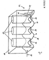
- FIG. 12 This shows schematically a preferred embodiment a fluid channel 10 around cylinder 12th an otherwise not shown internal combustion engine forming water box, by the arrow in the direction 14 a cooling fluid, such as Cooling water, flows.
- a cooling fluid such as Cooling water
- the fluid flows around the cylinder 12th and cools this by removing the fluid from the cylinder walls Heat energy removed.
- the water tank or the fluid channel 10 is limited in the bottom of a bottom 16.
- the floor 16 is formed as a curved surface, wherein the Surface in a cross-section along the flow direction Fig. 14 shows a sine wave waveform runs.
- wave peaks 18 and wave troughs 20 alternately on each other.
- the area of Soil 16 thus follows the flow of the fluid of this Sinusoid, whereby a formation of turbulence also at high flow velocities through such Maintaining the flow on the ground largely is avoided. Further, such a forced one improves Flow a distribution and mixing of the Fluids in the water tank, allowing better cooling with less fluid is possible.
- the curved surface of the bottom 16 is here exemplified such that substantially form 12 peaks 18 at the cylinders. This achieves a better controllability of a pipe distortion the cylinder 12 during operation of the Internal combustion engine by one according to the distribution the heat energy at the cylinder walls designed Um Togethergeometrie the fluid around the cylinder 12 around.
- an increase 24th provided, which extends from the bottom 16 in the direction of the cylinder head extends.
- This elevation 24 is designed such that that they are the mutual currents of the Fluid in the direction of the cylinder head in the Fig. Upwards deflects so that at a downstream end 26 of the Increase 24 the two partial flows without special Turbulences flow into each other.
- the increase 24 extends over a predetermined length in Direction of the cylinder head (in the direction towards above). In a preferred embodiment, elevates the elevation 24 over an entire height of the water box up to a parting line between cylinder block and cylinder head.
Landscapes
- Engineering & Computer Science (AREA)
- Chemical & Material Sciences (AREA)
- Combustion & Propulsion (AREA)
- Mechanical Engineering (AREA)
- General Engineering & Computer Science (AREA)
- Cylinder Crankcases Of Internal Combustion Engines (AREA)
Applications Claiming Priority (3)
| Application Number | Priority Date | Filing Date | Title |
|---|---|---|---|
| DE19812831A DE19812831A1 (de) | 1998-03-24 | 1998-03-24 | Brennkraftmaschine mit Fluidkühlsystem |
| DE19812831 | 1998-03-24 | ||
| PCT/EP1999/001045 WO1999049201A1 (de) | 1998-03-24 | 1999-02-17 | Brennkraftmaschine mit fluidkühlsystem |
Publications (3)
| Publication Number | Publication Date |
|---|---|
| EP1066459A1 EP1066459A1 (de) | 2001-01-10 |
| EP1066459B1 EP1066459B1 (de) | 2002-05-15 |
| EP1066459B2 true EP1066459B2 (de) | 2005-09-28 |
Family
ID=7862069
Family Applications (1)
| Application Number | Title | Priority Date | Filing Date |
|---|---|---|---|
| EP99906243A Expired - Lifetime EP1066459B2 (de) | 1998-03-24 | 1999-02-17 | Brennkraftmaschine mit fluidkühlsystem |
Country Status (7)
| Country | Link |
|---|---|
| US (1) | US6397792B1 (enExample) |
| EP (1) | EP1066459B2 (enExample) |
| JP (1) | JP4242068B2 (enExample) |
| CN (1) | CN1109191C (enExample) |
| DE (2) | DE19812831A1 (enExample) |
| ES (1) | ES2175947T5 (enExample) |
| WO (1) | WO1999049201A1 (enExample) |
Cited By (1)
| Publication number | Priority date | Publication date | Assignee | Title |
|---|---|---|---|---|
| WO2016179618A1 (de) | 2015-05-12 | 2016-11-17 | Avl List Gmbh | Flüssigkeitsgekühlte brennkraftmaschine |
Families Citing this family (6)
| Publication number | Priority date | Publication date | Assignee | Title |
|---|---|---|---|---|
| RU2230920C1 (ru) * | 2002-10-07 | 2004-06-20 | Гриценко Борис Петрович | Блок цилиндров двигателя внутреннего сгорания |
| JP4707648B2 (ja) * | 2006-12-14 | 2011-06-22 | ダイハツ工業株式会社 | 多気筒内燃機関用シリンダブロック |
| JP5974926B2 (ja) * | 2013-02-21 | 2016-08-23 | マツダ株式会社 | 多気筒エンジンの冷却構造 |
| DE102014222734A1 (de) | 2014-11-06 | 2016-05-12 | Volkswagen Aktiengesellschaft | Brennkraftmaschine mit einem die Brennräume umgebenden Kühlmittelmantel |
| CN106014668A (zh) * | 2016-08-03 | 2016-10-12 | 安徽江淮汽车股份有限公司 | 一种发动机及其缸体水套 |
| DE102017109185A1 (de) * | 2017-04-28 | 2018-10-31 | Volkswagen Aktiengesellschaft | Zylinderkopfgehäuse sowie Verfahren zur Herstellung eines Zylinderkopfgehäuses und Gießkern |
Family Cites Families (17)
| Publication number | Priority date | Publication date | Assignee | Title |
|---|---|---|---|---|
| DE294411C (enExample) * | ||||
| DE2058094A1 (de) * | 1969-12-31 | 1971-07-08 | Cunewalde Motoren | Fluessigkeitsgekuehlte mehrzylindrische Brennkraftmaschine |
| GB1468508A (en) | 1973-04-12 | 1977-03-30 | Perkins Engines Ltd | Engine cooling system |
| US4109617A (en) * | 1976-12-22 | 1978-08-29 | Ford Motor Company | Controlled flow cooling system for low weight reciprocating engine |
| JPS58156143U (ja) | 1982-04-15 | 1983-10-18 | 日産自動車株式会社 | シリンダブロツクのウオ−タジヤケツト構造 |
| DE3247663C1 (de) | 1982-12-23 | 1984-04-05 | Ford-Werke AG, 5000 Köln | Zylinderblock fuer einen Verbrennungsmotor |
| EP0184425A3 (en) * | 1984-12-03 | 1987-05-06 | Honda Giken Kogyo Kabushiki Kaisha | Closed-deck cylinder block for water-cooled internal combustion engine |
| DE3512104A1 (de) | 1985-04-03 | 1986-10-09 | Klöckner-Humboldt-Deutz AG, 5000 Köln | Brennkraftmaschine mit mindestens zwei hintereinanderliegenden fluessigkeitsgekuehlten zylindern |
| JP2568831B2 (ja) * | 1987-02-04 | 1997-01-08 | 本田技研工業株式会社 | 水冷エンジンのシリンダブロツク |
| FR2637941B1 (fr) * | 1988-10-18 | 1990-11-23 | Renault | Circuit de refroidissement pour moteur a combustion interne |
| US5115771A (en) * | 1989-08-30 | 1992-05-26 | Kabushiki Kaisha Komatsu Seisakusho | Method of cooling cylinder liners in an engine |
| DE4140772A1 (de) | 1990-12-14 | 1992-06-17 | Daimler Benz Ag | Vorrichtung zur kuehlung der stege zwischen zylindern eines zylinderblocks einer brennkraftmaschine |
| JPH06330808A (ja) * | 1993-05-26 | 1994-11-29 | Nissan Motor Co Ltd | 水冷式エンジンのシリンダブロック構造 |
| JP2914124B2 (ja) * | 1993-10-29 | 1999-06-28 | 日産自動車株式会社 | 内燃機関のウォータジャケット構造 |
| US5542381A (en) * | 1994-02-07 | 1996-08-06 | Nissan Motor Co., Ltd. | Cylinder block for liquid-cooled engine |
| DE4407984A1 (de) | 1994-03-10 | 1995-09-14 | Opel Adam Ag | Kühlsystem für eine Hubkolbenbrennkraftmaschine |
| US5746161A (en) * | 1995-07-05 | 1998-05-05 | Ford Motor Company | Engine cylinder block cooling passage |
-
1998
- 1998-03-24 DE DE19812831A patent/DE19812831A1/de not_active Ceased
-
1999
- 1999-02-17 JP JP2000538142A patent/JP4242068B2/ja not_active Expired - Fee Related
- 1999-02-17 WO PCT/EP1999/001045 patent/WO1999049201A1/de not_active Ceased
- 1999-02-17 US US09/646,997 patent/US6397792B1/en not_active Expired - Fee Related
- 1999-02-17 CN CN99804351A patent/CN1109191C/zh not_active Expired - Fee Related
- 1999-02-17 DE DE59901459T patent/DE59901459D1/de not_active Expired - Lifetime
- 1999-02-17 ES ES99906243T patent/ES2175947T5/es not_active Expired - Lifetime
- 1999-02-17 EP EP99906243A patent/EP1066459B2/de not_active Expired - Lifetime
Cited By (1)
| Publication number | Priority date | Publication date | Assignee | Title |
|---|---|---|---|---|
| WO2016179618A1 (de) | 2015-05-12 | 2016-11-17 | Avl List Gmbh | Flüssigkeitsgekühlte brennkraftmaschine |
Also Published As
| Publication number | Publication date |
|---|---|
| US6397792B1 (en) | 2002-06-04 |
| EP1066459A1 (de) | 2001-01-10 |
| ES2175947T5 (es) | 2006-03-01 |
| ES2175947T3 (es) | 2002-11-16 |
| CN1294656A (zh) | 2001-05-09 |
| EP1066459B1 (de) | 2002-05-15 |
| CN1109191C (zh) | 2003-05-21 |
| JP4242068B2 (ja) | 2009-03-18 |
| DE59901459D1 (de) | 2002-06-20 |
| JP2002507692A (ja) | 2002-03-12 |
| DE19812831A1 (de) | 1999-09-30 |
| WO1999049201A1 (de) | 1999-09-30 |
Similar Documents
| Publication | Publication Date | Title |
|---|---|---|
| EP1510681B1 (de) | Zylinderkopfdichtung | |
| DE102004004975A1 (de) | Plattenwärmeübertrager | |
| DE19654451C1 (de) | Flüssigkeitsgekühlte Mehrzylinder-Brennkraftmaschine | |
| EP0838585B1 (de) | Zylinderkopf einer Mehrzylinder-Brennkraftmaschine | |
| EP1066459B2 (de) | Brennkraftmaschine mit fluidkühlsystem | |
| AT402325B (de) | Zylinderkopf einer flüssigkeitsgekühlten brennkraftmaschine mit in reihe angeordneten zylindern | |
| DE3605825C1 (de) | Waermetauscher fuer zwei fluide Medien | |
| EP0819837B1 (de) | Kühlkreislauf einer Brennkraftmaschine | |
| AT515220B1 (de) | Zylinderblock einer Verbrennungskraftmaschine in Monoblock - Bauweise und Gießform zu dessen Herstellung | |
| DE102009008237B4 (de) | Brennkraftmaschine mit getrennten Kühlmittelräumen im Zylinderkopf | |
| DE19606972A1 (de) | Kühlkörper zum Kühlen von Leistungsbauelementen | |
| DE19503961C2 (de) | Zylinderblock für flüssigkeitsgekühlten Motor | |
| DE69611862T2 (de) | Kühlkanal für den Zylinderblock einer Brennkraftmaschine | |
| EP0878618A2 (de) | Flüssigkeitsgekühltes Zylinderkurbelgehäuse | |
| EP1736257B1 (de) | Flüssigkeitsgekühlte Kokille zum Stranggiessen von Metallen | |
| DE68922285T2 (de) | Stranggiesskokille mit direkter Kühlung mit verstellbarem Kühlmitteltreffpunkt. | |
| DE10203967A1 (de) | Kokillenrohr | |
| DE3702272C2 (enExample) | ||
| DE4140772C2 (enExample) | ||
| WO2019057408A1 (de) | Verbrennungsmotorgehäuse mit zylinderkühlung | |
| EP1795281B1 (de) | Stranggiesskokille | |
| DE10255316A1 (de) | Brennkraftmaschine mit angegossener Versteifungsrippe am Zylinderrohr | |
| DE10248663A1 (de) | Verbrennungsmotor mit einem Zylinderkurbelgehäuse... | |
| DE102018217652A1 (de) | Strömungsverteiler zum Kühlen einer elektrischen Baugruppe, ein Halbleitermodul mit einem derartigen Strömungsverteiler und ein Verfahren zu dessen Herstellung | |
| DE202010009777U1 (de) | Umlenkelement |
Legal Events
| Date | Code | Title | Description |
|---|---|---|---|
| PUAI | Public reference made under article 153(3) epc to a published international application that has entered the european phase |
Free format text: ORIGINAL CODE: 0009012 |
|
| 17P | Request for examination filed |
Effective date: 20001024 |
|
| AK | Designated contracting states |
Kind code of ref document: A1 Designated state(s): DE ES FR GB IT SE |
|
| GRAG | Despatch of communication of intention to grant |
Free format text: ORIGINAL CODE: EPIDOS AGRA |
|
| GRAG | Despatch of communication of intention to grant |
Free format text: ORIGINAL CODE: EPIDOS AGRA |
|
| GRAH | Despatch of communication of intention to grant a patent |
Free format text: ORIGINAL CODE: EPIDOS IGRA |
|
| 17Q | First examination report despatched |
Effective date: 20010726 |
|
| GRAH | Despatch of communication of intention to grant a patent |
Free format text: ORIGINAL CODE: EPIDOS IGRA |
|
| GRAA | (expected) grant |
Free format text: ORIGINAL CODE: 0009210 |
|
| AK | Designated contracting states |
Kind code of ref document: B1 Designated state(s): DE ES FR GB IT SE |
|
| REG | Reference to a national code |
Ref country code: GB Ref legal event code: FG4D Free format text: NOT ENGLISH |
|
| REF | Corresponds to: |
Ref document number: 59901459 Country of ref document: DE Date of ref document: 20020620 |
|
| GBT | Gb: translation of ep patent filed (gb section 77(6)(a)/1977) |
Effective date: 20020720 |
|
| PG25 | Lapsed in a contracting state [announced via postgrant information from national office to epo] |
Ref country code: SE Free format text: LAPSE BECAUSE OF FAILURE TO SUBMIT A TRANSLATION OF THE DESCRIPTION OR TO PAY THE FEE WITHIN THE PRESCRIBED TIME-LIMIT Effective date: 20020815 |
|
| REG | Reference to a national code |
Ref country code: ES Ref legal event code: FG2A Ref document number: 2175947 Country of ref document: ES Kind code of ref document: T3 |
|
| PLBQ | Unpublished change to opponent data |
Free format text: ORIGINAL CODE: EPIDOS OPPO |
|
| PLBI | Opposition filed |
Free format text: ORIGINAL CODE: 0009260 |
|
| PLBF | Reply of patent proprietor to notice(s) of opposition |
Free format text: ORIGINAL CODE: EPIDOS OBSO |
|
| 26 | Opposition filed |
Opponent name: PEUGEOT CITROEN AUTOMOBILES SA Effective date: 20030213 |
|
| PLBB | Reply of patent proprietor to notice(s) of opposition received |
Free format text: ORIGINAL CODE: EPIDOSNOBS3 |
|
| PUAH | Patent maintained in amended form |
Free format text: ORIGINAL CODE: 0009272 |
|
| STAA | Information on the status of an ep patent application or granted ep patent |
Free format text: STATUS: PATENT MAINTAINED AS AMENDED |
|
| 27A | Patent maintained in amended form |
Effective date: 20050928 |
|
| AK | Designated contracting states |
Kind code of ref document: B2 Designated state(s): DE ES FR GB IT SE |
|
| GBTA | Gb: translation of amended ep patent filed (gb section 77(6)(b)/1977) | ||
| REG | Reference to a national code |
Ref country code: ES Ref legal event code: DC2A Date of ref document: 20051104 Kind code of ref document: T5 |
|
| ET3 | Fr: translation filed ** decision concerning opposition | ||
| REG | Reference to a national code |
Ref country code: DE Ref legal event code: R084 Ref document number: 59901459 Country of ref document: DE Effective date: 20111008 |
|
| REG | Reference to a national code |
Ref country code: FR Ref legal event code: PLFP Year of fee payment: 17 |
|
| PGFP | Annual fee paid to national office [announced via postgrant information from national office to epo] |
Ref country code: IT Payment date: 20150227 Year of fee payment: 17 Ref country code: DE Payment date: 20150228 Year of fee payment: 17 Ref country code: ES Payment date: 20150326 Year of fee payment: 17 |
|
| PGFP | Annual fee paid to national office [announced via postgrant information from national office to epo] |
Ref country code: GB Payment date: 20150227 Year of fee payment: 17 Ref country code: FR Payment date: 20150227 Year of fee payment: 17 |
|
| REG | Reference to a national code |
Ref country code: DE Ref legal event code: R119 Ref document number: 59901459 Country of ref document: DE |
|
| GBPC | Gb: european patent ceased through non-payment of renewal fee |
Effective date: 20160217 |
|
| REG | Reference to a national code |
Ref country code: FR Ref legal event code: ST Effective date: 20161028 |
|
| PG25 | Lapsed in a contracting state [announced via postgrant information from national office to epo] |
Ref country code: IT Free format text: LAPSE BECAUSE OF NON-PAYMENT OF DUE FEES Effective date: 20160217 |
|
| PG25 | Lapsed in a contracting state [announced via postgrant information from national office to epo] |
Ref country code: FR Free format text: LAPSE BECAUSE OF NON-PAYMENT OF DUE FEES Effective date: 20160229 Ref country code: GB Free format text: LAPSE BECAUSE OF NON-PAYMENT OF DUE FEES Effective date: 20160217 Ref country code: DE Free format text: LAPSE BECAUSE OF NON-PAYMENT OF DUE FEES Effective date: 20160901 |
|
| PG25 | Lapsed in a contracting state [announced via postgrant information from national office to epo] |
Ref country code: ES Free format text: LAPSE BECAUSE OF NON-PAYMENT OF DUE FEES Effective date: 20160218 |