EP1066185B1 - Bremssteuerung für fahrzeuge, insbesondere für schienenfahrzeuge und verfahren zum steuern von fahrzeugbremsen - Google Patents
Bremssteuerung für fahrzeuge, insbesondere für schienenfahrzeuge und verfahren zum steuern von fahrzeugbremsen Download PDFInfo
- Publication number
- EP1066185B1 EP1066185B1 EP99907513A EP99907513A EP1066185B1 EP 1066185 B1 EP1066185 B1 EP 1066185B1 EP 99907513 A EP99907513 A EP 99907513A EP 99907513 A EP99907513 A EP 99907513A EP 1066185 B1 EP1066185 B1 EP 1066185B1
- Authority
- EP
- European Patent Office
- Prior art keywords
- signal
- bar
- deceleration
- brake command
- correction
- Prior art date
- Legal status (The legal status is an assumption and is not a legal conclusion. Google has not performed a legal analysis and makes no representation as to the accuracy of the status listed.)
- Expired - Lifetime
Links
- 238000000034 method Methods 0.000 title claims description 15
- 238000012937 correction Methods 0.000 claims description 41
- 238000005259 measurement Methods 0.000 claims description 12
- 230000008569 process Effects 0.000 claims description 4
- 230000003321 amplification Effects 0.000 claims 1
- 238000003199 nucleic acid amplification method Methods 0.000 claims 1
- 230000008859 change Effects 0.000 description 4
- 230000036461 convulsion Effects 0.000 description 4
- 238000001514 detection method Methods 0.000 description 4
- 238000004364 calculation method Methods 0.000 description 3
- 238000010586 diagram Methods 0.000 description 3
- 238000001914 filtration Methods 0.000 description 3
- 230000000903 blocking effect Effects 0.000 description 2
- 230000001934 delay Effects 0.000 description 2
- 238000011161 development Methods 0.000 description 2
- 230000018109 developmental process Effects 0.000 description 2
- 230000000694 effects Effects 0.000 description 2
- 238000009499 grossing Methods 0.000 description 2
- 230000001105 regulatory effect Effects 0.000 description 2
- 230000001133 acceleration Effects 0.000 description 1
- 230000006978 adaptation Effects 0.000 description 1
- 230000006399 behavior Effects 0.000 description 1
- 230000008901 benefit Effects 0.000 description 1
- 238000004590 computer program Methods 0.000 description 1
- 230000003247 decreasing effect Effects 0.000 description 1
- 230000004069 differentiation Effects 0.000 description 1
- 230000006870 function Effects 0.000 description 1
- 230000001939 inductive effect Effects 0.000 description 1
- 230000007246 mechanism Effects 0.000 description 1
- 239000013642 negative control Substances 0.000 description 1
- 238000010606 normalization Methods 0.000 description 1
- 239000013641 positive control Substances 0.000 description 1
- 238000012545 processing Methods 0.000 description 1
- 238000005070 sampling Methods 0.000 description 1
- 230000009466 transformation Effects 0.000 description 1
- 238000000844 transformation Methods 0.000 description 1
Images


Classifications
-
- B—PERFORMING OPERATIONS; TRANSPORTING
- B60—VEHICLES IN GENERAL
- B60T—VEHICLE BRAKE CONTROL SYSTEMS OR PARTS THEREOF; BRAKE CONTROL SYSTEMS OR PARTS THEREOF, IN GENERAL; ARRANGEMENT OF BRAKING ELEMENTS ON VEHICLES IN GENERAL; PORTABLE DEVICES FOR PREVENTING UNWANTED MOVEMENT OF VEHICLES; VEHICLE MODIFICATIONS TO FACILITATE COOLING OF BRAKES
- B60T13/00—Transmitting braking action from initiating means to ultimate brake actuator with power assistance or drive; Brake systems incorporating such transmitting means, e.g. air-pressure brake systems
- B60T13/10—Transmitting braking action from initiating means to ultimate brake actuator with power assistance or drive; Brake systems incorporating such transmitting means, e.g. air-pressure brake systems with fluid assistance, drive, or release
- B60T13/66—Electrical control in fluid-pressure brake systems
-
- B—PERFORMING OPERATIONS; TRANSPORTING
- B60—VEHICLES IN GENERAL
- B60T—VEHICLE BRAKE CONTROL SYSTEMS OR PARTS THEREOF; BRAKE CONTROL SYSTEMS OR PARTS THEREOF, IN GENERAL; ARRANGEMENT OF BRAKING ELEMENTS ON VEHICLES IN GENERAL; PORTABLE DEVICES FOR PREVENTING UNWANTED MOVEMENT OF VEHICLES; VEHICLE MODIFICATIONS TO FACILITATE COOLING OF BRAKES
- B60T13/00—Transmitting braking action from initiating means to ultimate brake actuator with power assistance or drive; Brake systems incorporating such transmitting means, e.g. air-pressure brake systems
- B60T13/10—Transmitting braking action from initiating means to ultimate brake actuator with power assistance or drive; Brake systems incorporating such transmitting means, e.g. air-pressure brake systems with fluid assistance, drive, or release
- B60T13/66—Electrical control in fluid-pressure brake systems
- B60T13/665—Electrical control in fluid-pressure brake systems the systems being specially adapted for transferring two or more command signals, e.g. railway systems
Definitions
- the invention relates to a brake control according to the preamble of the claim 1 and to a method according to the preamble of the claim 10th
- Such a device is known from US 4,743,072.
- a brake pressure control device described for vehicles in which the driver has a Brake value transmitter a brake request signal or a desired vehicle deceleration specifies and the actual vehicle deceleration measured by wheel sensors becomes.
- the control device has a correction value device, which at a control deviation between the braking request signal and the measured Vehicle deceleration modified the brake pressure control so that the driver requested vehicle deceleration is reached. It is a classic, continuous control, with multiple channels for individual control the delay of individual wheels are provided.
- US 4,805,105 describes a brake pressure control device for road vehicles, a control intervention only takes place if the difference between that of the driver requested brake pressure and the actual brake pressure outside of a given range.
- EP 0,630,788 A1 describes an electronic pressure control device for a multi-axle road vehicle in which load sensors are provided and Brake pressure is regulated depending on the measured axle loads.
- US 5,501,512 describes a device for the calibration of pressure transducers an electro-pneumatic brake control of towing vehicles.
- a major problem is that when actuating actuators Rail vehicle brake systems have relatively long dead times that occur in trams typically in the range of 0.7 seconds; furthermore becomes Braking force build-up takes a relatively long period of time (swell time), which is typically is in the range of 1 second.
- the object of the invention is therefore to provide a brake control and a method create with which or with a stable braking according to the driver's specified Braking request for any parameters influencing braking is feasible.
- the basic principle of the invention consists in subordinating the control to a regulation, which intervenes with a correction signal only if the deviation between the braking request (as the target deceleration signal) and the actual deceleration of the vehicle is outside a predetermined range. That corrected The braking request signal is then constant for the further control as long as the said deviation lies within the specified range. A change only then will the correction signal take effect. if the said deviation is outside the specified range.
- the correction signal is kept constant over one or more time cycles. than the difference between the "instantaneous deceleration signal" and the target deceleration signal is within a specified range of values. However, will the correction signal changes from one clock cycle to the next when the mornentan delay lies outside this "tolerance band".
- a manipulated variable is continuous during the entire control process is returned and processed in the signal processing according to the invention only processes the instantaneous delay that can be understood as a manipulated variable, d. H. used to generate the correction signal if the "control deviation" understandable difference between the target deceleration signal and the instantaneous deceleration is too large in amount, d. H. outside the tolerance band lies. If, on the other hand, the control deviation is so small that the difference is within the tolerance band the instantaneous delay is not processed and the correction signal is kept unchanged.
- the invention is both as a hardware solution in the form of an electronic circuit as well as a software solution in the form of a computer program for a program-controlled Processor or as a combination of both solutions.
- a software implementation allows a very inexpensive one Adaptation of the existing brake control to a specific vehicle and certain conditions of use.
- a smooth instantaneous delay signal is formed.
- the smoothing takes place through a special filtering, which consists in that a number successively in time measured values taken are weighted differently and weighted from these A weighted average is formed.
- the weighting is included so determined that the measured values close in time to the current measurement time are higher are weighted as the measured values further away in time, in contrast to one Frequency filtering, for example with a low-pass filter, you get none Signal transformations in the time domain.
- a two successive correction signals formed "Correction signal gradient" when exceeding or falling below a given positive or negative Maximum gradients limited to this. This has the advantage that delays and resulting Power surges on the vehicle or within one Vehicle network continues during the braking process be minimized. This reduces the mechanical Load on the vehicle, while the Driving comfort increased for the passengers.
- an encoder G generates, for example, a Brake levers can be a mechanical signal that by a mechanical-electrical converter 1 'in analog electrical brake request signal BAZ for the train unit is converted and one by the driver requested target deceleration of the vehicle to be braked represents.
- This brake request signal BAZ is via a signal converter 1 with integrated A / D converter as a digital signal BA a jerk limiting circuit 3 supplied, the rise and Drop gradients of the signal BA limited and a Outputs "filtered" brake request signal BAR.
- This filtered brake request signal is BAR the "normal" output signal of the control, the actuators is fed to the brake. In the invention this signal becomes when certain operating conditions occur modified.
- a summer 5 provided, the one input the signal BAR and whose other input is supplied with a correction signal K. becomes. The output of the summer 5 then provides that Actuators of the brake control signal supplied S.
- the correction signal K is generated in a subordinate control loop.
- a sensor M determines, by measuring the speed of one or more wheels of the vehicle, a signal v representing the instantaneous speed of the vehicle, which is differentiated in time in a differentiator 8, with which a signal b i representing the vehicle acceleration or deceleration is obtained.
- This signal - referred to below as the delay signal - is temporarily stored in a memory element 10, the memory element 10 being able to store a plurality of successive measured values, for example four or five successive delay signals.
- the delay signal measured at the current time and determined several from previous measurements and delay signals stored in the memory element previous timings become a filter element 11 supplied and "filtered" by this.
- the filter element 11 is a digital numerical filter which generally speaking only carries out an amplitude normalization of successive delay signals, but does not carry out frequency filtering and thus smoothes the time behavior of the signal curve formed by the delay signals.
- the basic principle of this filter is that the current delay value is multiplied by a relatively high weighting factor, while the delay values of the previous measurements are multiplied by smaller weighting factors.
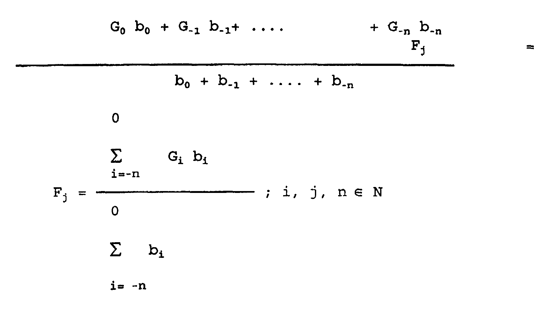
- the individual multiplied values are added and divided by the sum of the individual weighting factors. This relationship is expressed in the following calculation formula:
- F j is a delay signal smoothed by the filter element 11 at the time j, which corresponds to the smoothed signal b of FIG. 1.
- F j is calculated from individual delay values b i , where b o corresponds to the value of the instantaneous delay signal of the currently considered time cycle, b -1 to that of the previous time cycle, etc.
- the factors G i are weighting factors which are indexed in accordance with the delay values b i , where applies here, G i > G i-1 .
- the "past" has a lower weight than the "present", but still effects a smoothing, so that undesired peaks in the delay signal b are avoided.
- the smoothed delay signal b becomes a subtractor 13 supplied and there by the filtered brake request signal BAR subtracted.
- the so generated Difference signal ⁇ b is two via a switch 15 Comparators 17 and 18 fed.
- the switch 15 is used to the subordinate in certain operating states Switch off the control loop, for example when falling below a predetermined minimum speed of the Vehicle, in certain blocking conditions, for example when all the wheels of the vehicle are blocking incline when the vehicle's parking brake is applied is, etc. In the normal state, the switch 15 is in the shown ON position.
- the comparators 17 and 18 are multipliers, respectively 19 and 20 downstream, the arrangement of the comparators 17 and 18 and the multiplier 19 and 20 has the purpose for positive and negative control deviation signals ⁇ b different control gains provided.
- the comparator 17 therefore leaves only one sigrial ⁇ b through, which is> 0, while the comparator 18 only allows a signal ⁇ b that is ⁇ 0.
- the multipliers 19 and 20 become the corresponding signals then multiplied by different factors K1 and K2. If the signal ⁇ b is exactly 0, then both are comparators 17 and 18 blocked, a "rule intervention" is not mandatory.
- the output signals of the multipliers 19 and 20 become a common connection a switch 22 supplied by a logical Signal F of a window comparator 24 is controlled.
- the window comparator 24 receives the filtered braking request signal BAR and the smoothed delay signal b fed.
- the brake request signal BAR is multiplied by a factor in a first multiplier 31 A1 and in a second multiplier 32 by one Multiplied factor A2.
- the output signals of the multipliers 31 and 32 are compared in comparisons 33 and 34 compared with the delay signal b.
- the comparators 33 and 34 are threshold comparators 35 and 36 downstream, in which it is checked whether the output signal of comparator 33 is less than or equal to 0 or whether the output signal of the comparator 34 is greater than 0 is.
- the output signals of the two comparators 35 and 36 are linked together in an AND gate 38, that outputs the signal F.
- the window comparator 24 results in a Range of values of (BAR * A1 - b) and (BAR * A2 - b) defined and checks whether the smoothed delay signal b within this range of values or window lies. Width and position of this window in relation to the smoothed delay value b are by the factors A1 and A2 determined. Is the smoothed delay signal b within the window so defined, so is not a correction of the brake request signal BAR required. In contrast, the signal b lies outside of this Window, so is the switch 22 in FIG.
- the output signal K of the memory 28 is in one Comparator 50 with a fixed predetermined negative Value -x compared.
- the output signal of the comparator 50 controls the switch 52.
- the purpose of this measure is es, negative correction values only up to a fixed predetermined Allow value -x.
- the driver controlled Brake request signal BAR can only be used for this Value -x can be decreased. This will, for example a complete release of the brake on one Uphill braking prevented.
- Is the output signal K of memory 28 negative and mathematically less than the value -x the switch 52 is switched and the corresponding input of the summer 5 is a 'Fixed value -x supplied.
- the value -x can also be zero can be selected if there is no braking request BAR reducing corrections but only the braking request BAR enlargement corrections are allowed should.
- FIG. 1 shows the output of the memory 28 with the other Input 30 of switch 22 connected so that the output value of the memory 28 via the switch 22 and the Gradient limiting circuit 25 the input of the Memory 28 is supplied.
- the constant A1 has the value 1.0 and the constant A2 has the value 1.1 from the window comparator output logic signal F exactly then logic value "1" if the value of the delay signal b in a range between 1.0 times the value of the brake request signal BAR and 1.1 times of the signal BAR.
- the smoothed delay signal b outside of this by the two Constants A1 and A2 depending on the value of the signal BAR defined "tolerance range", so it has signal F output by the window comparator 24 is the logical one Value "0", which is the position of the switch shown 22 corresponds.
- this is from the speed signal v formed smoothed delay signal b is equal to 0.95 times the filtered braking request signal BAR, i.e. is the actual delay less than the deceleration requested by the driver, the signal b lies outside the tolerance band.
- the signal F has a logical value "0" so that switch 22 is in the position shown and the storage element 28 is ready for storage State is switched. Because the actual delay of the vehicle is smaller than that requested by the driver Is delay, the difference signal is ⁇ b positive and is therefore in multiplier 19 with the Factor K1 multiplied and as signal 21 is over the Switch 22 to the gradient limiting circuit 25 output.
- the signal 26 increases its value with the gradient that provided by the gradient limiting circuit 25 is.
- the memory 28 increases according to its stored Value. This value is set via switch 52 output as correction value K in the position shown and added to the braking request signal BA and that Signal S rises accordingly.
- the vehicle deceleration increases and as long as the delivered Delay signal b in the permissible value range of Window comparator 24 arrives, with its output signal F assumes the logical value "1".
- the value in Memory 28 remains unchanged as long as signal F has a logical value of "1".
- case 2 the delay signal b was compared case 1 is enlarged and is, for example, the same 1.05 times the braking request signal BAR and lies thus within the tolerance range.
- the signal F has in this case the logical value "1" and switches the Switch 22 to contact 30 and switches at the same time the readiness for storage of the storage element 28.
- a differential signal continues to be ⁇ b and from this a signal 21 is generated, however is no longer processed.
- the value 29 of the previous one stored in memory 28 Timing again the summer 5 as a correction signal K supplied and the output signal S formed therefrom.
- Clock - for example in a subsequent one Clock - be the smoothed delay signal b equal to 1.2 times the filtered brake request signal BAR and is again outside of the tolerance band, so that the switch 22 is back in the position shown is switched back and that Storage element 28 set in the ready state becomes.
- the difference signal ⁇ b is negative in this case and is multiplied in the multiplier 20 by the factor K2.
- After going through the gradient limiting circuit 25 will be the new value 29 in the Memory 28 written and as the correction signal K the Totalizer 5 supplied.
- the smoothed delay signal b is equal to the filtered brake request signal BAR, so that the difference signal ⁇ b has the value "0" and the switch 15 switches, resulting in that at all no correction signal K is output. So is the output signal S is equal to the filtered brake request signal BAR.
- Control with control intervention in a total brake system can be integrated that they in certain operating states through the switch 15 automatically or is switched off manually or by another subsystem, such as. switched off an anti-skid system or can be overridden.
- One shutdown and one Intervention of an anti-skid system is for example then makes sense if all axles of a vehicle or a group of vehicles tend to block.
- FIG. 2 shows a schematic block diagram, in which the deceleration control shown in FIG. 1 with control intervention is part of an overall braking system of a vehicle.
- the delay control with control intervention shown in FIG. 1 is summarized in FIG. 2 in a block denoted by R.
- the braking request signal BAZ specified by the driver is entered into the block R, and the deceleration signal b i obtained from the vehicle speed v by differentiation in the differentiator 8.
- the delay control with control intervention generates the control signal S from the signals BAZ and b i , which is fed to a load detection unit L.
- Load signals LS are also fed to load detection unit L, only one signal path LS being shown in the schematic illustration in FIG. 2.
- a train's braking system corresponds to the number of load signals LS, for example the number of bogies on the train, i.e. it will be the load to be carried by each bogie.
- the Load detection unit L In Dependence on the possibly different Loads on individual bogies is reduced by the Load detection unit L a corresponding number of Output signals 44 generated, which are fed to a converter 45 become.
- the electro-pneumatic converter 45 converts, for example the signals 44 into forces or pressures that Brake mechanisms 47 (e.g. brake cylinders or brake calipers) press at the assigned bogies what slows down and thus the speed v changed. From a new yourself in the next clock adjusting speed v becomes a new delay b is calculated again the delay control is supplied with control intervention R.
- Brake mechanisms 47 e.g. brake cylinders or brake calipers
- the additional detection of load signals LS is advantageous to, for example, the situation on a train to prevent the generated from the brake control signal S. Braking forces only the brakes of a bogie are fed while the other bogies are not braked stay.
Landscapes
- Engineering & Computer Science (AREA)
- Transportation (AREA)
- Mechanical Engineering (AREA)
- Regulating Braking Force (AREA)
Description
- Fig. 1
- Ein Blockschaltbild einer Bremssteuerung nach der Erfindung und
- Fig. 2
- ein schematisches Blockschaltbild einer Bremsanlage eines Fahrzeuges, die mit einer erfindungsgemäßen Bremssteuerung ausgestattet ist.
Claims (17)
- Bremssteuerung für Fahrzeuge, insbesondere Schienenfahrzeuge, mit
einem vom Fahrer betätigbaren Geber zur Erzeugung eines
Bremsanforderungssignals (BAZ) und einer mit dem Geber verbundenen Steuerung, die in Abhängigkeit von dem Bremsanforderungssignat ein bremssteuemdes Ausgangssignal (S) erzeugt;dadurch gekennzeichnet, daßeiner Meßeinrichtung (8, 10, 11), die ein der Fahrzeugverzögerung entsprechendes Verzögerungssignal (b) erzeugt;einer Korrekturwerteinrichtung (6), die ein der Differenz zwischen dem Bremsanforderungssignal (BAR) und dem Verzögerungssignal (b) entsprechendes Korrektursignal (K) erzeugt, undeiner Verknüpfungseinrichtung (5), die das Bremsanforderungssignal (BAR) entsprechend dem Korrektursignal (K) modifiziert,wobei eine Modifikation des Bremsanforderungssignals (BAR) mit einem gegenüber der Vergangenheit veränderten Korrektursignal (K) nur dann erfolgt, wenn das Ausgangssignal (F) des Fensterkomparators (24) angibt, daß die Differenz zwischen dem Bremsanforderungssignal (BAR) und dem Verzögerungssignal (b) außerhalb des vordefinierten Bereiches liegt undein Fensterkomparator (24) vorgesehen ist, der überprüft, ob eine Differenz zwischen dem Bremsanforderungssignal (BAR) und dem Verzögerungssignal (b) innerhalb eines vordefinierten Bereiches liegt und der ein dem Ergebnis dieser Überprüfung entsprechendes Ausgangssignal (F) erzeugt,
daß die Meßeinrichtung (8, 10, 11) eine Filtereihrichtung (10, 11) aufweist, die mehrere aufeinanderfolgende zeitdiskrete Meßwerte (bi) mehrerer aufeinanderfolgend gemessener Verzögerungssignale (bi) zu dem Verzögerungssignal (b) verarbeitet. - Bremssteuerung nach Anspruch 1,
dadurch gekennzeichnet, daß die Filtereinrichtung (10, 11), die während eines Zeittaktes zu verarbeitenden Meßwerte (bi) unterschiedlich stark gewichtet. - Bremssteuerung nach Anspruch 2,
dadurch gekennzeichnet, daß die Gewichtung mittels unterschiedlicher Gewichtungsfaktoren (G1) erfolgt,
wobei zeitlich später gemessene Meßwerte (b1) stärker gewichtet werden als zeitlich früher gemessene Meßwerte (bi). - Bremssteuerung nach einem der Ansprüche 1 bis 3,
dadurch gekennzeichnet, daß die Korrekturwerteinrichtung (6) eine Gradientenbegrenzungseinrichtung (25) ausweist, die die zeitliche Änderung des Korrektursignals (K, 26, 29) auf einen vorgegebenen Betrag begrenzt. - Bremssteuerung nach Anspruch 4,
dadurch gekennzeichnet, daß die Korrekturwerteinrichtung (6) eine Speichereinrichtung (28) aufweist, die ein von der Gradientenbegrenzungseinrichtung (25) geliefertes Signal (29) speichert, wenn das vom Fensterkomparator (24) gelieferte Ausgangssignal (F) einen vorgegebenen Wert hat. - Bremssteuerung nach einem der Ansprüche 1 bis 5,
dadurch gekennzeichnet, daß die Korrekturwerteinrichtung (6) eine Regelverstärkungseinrichtung (19, 20, 22) aufweist, die ein aus dem Bremsanforderungssignal (BAR) und dem Verzögerungssignal (b) gebildetes Differenzsignal (Db) in Abhängigkeit von dessen Vorzeichen unterschiedlich stark verstärkt und an die Gradientenbegrenzungseinrichtung (25) liefert, wenn das vom Fensterkomparator (24) erzeugte Ausgangssignal (F) einen vorgegebenen Wert hat. - Bremssteuerung nach einem der Ansprüche 1 bis 6,
dadurch gekennzeichnet, daß die Korrekturwerteinrichtung (6) eine Begrenzungseinrichtung (50, 52) aufweist, die ein zur Verminderung des Bremsanforderungssignals (BAR) erzeugtes Korrektursignal (K) auf einen vorgegebenen Betrag (-x) begrenzt. - Bremssteuerung nach einem der Ansprüche 1 bis 7,
dadurch gekennzeichnet, daß eine Schalteinrichtung (15) vorgesehen ist, welche die Korrekturwerteinrichtung (6) in Abhängigkeit von vorgegebenen Bedingungen, wie einer Fahrzeuggeschwindigkeit, einem Wert eines Gleitschutzsignals, einem Wert eines Bremssignals, den Typen aneinandergekoppelter Fahrzeuge oder ähnlichem, ein-bzw. ausschaltet. - Bremssteuerung nach einem der Ansprüche 1 bis 8,
dadurch gekennzeichnet, daß eine Ruckbegrenzungseinrichtung (3) vorgesehen ist, die aus einem von dem Geber (G) gelieferten Signal (BAZ) das Bremsanforderungssignal (BAR) erzeugt und die die zeitliche Änderung des Bremsanforderungssignals (BAR) auf einen vorgegebenen Betrag begrenzt. - Verfahren zur Steuerung von Fahrzeugbremsen, insbesondere von Schienenfahrzeugbremsen, bei dem aus einem von einem Fahrer vorzugebenden Bremsanforderungssignal ein bremssteuemdes Bremsausgangssignal erzeugt wird
mit den Schritten:entsprechend dem Korrektursignal (K),Messen der Fahrzeugverzögerung (bi) und Erzeugung eines entsprechenden Verzögerungssignals (b);Ermitteln einer Differenz zwischen dem Bremsanforderungssignal (BAR) und dem Verzögerungssignal (b);Erzeugen eines der Differenz zwischen dem Bremsanforderungssignal (BAR) und dem Verzögemngssignal (b) entsprechenden Korrektursignals (K),
Modifizieren des Bremsanforderungssignals (BAR),
dadurch gekennzeichnet, daß
überprüft wird, ob die Differenz innerhalb oder außerhalb eines vorgegebenen Bereiches liegt,
das Bremsanforderungssignal (BAR) nur dann modifiziert wird, wenn die Differenz zwischen dem Bremsanforderungssignal (BAR) und dem Verzögerungssignal (b) außerhalb des vorgegebenen Bereiches liegt und daß
mehrere zeitdiskrete Meßwerte (bi) mehrerer aufeinanderfolgend gemessener Verzögerungssignale zu dem Verzögerungssignal (b) verarbeitet werden. - Verfahren nach Anspruch 10,
gekennzeichnet durch
eine unterschiedlich starke Gewichtung der während eines Zeittaktes zu verarbeitenden Meßwerte (bi). - Verfahren nach Anspruch 11,
gekennzeichnet durch
eine Gewichtung mit Gewichtungsfaktoren (G1), bei der zeitlich später gemessene Meßwerte (bi) stärker gewichtet werden als zeitlich früher gemessene Meßwerte (bi). - Verfahren nach einem der Ansprüche 10 bis 12,
gekennzeichnet durch
eine Begrenzung der zeitlichen Änderung des Korrektursignals (K) auf einen vorgegebenen Betrag. - Verfahren nach Anspruch 13,
gekennzeichnet durch
eine Speicherung des gegebenenfalls begrenzten Korrektursignals (K) unter der Bedingung, daß die Differenz zwischen dem Bremsanforderungssignal (BAR) und dem Verzögerungssignal (b) innerhalb des vorgegebenen Bereiches liegt. - Verfahren nach einem der Ansprüche 10 bis 14,
dadurch gekennzeichnet, daß eine Verstärkung eines aus dem Bremsanforderungssignal (BAR) und dem Verzögerungssignal (b) gebildeten Differenzsignals (Db) durchgeführt wird,
wobei das Differenzsignal (Db) in Abhängigkeit von seinem Vorzeichen unterschiedlich verstärkt wird. - Verfahren nach einem der Ansprüche 10 bis 15,
gekennzeichnet durch
eine Begrenzung eines zur Verminderung des Bremsanforderungssignals (BAR) erzeugten Korrektursignals (K), auf einen vorgegebenen Betrag (-x). - Verfahren nach einem der Ansprüche 10 bis 16,
dadurch gekennzeichnet, daß die Erzeugung eines Korrektursignals (K) in Ab hängigkeit von vorgegebenen Bedingungen wie einer Fahrzeuggeschwindigkeit, einem Wert eines Gleitschutzsignals, einem Wert eines Bremssignals, den Typen aneinandergekoppelter Fahrzeuge oder ähnlichem durchgeführt wird oder nicht durchgeführt wird.
Applications Claiming Priority (3)
| Application Number | Priority Date | Filing Date | Title |
|---|---|---|---|
| DE19804570 | 1998-02-05 | ||
| DE19804570A DE19804570C2 (de) | 1998-02-05 | 1998-02-05 | Bremssteuerung für Fahrzeuge, insbesondere für Schienenfahrzeuge und Verfahren zum Steuern von Fahrzeugbremsen |
| PCT/EP1999/000790 WO1999039957A1 (de) | 1998-02-05 | 1999-02-05 | Bremssteuerung für fahrzeuge, insbesondere für schienenfahrzeuge und verfahren zum steuern von fahrzeugbremsen |
Publications (2)
| Publication Number | Publication Date |
|---|---|
| EP1066185A1 EP1066185A1 (de) | 2001-01-10 |
| EP1066185B1 true EP1066185B1 (de) | 2002-09-18 |
Family
ID=7856742
Family Applications (2)
| Application Number | Title | Priority Date | Filing Date |
|---|---|---|---|
| EP99101547A Withdrawn EP0934861A3 (de) | 1998-02-05 | 1999-01-29 | Bremssteuerung für Fahrzeuge, insbesondere für Schienenfahrzeuge und Verfahren zum Steuern von Fahrzeugbremsen |
| EP99907513A Expired - Lifetime EP1066185B1 (de) | 1998-02-05 | 1999-02-05 | Bremssteuerung für fahrzeuge, insbesondere für schienenfahrzeuge und verfahren zum steuern von fahrzeugbremsen |
Family Applications Before (1)
| Application Number | Title | Priority Date | Filing Date |
|---|---|---|---|
| EP99101547A Withdrawn EP0934861A3 (de) | 1998-02-05 | 1999-01-29 | Bremssteuerung für Fahrzeuge, insbesondere für Schienenfahrzeuge und Verfahren zum Steuern von Fahrzeugbremsen |
Country Status (7)
| Country | Link |
|---|---|
| US (1) | US6314358B1 (de) |
| EP (2) | EP0934861A3 (de) |
| KR (1) | KR100577866B1 (de) |
| AU (1) | AU2723999A (de) |
| DE (2) | DE19804570C2 (de) |
| WO (1) | WO1999039957A1 (de) |
| ZA (1) | ZA99917B (de) |
Families Citing this family (15)
| Publication number | Priority date | Publication date | Assignee | Title |
|---|---|---|---|---|
| DE10005424A1 (de) * | 2000-02-08 | 2001-08-09 | Bosch Gmbh Robert | Steuerschaltung für ein steuerbares Elektro-Magnetventil einer Bremsanlage eines Kraftfahrzeugs |
| DE10021135B4 (de) * | 2000-04-29 | 2007-08-30 | Bayerische Motoren Werke Ag | Verfahren und Vorrichtung zur Regelung einer vorgegebenen Soll-Verzögerung eines Kraftfahrzeugs |
| KR101065643B1 (ko) | 2005-12-09 | 2011-09-20 | 주식회사 만도 | 차량의 제동장치 제어방법 |
| US7454298B2 (en) * | 2006-07-31 | 2008-11-18 | Caterpillar Inc. | Apparatus and method for identifying electrical faults |
| US9254749B2 (en) * | 2007-06-07 | 2016-02-09 | GM Global Technology Operations LLC | Cruise control interaction with driver commanded speed reset |
| DE102007034265A1 (de) * | 2007-07-18 | 2009-01-22 | Siemens Ag | Verfahren zum Betreiben eines Fahrzeugverbands mit einem Zugfahrzeug sowie einem mit dem Zugfahrzeug verbundenen Schienenfahrzeug, Zugfahrzeug, Schienenfahrzeug sowie Fahrzeugverband |
| DE102008027520A1 (de) * | 2008-06-10 | 2010-01-14 | Siemens Aktiengesellschaft | Verfahren für ein Schienenfahrzeug zur Anforderung von Sicherheitsreaktionen |
| DE102011052545B4 (de) | 2011-08-10 | 2013-04-11 | Bombardier Transportation Gmbh | Bremssteuerung für ein Fahrzeug |
| US9283945B1 (en) | 2013-03-14 | 2016-03-15 | Wabtec Holding Corp. | Braking systems and methods of determining a safety factor for a braking model for a train |
| AU2014200345B2 (en) | 2013-05-17 | 2019-09-26 | Wabtec Holding Corp. | Braking Systems And Methods For Determining Dynamic Braking Data For A Braking Model For A Train |
| DE102014102881A1 (de) | 2014-03-05 | 2015-09-10 | Knorr-Bremse Systeme für Schienenfahrzeuge GmbH | Verfahren zur Steuerung einer Bremsanlage eines Schienenfahrzeugs |
| US10279823B2 (en) * | 2016-08-08 | 2019-05-07 | General Electric Company | System for controlling or monitoring a vehicle system along a route |
| DE102018215108B4 (de) | 2018-09-05 | 2026-03-05 | Knorr-Bremse Systeme für Schienenfahrzeuge GmbH | System zur Diagnose und Überwachung von Luftversorgungsanlagen und deren Komponenten |
| DE102019108447A1 (de) * | 2019-04-01 | 2020-10-01 | Knorr-Bremse Systeme für Schienenfahrzeuge GmbH | Bremsregeleinrichtung, Bremsverfahren und Bremssystem für ein Schienenfahrzeug |
| JP7327285B2 (ja) * | 2020-06-01 | 2023-08-16 | トヨタ自動車株式会社 | 制動制御装置及び制動制御方法 |
Family Cites Families (18)
| Publication number | Priority date | Publication date | Assignee | Title |
|---|---|---|---|---|
| US3717384A (en) * | 1971-03-15 | 1973-02-20 | Gen Motors Corp | Anti-lock brake control system |
| JPS5612801A (en) * | 1979-07-13 | 1981-02-07 | Hitachi Ltd | Method of stopping vehicle in fixed position |
| US4401035A (en) * | 1980-07-03 | 1983-08-30 | Kansas City Southern Railway Company | Control device for multiple unit locomotive systems |
| DE3130019A1 (de) * | 1981-07-30 | 1983-03-17 | Wabco Westinghouse Fahrzeugbremsen GmbH, 3000 Hannover | Blockiergeschuetzte fahrzeugbremsanlage |
| KR910008882B1 (ko) * | 1982-04-27 | 1991-10-24 | 가부시기가이샤 히다찌세이사꾸쇼 | 정위치 정차방법 및 장치 |
| US4671576A (en) * | 1985-03-06 | 1987-06-09 | Wabco Westinghouse (Railway Brake) (Pty.) Ltd. | Deceleration control system |
| GB8513688D0 (en) * | 1985-05-30 | 1985-07-03 | Lucas Ind Plc | Vehicle braking system |
| DE3543145C2 (de) * | 1985-12-06 | 1995-08-03 | Bosch Gmbh Robert | Elektrisches Bremssystem für ein Fahrzeug |
| US5209551A (en) * | 1991-05-28 | 1993-05-11 | Westinghouse Air Brake Company | Analog service brake response enhancing circuit for railway vehicles |
| US5333944A (en) * | 1991-08-06 | 1994-08-02 | Toyota Jidosha Kabushiki Kaisha | Electrically controlled vehicle brake system having means for controlling braking based on detected actual braking effect and determined target value |
| GB9313218D0 (en) * | 1993-06-26 | 1993-08-11 | Lucas Ind Plc | Electronic braking system with system test |
| JP3505815B2 (ja) * | 1993-11-25 | 2004-03-15 | 住友電気工業株式会社 | 前後加速度センサ異常検出装置 |
| DE4429231C1 (de) * | 1994-08-18 | 1995-08-31 | Daimler Benz Ag | Verfahren zur lastabhängigen Bremsdruckregelung einer Fahrzeugkombination aus Zug- und Anhängefahrzeug |
| JPH0885431A (ja) * | 1994-09-20 | 1996-04-02 | Sumitomo Electric Ind Ltd | 車両の制動力制御装置 |
| US5501512A (en) * | 1995-06-27 | 1996-03-26 | Westinghouse Air Brake Company | System and method for automatically calibrating transducers in electro-pneumatic freight brake control systems |
| JPH106963A (ja) * | 1996-06-20 | 1998-01-13 | Nisshinbo Ind Inc | ブレーキバルブ制御方法 |
| DE19726116B4 (de) * | 1997-06-20 | 2016-12-08 | Wabco Gmbh | Verfahren zur Abbremsung eines Fahrzeugs |
| US6167979B1 (en) * | 1998-05-20 | 2001-01-02 | Cummins Engine Company, Inc. | Dynamic speed governing of a vehicle |
-
1998
- 1998-02-05 DE DE19804570A patent/DE19804570C2/de not_active Expired - Fee Related
-
1999
- 1999-01-29 EP EP99101547A patent/EP0934861A3/de not_active Withdrawn
- 1999-02-05 EP EP99907513A patent/EP1066185B1/de not_active Expired - Lifetime
- 1999-02-05 WO PCT/EP1999/000790 patent/WO1999039957A1/de not_active Ceased
- 1999-02-05 DE DE59902754T patent/DE59902754D1/de not_active Expired - Lifetime
- 1999-02-05 ZA ZA9900917A patent/ZA99917B/xx unknown
- 1999-02-05 US US09/601,640 patent/US6314358B1/en not_active Expired - Lifetime
- 1999-02-05 KR KR1020007008579A patent/KR100577866B1/ko not_active Expired - Lifetime
- 1999-02-05 AU AU27239/99A patent/AU2723999A/en not_active Abandoned
Also Published As
| Publication number | Publication date |
|---|---|
| EP0934861A2 (de) | 1999-08-11 |
| US6314358B1 (en) | 2001-11-06 |
| HK1032774A1 (en) | 2001-08-03 |
| EP0934861A3 (de) | 1999-09-01 |
| KR20010040701A (ko) | 2001-05-15 |
| AU2723999A (en) | 1999-08-23 |
| KR100577866B1 (ko) | 2006-05-10 |
| EP1066185A1 (de) | 2001-01-10 |
| DE19804570A1 (de) | 1999-08-19 |
| ZA99917B (en) | 1999-08-18 |
| DE19804570C2 (de) | 2003-02-06 |
| DE59902754D1 (de) | 2002-10-24 |
| WO1999039957A1 (de) | 1999-08-12 |
Similar Documents
| Publication | Publication Date | Title |
|---|---|---|
| DE68919192T2 (de) | Anhängerbremssteuerung für Schleppfahrzeuge, die eine elektronische Bremssteuerung haben. | |
| EP0088894B1 (de) | Antiblockierregelsystem | |
| DE19804570C2 (de) | Bremssteuerung für Fahrzeuge, insbesondere für Schienenfahrzeuge und Verfahren zum Steuern von Fahrzeugbremsen | |
| DE102007009860A1 (de) | Verfahren und Vorrichtung zur Geschwindigkeitsregelung bei Gefällefahrt | |
| DE3027747A1 (de) | Regelsystem fuer eine fahrzeugbremsanlage mit stroemungs- und reibungsbremse | |
| EP0325590B1 (de) | Schaltungsanordnung zur umwandlung eines durch eine störfunktion gestörtes messignals in ein ungestörtes signal | |
| DE2722663A1 (de) | Radschlupfregelvorrichtung fuer fahrzeugbremsanlagen | |
| DE19541601A1 (de) | Verfahren und Vorrichtung zur Steuerung der Bremsanlage eines Fahrzeugs | |
| EP0426959A2 (de) | Verfahren zur Abbremsung eines mit druckbetätigten Bremsen ausgerüsteten Fahrzeugzuges | |
| EP0759863B1 (de) | Schaltungsanordnung für eine bremsanlage mit elektronischer regelung der bremskraftverteilung | |
| DE102018112846A1 (de) | Steuereinrichtung und Verfahren für die Ansteuerung eines Aktuators zur Betätigung von Bremsmitteln eines Fahrzeuges, insbesondere eines Schienenfahrzeuges | |
| DE69204172T2 (de) | Einrichtung zur Berechnung der abgeschätzten Fahrzeugbeschleunigung und Geschwindigkeit. | |
| DE2928199A1 (de) | Antiblockiervorrichtung fuer raederfahrzeuge | |
| EP0733531B1 (de) | Verfahren zur Abbremsung eines Fahrzeuges | |
| DE19615805A1 (de) | Verfahren und Vorrichtung zur Steuerung der Bremsanlage eines Fahrzeugs | |
| WO1990008681A1 (de) | Schaltungsanordnung für eine bremsanlage mit blockierschutzregelung | |
| EP1233893B1 (de) | Verfahren und vorrichtung zur steuerung einer bremsanlage | |
| DE10106401B4 (de) | Vorrichtung zum Ermitteln der Bremsbetätigungsgeschwindigkeit einer Fahrzeugbremsanlage | |
| WO1998043858A1 (de) | Verfahren und vorrichtung zur ermittlung einer die fahrzeuggeschwindigkeit beschreibenden grösse | |
| DE3200725C2 (de) | ||
| EP0894684B1 (de) | Vorrichtung und Verfahren zur Verkürzung des Bremsweges | |
| EP0602353B1 (de) | Bremsanlage mit wenigstens einer Bremse | |
| EP4377172B1 (de) | Mehrgrössen-verzögerungsregelungsvorrichtung für eine schienenfahrzeugeinheit, mehrgrössen-verzögerungsregelungssystem für ein schienenfahrzeug oder einen zugverband sowie verfahren zur verzögerungsregelung einer schienenfahrzeugeinheit eines schienenfahrzeugs | |
| DE2414698C2 (de) | Anordnung zur Antikblockierregelung in einer Fahrzeugbremse | |
| EP0469345B1 (de) | Verfahren zur Erzeugung von Radbeschleunigungs- und Radverzögerungs-Regelsignalen |
Legal Events
| Date | Code | Title | Description |
|---|---|---|---|
| PUAI | Public reference made under article 153(3) epc to a published international application that has entered the european phase |
Free format text: ORIGINAL CODE: 0009012 |
|
| 17P | Request for examination filed |
Effective date: 20000905 |
|
| AK | Designated contracting states |
Kind code of ref document: A1 Designated state(s): DE FR GB IT SE |
|
| GRAG | Despatch of communication of intention to grant |
Free format text: ORIGINAL CODE: EPIDOS AGRA |
|
| 17Q | First examination report despatched |
Effective date: 20011127 |
|
| GRAG | Despatch of communication of intention to grant |
Free format text: ORIGINAL CODE: EPIDOS AGRA |
|
| GRAH | Despatch of communication of intention to grant a patent |
Free format text: ORIGINAL CODE: EPIDOS IGRA |
|
| GRAH | Despatch of communication of intention to grant a patent |
Free format text: ORIGINAL CODE: EPIDOS IGRA |
|
| GRAA | (expected) grant |
Free format text: ORIGINAL CODE: 0009210 |
|
| AK | Designated contracting states |
Kind code of ref document: B1 Designated state(s): DE FR GB IT SE |
|
| REG | Reference to a national code |
Ref country code: GB Ref legal event code: FG4D Free format text: NOT ENGLISH |
|
| REF | Corresponds to: |
Ref document number: 59902754 Country of ref document: DE Date of ref document: 20021024 |
|
| GBT | Gb: translation of ep patent filed (gb section 77(6)(a)/1977) |
Effective date: 20021014 |
|
| ET | Fr: translation filed | ||
| PLBE | No opposition filed within time limit |
Free format text: ORIGINAL CODE: 0009261 |
|
| STAA | Information on the status of an ep patent application or granted ep patent |
Free format text: STATUS: NO OPPOSITION FILED WITHIN TIME LIMIT |
|
| 26N | No opposition filed |
Effective date: 20030619 |
|
| PGFP | Annual fee paid to national office [announced via postgrant information from national office to epo] |
Ref country code: SE Payment date: 20090223 Year of fee payment: 11 |
|
| EUG | Se: european patent has lapsed | ||
| PG25 | Lapsed in a contracting state [announced via postgrant information from national office to epo] |
Ref country code: SE Free format text: LAPSE BECAUSE OF NON-PAYMENT OF DUE FEES Effective date: 20100206 |
|
| REG | Reference to a national code |
Ref country code: FR Ref legal event code: PLFP Year of fee payment: 18 |
|
| PGFP | Annual fee paid to national office [announced via postgrant information from national office to epo] |
Ref country code: GB Payment date: 20160222 Year of fee payment: 18 |
|
| REG | Reference to a national code |
Ref country code: FR Ref legal event code: PLFP Year of fee payment: 19 |
|
| GBPC | Gb: european patent ceased through non-payment of renewal fee |
Effective date: 20170205 |
|
| REG | Reference to a national code |
Ref country code: FR Ref legal event code: PLFP Year of fee payment: 20 |
|
| PG25 | Lapsed in a contracting state [announced via postgrant information from national office to epo] |
Ref country code: GB Free format text: LAPSE BECAUSE OF NON-PAYMENT OF DUE FEES Effective date: 20170205 |
|
| PGFP | Annual fee paid to national office [announced via postgrant information from national office to epo] |
Ref country code: DE Payment date: 20180221 Year of fee payment: 20 |
|
| PGFP | Annual fee paid to national office [announced via postgrant information from national office to epo] |
Ref country code: FR Payment date: 20180222 Year of fee payment: 20 Ref country code: IT Payment date: 20180221 Year of fee payment: 20 |
|
| REG | Reference to a national code |
Ref country code: DE Ref legal event code: R071 Ref document number: 59902754 Country of ref document: DE |