EP1065493A1 - Verfahren zur Rissfortschrittssimulation - Google Patents
Verfahren zur Rissfortschrittssimulation Download PDFInfo
- Publication number
- EP1065493A1 EP1065493A1 EP00109835A EP00109835A EP1065493A1 EP 1065493 A1 EP1065493 A1 EP 1065493A1 EP 00109835 A EP00109835 A EP 00109835A EP 00109835 A EP00109835 A EP 00109835A EP 1065493 A1 EP1065493 A1 EP 1065493A1
- Authority
- EP
- European Patent Office
- Prior art keywords
- crack
- continuation
- triangulated
- until
- generated
- Prior art date
- Legal status (The legal status is an assumption and is not a legal conclusion. Google has not performed a legal analysis and makes no representation as to the accuracy of the status listed.)
- Granted
Links
- 238000000034 method Methods 0.000 title claims abstract description 34
- 238000004364 calculation method Methods 0.000 claims abstract description 21
- 238000004088 simulation Methods 0.000 claims abstract description 13
- 125000004122 cyclic group Chemical group 0.000 description 3
- 239000000463 material Substances 0.000 description 3
- 239000007787 solid Substances 0.000 description 3
- 238000012360 testing method Methods 0.000 description 3
- 238000011960 computer-aided design Methods 0.000 description 2
- ZXVONLUNISGICL-UHFFFAOYSA-N 4,6-dinitro-o-cresol Chemical compound CC1=CC([N+]([O-])=O)=CC([N+]([O-])=O)=C1O ZXVONLUNISGICL-UHFFFAOYSA-N 0.000 description 1
- 239000011449 brick Substances 0.000 description 1
- 230000015556 catabolic process Effects 0.000 description 1
- 238000000576 coating method Methods 0.000 description 1
- 238000010276 construction Methods 0.000 description 1
- 230000001419 dependent effect Effects 0.000 description 1
- 238000013461 design Methods 0.000 description 1
- 238000011161 development Methods 0.000 description 1
- 238000006073 displacement reaction Methods 0.000 description 1
- 238000002474 experimental method Methods 0.000 description 1
- 238000012986 modification Methods 0.000 description 1
- 230000004048 modification Effects 0.000 description 1
- 238000005457 optimization Methods 0.000 description 1
- 239000012466 permeate Substances 0.000 description 1
- 238000012887 quadratic function Methods 0.000 description 1
Images
Classifications
-
- G—PHYSICS
- G01—MEASURING; TESTING
- G01N—INVESTIGATING OR ANALYSING MATERIALS BY DETERMINING THEIR CHEMICAL OR PHYSICAL PROPERTIES
- G01N3/00—Investigating strength properties of solid materials by application of mechanical stress
- G01N3/02—Details
-
- G—PHYSICS
- G01—MEASURING; TESTING
- G01N—INVESTIGATING OR ANALYSING MATERIALS BY DETERMINING THEIR CHEMICAL OR PHYSICAL PROPERTIES
- G01N2203/00—Investigating strength properties of solid materials by application of mechanical stress
- G01N2203/0058—Kind of property studied
- G01N2203/006—Crack, flaws, fracture or rupture
- G01N2203/0062—Crack or flaws
- G01N2203/0066—Propagation of crack
-
- G—PHYSICS
- G01—MEASURING; TESTING
- G01N—INVESTIGATING OR ANALYSING MATERIALS BY DETERMINING THEIR CHEMICAL OR PHYSICAL PROPERTIES
- G01N2203/00—Investigating strength properties of solid materials by application of mechanical stress
- G01N2203/02—Details not specific for a particular testing method
- G01N2203/0202—Control of the test
- G01N2203/0212—Theories, calculations
- G01N2203/0214—Calculations a priori without experimental data
-
- G—PHYSICS
- G01—MEASURING; TESTING
- G01N—INVESTIGATING OR ANALYSING MATERIALS BY DETERMINING THEIR CHEMICAL OR PHYSICAL PROPERTIES
- G01N2203/00—Investigating strength properties of solid materials by application of mechanical stress
- G01N2203/02—Details not specific for a particular testing method
- G01N2203/0202—Control of the test
- G01N2203/0212—Theories, calculations
- G01N2203/0216—Finite elements
Definitions
- the invention relates to the field of simulation and calculation crack propagation in given structures.
- the method according to the invention is suitable for crack propagation simulation with cyclical loading of a structure.
- the invention is for all computer-aided design processes applicable.
- the invention is particularly suitable for the design of highly stressed and / or safety-critical Components, for example in aircraft or engine construction. Cyclical loads occur here in particular Takeoff and landing operations on.
- the invention accordingly has the object of a method for Crack progress simulation to provide that in many Applications can be used and with the highest possible Accuracy works.
- the method should preferably not need too much computing time so that simulations over Carry out many load cycles with realistic effort to let.
- the invention is based on the basic idea of calculating crack shapes, that are not necessarily in one plane, but rather follow arbitrarily curved surface shapes.
- the crack shape is triangulated during the process Surface created and updated.
- By the invention can be complex shaped cracks with high accuracy to calculate. This makes computer-aided design processes much more powerful and versatile. The otherwise high effort required for practical experiments can with high reliability of the designed components be reduced.
- the continued crack, its new crack front through a finite element calculation and application of a crack propagation law is to triangulate. This includes the alternatives that the entire crack calculated so far is triangulated again, or that the triangulation of the previous crack is maintained and only one added in the current iteration run Crack increment is newly triangulated. In each iteration run the continued crack represents the real thing Result represents. The crack continuation at the beginning of the iteration is only used for internal purposes and does not influence the result of the simulation or if possible little.
- a crack continuation generated This can be done, for example, by that first the outer contour of the crack with additional Triangles is added to a convex crack contour, and then more triangles are added until the crack continues permeates the entire structure.
- a further step can then at least each cut from the crack continuation Element of the structure split into at least two parts be, so that the crack propagation always along the Interfaces and not through individual parts.
- another Splitting elements of the structure ensured that the crack front along the boundaries (edges) of structural elements runs.
- the number of simulated cycles is preferably this way determines that the crack progress at at least one point a predetermined maximum value along the crack front (for example 50 ⁇ m) just reached or just exceeded. This calculation can be achieved by an inner loop in which the progress of the crack is gradually added up until the crack propagation maximum value is reached. In a particularly simple embodiment, however, is Result of a single application of the crack propagation law scaled so that the maximum value is just the specified one Limit reached.
- the Structure is represented in the form of a volume network that from a large number of adjoining volume elements (brick elements) is formed.
- brick elements As element types are in execution alternatives cuboid, 8-knot elements can be used. In the present embodiment, however 20-knot elements used, from the just mentioned cuboid elements emerge by adding an additional one Support knot is inserted into each edge of the cuboid.
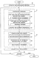
- the initial crack is triangulated in step 10, not necessarily read in flat structure.
- a flat initial crack can be in the form of a simple geometric parameterization specified and automatic be triangulated.
- plane cracks can, for example, two in a straight crack Points on the tear line and one point on the crack surface can be specified.
- Partially circular initial cracks or initial cracks the crack front given by a piecewise quadratic function are specified by specifying a few points.
- the specification of the initial crack is based on empirical values of the user, which for example consists of typical Observations in load tests result.
- the actual crack progress calculation follows. This calculation runs in iterations from which repeated a new cut alternately calculated by the structure, determined a new crack front and the continued crack is triangulated. The determining The new crack front closes the call for a generic one Finite element program, as described in more detail below will be.
- Step 14 the Structure cut with the continued crack.
- This continuation contains the tear. she is so widely expanded that it is at least the smallest the whole Spherical surface enclosing structure reached. This will ensures that the crack continuation is not about inside of the structure ends, but that it is the whole structure completely cuts. This is for the following process steps, especially for the cutting methods used, required.
- step 14 The exact shape of the crack continuation determined in step 14 is of little importance since the direction (and the Amount) of crack development in the following process steps largely based on the finite element calculation is independent of the crack continuation. Therefore are different crack continuation strategies in step 14 possible.
- the embodiment described here serves as Crack continuation of a plane crack simply the crack plane. Is if the crack is not even, the crack continuation is a continuation the triangulation of the crack. To continue this form any concave parts of the outer contour of the crack complemented with triangles until the entire Contour is convex. Then along the additional triangles are generated until the local tangents Expansion of the crack propagation described above is achieved is.
- the crack continuation generated (including the crack it contains) into the (Untorn) structure inserted.
- the type of subdivision is for predefines a set of typical basic topologies. All other possible constellations are determined in advance by suitable ones Divisions traced back to one of these basic topologies, such as this is described in more detail below.
- step 16 runs in three steps. First there are optimizing Modifications to the network defining the structure. The reason for this first step is that the later the finite element methods used are all the more precise, the more cube-like the individual volume elements are. Very long and narrow elements can affect the calculation result distort. Therefore, in the present embodiment individual points of the network structure shifted to such unfavorable element shapes as a result of the following Avoid cuts. In particular, this concerns points which are close to the crack continuation, because here after the Cut through the crack continuation often narrow, unfavorable shaped volume elements are created. In alternative versions this optimization step can be carried out in a different way become or be completely eliminated.
- the second substep of step 16 is only for those Volume elements executed, cut by the crack continuation without a basic topology is present.
- the ones defined in the example described here Base topologies are all characterized in that according to the cut from a volume element a maximum of two pieces arise, and that each edge of the volume element at most is cut once from the crack continuation. In particular in the case of curved crack continuations these conditions are however not necessarily fulfilled.
- a U-shaped crack continuation a single volume element in three Cut parts or one edge of the solid twice penetrate.
- a total of 20-knot volume elements distinguish seven basic topologies. For each of these basic topologies there are predefined division rules that ensure that the parts obtained again have 20-knot volume elements are. In addition, they should be in the form of sample networks defined division rules for their part volume elements produce the most suitable for later finite element calculation. Examples for such division rules in the context of plane cracks are in the contain articles of the inventor already mentioned at the beginning, the content of which is hereby incorporated into the present application becomes.
- step 16 these are now mentioned Division rules on each cut from the crack continuation Solid element applied.
- the volume element is cut according to these division rules, being two or more (typically six to ten) new volume elements made in 20-knot form.
- the crack continuation cuts none of the new volume elements, but runs always along the boundaries between solid elements.
- the crack front in the structure inserted.
- the goal of this step is one further subdivision of the volume elements, which aims to that the crack front along an edge of volume elements (and not across a surface). Similar to the Third step of step 16 already described in step 18, the elements cut from the crack front determined and re-networked.
- Step 18 is based on two basic topologies, which are both "normal" 20-knot volume elements also generate so-called collapsed quarter-point elements.
- Collapsed quarter-point elements are a special form of 20-knot volume elements, where three knots on one Top (at the crack front) collapse and the bases are shifted towards the tip at the edges.
- the collapsed Quarter-point elements serve the linear-elastic Stress and strain singularity at the crack front if possible to model exactly. See the basic topologies also a fine breakdown of the generated networks into the area around the crack front. The number of layers and thus the fineness of the modeling can be set by the user become. This allows the calculation accuracy to be checked and the computing time required. Depending on the value this setting can be made in step 18 from a single Volume element, for example, six to 30 volume elements be generated.
- the network structure obtained becomes one again in step 20 Subjected to control to ensure that the items are acceptable for the finite element calculation. there the Jacobi determinant of the elements is calculated.
- a second function block 22 now follows the iteration, in the new crack front with the simulated cyclical load is determined.
- voltage values on the previous Crack front (crack tip) using a generic finite element program calculated.
- Such programs are in themselves known and therefore do not need to be described here in detail to become. For example, this is suitable under the Trade name “Abaqus" program available.
- the goal of the finite element calculation in step 24 is to determine the stress fields on the crack front and to derive the stress intensity factors (K values) from the asymptotic stress fields on the crack front.
- K values are measures for the speed of crack propagation, whereby three modes (corresponding to the values K I , K II and K III ) are considered. In total, the three K values mentioned are calculated in step 24 for each node of the volume elements on the crack front. This calculation step is known per se.
- the crack propagation law depends on the material and is from User specified. In the embodiment described here a homogeneous material is required. Coatings, which are usually brittle will not considered. Anisotropy of the material can, however be expressed by a suitable crack propagation law. Different crack propagation laws and their basic application for crack progress simulation are well known, so here on the knowledge of the relevant Professional and the basic technical literature are referred can.
- step 28 scale the results of step 26 so that a given one Maximum value for crack propagation just reached becomes.
- the maximum crack propagation along the crack front for a stress cycle A Divide the specified maximum value (e.g. 50 ⁇ m) by gives the maximum crack progress value just calculated the number of stress cycles in the current Iteration can be simulated. This number is simultaneous the multiplication factor for scaling the results in step 28.
- step 30 Basis of the previous crack and the crack increment new crack front determined. This new crack front is also called continued crack called.
- the continued crack which is usually not even, triangulates. While in the embodiment described here it is intended to triangulate the original crack and just a new triangulation of the crack increment is added in execution alternatives completely new triangulation of the continued crack created.
- the iteration can now start again at step 14 (Test 34).
- the crack continues in the next iteration cycle used as initial crack. Is a given Termination criterion met (e.g. depending on the degree of crack propagation or the number of iterations or a user action), the procedure ends.
- the method according to the invention makes predictions over the life of workpieces with cyclic Stress has been achieved which is a surprising match with experimental results.
Landscapes
- Physics & Mathematics (AREA)
- Health & Medical Sciences (AREA)
- Life Sciences & Earth Sciences (AREA)
- Chemical & Material Sciences (AREA)
- Analytical Chemistry (AREA)
- Biochemistry (AREA)
- General Health & Medical Sciences (AREA)
- General Physics & Mathematics (AREA)
- Immunology (AREA)
- Pathology (AREA)
- Investigating Strength Of Materials By Application Of Mechanical Stress (AREA)
- Management, Administration, Business Operations System, And Electronic Commerce (AREA)
- Geophysics And Detection Of Objects (AREA)
Abstract
Description
Claims (9)
- Verfahren zur Rißfortschrittssimulation, mit den Schritten:a) Bereitstellen (10) einer Definition einer dreidimensionalen Struktur und eines Anfangsrisses,b) Berechnen (12) eines Schnitts durch die Struktur entlang einer Rißfortsetzung,c) Bestimmen (22) einer neuen Rißfront, indem Spannungswerte durch eine Finite-Elemente-Berechnung bestimmt werden und ein Rißfortschrittsgesetz angewendet wird,d) Triangulieren (32) des weitergeführten Risses, unde) Wiederholen (34) der Schritte b) bis e), bis eine vorbestimmte Endbedingung erfüllt ist.
- Verfahren nach Anspruch 1,
dadurch gekennzeichnet, daß der Anfangsriß in Schritt a) als triangulierter, nicht notwendigerweise ebener Riß bereitgestellt wird. - Verfahren nach Anspruch 1 oder 2,
dadurch gekennzeichnet, daß in Schritt b) zunächst die Rißfortsetzung erzeugt wird (14) und dann zumindest jedes von der Rißfortsetzung geschnittene Element der Struktur in mindestens zwei Teile aufgespalten wird (16), an deren Grenze die Rißfortsetzung verläuft. - Verfahren nach Anspruch 3,
dadurch gekennzeichnet, daß in Schritt b) ferner zumindest jedes von der Rißfront geschnittene Element der Struktur in mindestens zwei Teile aufgespalten wird (18), an deren Grenzlinien die Rißfront verläuft. - Verfahren nach Anspruch 3 oder 4,
dadurch gekennzeichnet, daß beim Erzeugen (14) der Rißfortsetzung zunächst eine konvexe Rißkontur erzeugt wird und dann an den Rändern der Rißkontur zusätzliche Dreiecke erzeugt werden, bis eine die Struktur vollständig schneidende Triangulierung vorliegt. - Verfahren nach einem der Ansprüche 1 bis 5,
dadurch gekennzeichnet, daß in Schritt c) die Ergebnisse einer Anwendung des Rißfortschrittsgesetzes auf die berechneten Spannungswerte skaliert werden (28), bis eine vorbestimmte Bedingung erreicht ist. - Verfahren nach einem der Ansprüche 1 bis 5,
dadurch gekennzeichnet, daß in Schritt c) das Rißfortschrittsgesetz auf Grundlage der einmal berechneten Spannungswerte wiederholt angewandt wird, bis eine vorbestimmte Bedingung erreicht ist. - Verfahren nach Anspruch 6 oder Anspruch 7,
dadurch gekennzeichnet, daß die vorbestimmte Bedingung das Erreichen eines Rißfortschritts-Maximalwertes ist. - Verfahren nach einem der Ansprüche 1 bis 8,
dadurch gekennzeichnet, daß in Schritt d) die Triangulierung des bisherigen Risses beibehalten und nur das Rißinkrement neu trianguliert wird (32).
Applications Claiming Priority (2)
| Application Number | Priority Date | Filing Date | Title |
|---|---|---|---|
| DE19927941A DE19927941C1 (de) | 1999-06-20 | 1999-06-20 | Verfahren zur Rißfortschrittssimulation |
| DE19927941 | 1999-06-20 |
Publications (2)
| Publication Number | Publication Date |
|---|---|
| EP1065493A1 true EP1065493A1 (de) | 2001-01-03 |
| EP1065493B1 EP1065493B1 (de) | 2008-10-29 |
Family
ID=7911742
Family Applications (1)
| Application Number | Title | Priority Date | Filing Date |
|---|---|---|---|
| EP00109835A Expired - Lifetime EP1065493B1 (de) | 1999-06-20 | 2000-05-10 | Verfahren zur Rissfortschrittssimulation |
Country Status (6)
| Country | Link |
|---|---|
| US (1) | US6813592B1 (de) |
| EP (1) | EP1065493B1 (de) |
| JP (1) | JP2001034655A (de) |
| AT (1) | ATE412885T1 (de) |
| DE (2) | DE19927941C1 (de) |
| ES (1) | ES2312313T3 (de) |
Cited By (1)
| Publication number | Priority date | Publication date | Assignee | Title |
|---|---|---|---|---|
| CN108921950A (zh) * | 2018-06-28 | 2018-11-30 | 郑州云海信息技术有限公司 | 三维裂缝模拟的方法以及相关装置 |
Families Citing this family (19)
| Publication number | Priority date | Publication date | Assignee | Title |
|---|---|---|---|---|
| DE10208144B4 (de) * | 2001-03-07 | 2012-01-26 | Steyr-Daimler-Puch Fahrzeugtechnik Ag & Co. Kg | Verfahren zur Berechnung der Lebensdauer nichtproportional beanspruchter Bauteile |
| JP3886865B2 (ja) * | 2001-11-09 | 2007-02-28 | 三菱重工業株式会社 | 金属材料の損傷評価方法及び装置 |
| US7469200B2 (en) * | 2003-05-14 | 2008-12-23 | Ford Global Technologies, Llc | Method and apparatus for predicting belt separation failure in aging tires by computer simulation |
| DE10352720A1 (de) | 2003-11-12 | 2005-06-30 | Daimlerchrysler Ag | Finite-Elemente-Simulation |
| US7467070B2 (en) * | 2004-10-26 | 2008-12-16 | Meyer Eric S | Methods and systems for modeling stress intensity solutions for integrally stiffened panels |
| JP4329848B2 (ja) | 2007-06-15 | 2009-09-09 | トヨタ自動車株式会社 | 構造解析装置および構造解析方法 |
| US20110010140A1 (en) * | 2009-07-13 | 2011-01-13 | Northrop Grumman Corporation | Probability Distribution Function Mapping Method |
| US8494827B2 (en) * | 2009-09-25 | 2013-07-23 | Exxonmobil Upstream Research Company | Method of predicting natural fractures and damage in a subsurface region |
| DE102010012564B4 (de) * | 2010-03-23 | 2012-04-05 | Mtu Aero Engines Gmbh | Verfahren und Vorrichtung zur Ermittlung einer Materialantwort bei einem Bauteil |
| US8576225B2 (en) | 2010-06-30 | 2013-11-05 | Dreamworks Animation Llc | Seamless fracture in a production pipeline |
| US9103741B2 (en) | 2010-08-27 | 2015-08-11 | General Electric Company | Methods and systems for assessing residual life of turbomachine airfoils |
| US9235902B2 (en) | 2011-08-04 | 2016-01-12 | University Of Southern California | Image-based crack quantification |
| FR2981155B1 (fr) * | 2011-10-11 | 2014-03-28 | Snecma | Procede de simulation numerique et de validation experimentale de la propagation de fissures dans une piece metallique |
| WO2013090830A1 (en) * | 2011-12-16 | 2013-06-20 | University Of Southern California | Autonomous pavement condition assessment |
| DE102014218132A1 (de) * | 2014-09-10 | 2016-03-10 | Fraunhofer-Gesellschaft zur Förderung der angewandten Forschung e.V. | Verfahren und Vorrichtung zur Bestimmung einer Qualität eines Bauteils |
| CN104374556A (zh) * | 2014-11-10 | 2015-02-25 | 上海交通大学 | 导管架监测方法 |
| CN114970260B (zh) * | 2022-05-20 | 2024-04-02 | 武汉大学 | 一种用于模拟复合材料破坏的格构相场方法 |
| CN115391853A (zh) * | 2022-08-30 | 2022-11-25 | 浙江大学 | 一种轮胎裂纹路径的预测方法及装置 |
| CN117272768B (zh) * | 2023-09-18 | 2024-07-02 | 中南大学 | 一种裂纹扩展模拟方法和装置 |
Citations (1)
| Publication number | Priority date | Publication date | Assignee | Title |
|---|---|---|---|---|
| US5731817A (en) * | 1995-10-11 | 1998-03-24 | Motorola, Inc. | Method and apparatus for generating a hexahedron mesh of a modeled structure |
Family Cites Families (4)
| Publication number | Priority date | Publication date | Assignee | Title |
|---|---|---|---|---|
| WO1994008912A2 (en) * | 1992-10-13 | 1994-04-28 | Ushers Inc. | Improved aggregates, and apparatus and method for making same |
| US6128577A (en) * | 1996-12-19 | 2000-10-03 | Schlumberger Technology Corporation | Modeling geological structures and properties |
| US5826213A (en) * | 1997-02-25 | 1998-10-20 | Kennefick; Christine | Method and apparatus for investigating toughening mechanisms and crack advance in lightweight materials |
| US6456289B1 (en) * | 1999-04-23 | 2002-09-24 | Georgia Tech Research Corporation | Animation system and method for a animating object fracture |
-
1999
- 1999-06-20 DE DE19927941A patent/DE19927941C1/de not_active Expired - Fee Related
-
2000
- 2000-05-10 DE DE50015417T patent/DE50015417D1/de not_active Expired - Lifetime
- 2000-05-10 ES ES00109835T patent/ES2312313T3/es not_active Expired - Lifetime
- 2000-05-10 EP EP00109835A patent/EP1065493B1/de not_active Expired - Lifetime
- 2000-05-10 AT AT00109835T patent/ATE412885T1/de not_active IP Right Cessation
- 2000-06-20 JP JP2000184616A patent/JP2001034655A/ja not_active Withdrawn
- 2000-06-20 US US09/597,471 patent/US6813592B1/en not_active Expired - Fee Related
Patent Citations (1)
| Publication number | Priority date | Publication date | Assignee | Title |
|---|---|---|---|---|
| US5731817A (en) * | 1995-10-11 | 1998-03-24 | Motorola, Inc. | Method and apparatus for generating a hexahedron mesh of a modeled structure |
Non-Patent Citations (5)
| Title |
|---|
| DE ARAUJO, T. D. P.; CALVACANTE NETO, J. B.; DE CARVALHO, M. T. M.; BITTENCOURT, T. N.; MARTHA, L. F.: "Adaptive Simulation of Fracture Processes Based on Spatial Enumeration Techniques", INTERNATIONAL JOURNAL OF ROCK MECHANICS AND MINING SCIENCES, vol. 34, no. 3/4, 1997, pages 551, XP000942719 * |
| DHONDT G: "AUTOMATIC 3-D MODE I CRACK PROPAGATION CALCULATIONS WITH FINITE ELEMENTS", INTERNATIONAL JOURNAL OF NUMERICAL METHODS IN ENGINEERING,GB,CHICHESTER, vol. 41, no. 4, 28 February 1998 (1998-02-28), pages 739 - 757, XP000866379, ISSN: 0029-5981 * |
| DHONDT G: "CUTTING OF A 3-D FINITE ELEMENT MESH FOR AUTOMATIC MODE I CRACK PROPAGATION CALCULATIONS", INTERNATIONAL JOURNAL OF NUMERICAL METHODS IN ENGINEERING,GB,CHICHESTER, vol. 42, no. 4, 30 June 1998 (1998-06-30), pages 749 - 772, XP000866390, ISSN: 0029-5981 * |
| KRYSL, P., BELYTSCHKO, T.: "The Element Free Garlekin Method for Dynamic Propagation of Arbitrary 3-D Cracks", INTERNATIONAL JOURNAL FOR NUMERICAL METHODS IN ENGINEERING, vol. 44, no. 6, 28 February 1999 (1999-02-28), pages 767 - 800, XP000942717 * |
| LEWICKI, D.G., BALLARINI, R.: "Effect of Rim Thickness on Gear Crack Propagation Path", TRANSACTIONS OF THE ASME, vol. 119, no. 1, 1997, pages 88 - 95, XP000942713 * |
Cited By (2)
| Publication number | Priority date | Publication date | Assignee | Title |
|---|---|---|---|---|
| CN108921950A (zh) * | 2018-06-28 | 2018-11-30 | 郑州云海信息技术有限公司 | 三维裂缝模拟的方法以及相关装置 |
| CN108921950B (zh) * | 2018-06-28 | 2022-03-22 | 郑州云海信息技术有限公司 | 三维裂缝模拟的方法以及相关装置 |
Also Published As
| Publication number | Publication date |
|---|---|
| JP2001034655A (ja) | 2001-02-09 |
| ATE412885T1 (de) | 2008-11-15 |
| EP1065493B1 (de) | 2008-10-29 |
| DE19927941C1 (de) | 2000-12-14 |
| US6813592B1 (en) | 2004-11-02 |
| ES2312313T3 (es) | 2009-03-01 |
| DE50015417D1 (de) | 2008-12-11 |
Similar Documents
| Publication | Publication Date | Title |
|---|---|---|
| DE19927941C1 (de) | Verfahren zur Rißfortschrittssimulation | |
| DE102007021753A1 (de) | System und Verfahren zum Analysieren von Modellierungsgenauigkeit während einer Durchführung von reverser Konstruktion mit 3D-Abtastdaten | |
| DE102007021697A1 (de) | System und Verfahren für Gitter- und Körperhybridmodellierung unter Benutzung von 3D-Abtastdaten | |
| EP3592561B1 (de) | Verfahren zur additiven fertigung eines dreidimensionalen gegenstandes | |
| EP1665103A1 (de) | Bestimmung eines modells einer geometrie einer blech-umformstufe | |
| DE112011101166B4 (de) | System und Verfahren zum Optimieren einer Bearbeitungssimulation | |
| EP3170648B1 (de) | Additives herstellungsverfahren und verfahren zur ansteuerung einer vorrichtung zur additiven herstellung eines dreidimensionalen bauteils | |
| EP1334468B1 (de) | Verfahren und system zur rekonstruktion einer fläche | |
| DE102015120118A1 (de) | Werkzeugwegkurvenerzeugungsverfahren und Werkzeugwegkurvenerzeugungsvorrichtung | |
| DE3887422T2 (de) | Verfahren zum eintragen von informationen über das profil eines gegenstandes. | |
| DE69829844T2 (de) | Verfahren zum modellieren von dreidimensionalen objekten und simulation von flüssigkeitsströmung | |
| DE112014002120T5 (de) | System und Verfahren zur Durchführung von Operationen zum Rückgängigmachen und Wiederherstellen während der Bearbeitungssimulation | |
| EP1741012B1 (de) | Bestimmung von prozess-operationen zur beschreibung von umformprozessen an einem umformteil | |
| DE10145515B4 (de) | Optimierung der Parametrierung einer Werkzeugmaschine | |
| DE112004000199T5 (de) | Verfahren zum Abschätzen der Beziehung zwischen der Elementenverzerrung und dem Analyseverfahren | |
| DE102015214750A1 (de) | Verfahren und Vorrichtung zur Form- und Topologieoptimierung eines Gussbauteils | |
| WO2023279125A1 (de) | Verfahren zum erstellen von simulationszellen für kontinuumsmechanische simulationen eines objekts | |
| EP0986027B1 (de) | Verfahren zur Generierung eines Finite-Elemente-Modells einer Formschale für ein Gussteil | |
| Mayer et al. | Ermittlung eines Skelettierungsverfahrens zur Konvertierung von Topologieoptimierungsergebnissen | |
| EP3884347A1 (de) | Kollisionsprüfung auf basis höherwertiger geometrie | |
| DE10054723A1 (de) | Anordnung und Verfahren zur Überprüfung der Bearbeitungsdurchführbarkeit | |
| DE60309298T2 (de) | Verfahren und anordnung zur automatischen einstellung von einrichtungen mit einstellelementen und entsprechendes computerprogrammprodukt und entsprechendes computerlesbares speichermedium | |
| DE102014015088A1 (de) | Verfahren zur Ermittlung einer Düsenpositionierung für die Herstellung eines Kunststoff-Spritzgussbauteils, und Verfahren zur Herstellung eines Kunststoff-Spritzgussbauteils | |
| EP3547264B1 (de) | Verfahren zur erzeugung einer stricktechnisch herstellbaren abwicklung einer oberfläche eines dreidimensionalen körpers | |
| DE3889321T2 (de) | Verfahren zur vorbereitung von numerisch gesteuerten daten zum schneiden von rillen. |
Legal Events
| Date | Code | Title | Description |
|---|---|---|---|
| PUAI | Public reference made under article 153(3) epc to a published international application that has entered the european phase |
Free format text: ORIGINAL CODE: 0009012 |
|
| AK | Designated contracting states |
Kind code of ref document: A1 Designated state(s): AT BE CH CY DE DK ES FI FR GB GR IE IT LI LU MC NL PT SE |
|
| AX | Request for extension of the european patent |
Free format text: AL;LT;LV;MK;RO;SI |
|
| RAP1 | Party data changed (applicant data changed or rights of an application transferred) |
Owner name: MTU AERO ENGINES GMBH |
|
| 17P | Request for examination filed |
Effective date: 20010208 |
|
| AKX | Designation fees paid |
Free format text: AT BE CH CY DE DK ES FI FR GB GR IE IT LI LU MC NL PT SE |
|
| 17Q | First examination report despatched |
Effective date: 20071227 |
|
| GRAP | Despatch of communication of intention to grant a patent |
Free format text: ORIGINAL CODE: EPIDOSNIGR1 |
|
| GRAS | Grant fee paid |
Free format text: ORIGINAL CODE: EPIDOSNIGR3 |
|
| GRAA | (expected) grant |
Free format text: ORIGINAL CODE: 0009210 |
|
| AK | Designated contracting states |
Kind code of ref document: B1 Designated state(s): AT BE CH CY DE DK ES FI FR GB GR IE IT LI LU MC NL PT SE |
|
| REG | Reference to a national code |
Ref country code: GB Ref legal event code: FG4D Free format text: NOT ENGLISH |
|
| REG | Reference to a national code |
Ref country code: CH Ref legal event code: NV Representative=s name: ISLER & PEDRAZZINI AG Ref country code: CH Ref legal event code: EP |
|
| REG | Reference to a national code |
Ref country code: IE Ref legal event code: FG4D Free format text: LANGUAGE OF EP DOCUMENT: GERMAN |
|
| REF | Corresponds to: |
Ref document number: 50015417 Country of ref document: DE Date of ref document: 20081211 Kind code of ref document: P |
|
| REG | Reference to a national code |
Ref country code: SE Ref legal event code: TRGR |
|
| REG | Reference to a national code |
Ref country code: ES Ref legal event code: FG2A Ref document number: 2312313 Country of ref document: ES Kind code of ref document: T3 |
|
| NLV1 | Nl: lapsed or annulled due to failure to fulfill the requirements of art. 29p and 29m of the patents act | ||
| PG25 | Lapsed in a contracting state [announced via postgrant information from national office to epo] |
Ref country code: PT Free format text: LAPSE BECAUSE OF FAILURE TO SUBMIT A TRANSLATION OF THE DESCRIPTION OR TO PAY THE FEE WITHIN THE PRESCRIBED TIME-LIMIT Effective date: 20090330 Ref country code: NL Free format text: LAPSE BECAUSE OF FAILURE TO SUBMIT A TRANSLATION OF THE DESCRIPTION OR TO PAY THE FEE WITHIN THE PRESCRIBED TIME-LIMIT Effective date: 20081029 Ref country code: FI Free format text: LAPSE BECAUSE OF FAILURE TO SUBMIT A TRANSLATION OF THE DESCRIPTION OR TO PAY THE FEE WITHIN THE PRESCRIBED TIME-LIMIT Effective date: 20081029 |
|
| REG | Reference to a national code |
Ref country code: IE Ref legal event code: FD4D |
|
| PG25 | Lapsed in a contracting state [announced via postgrant information from national office to epo] |
Ref country code: DK Free format text: LAPSE BECAUSE OF FAILURE TO SUBMIT A TRANSLATION OF THE DESCRIPTION OR TO PAY THE FEE WITHIN THE PRESCRIBED TIME-LIMIT Effective date: 20081029 Ref country code: IE Free format text: LAPSE BECAUSE OF FAILURE TO SUBMIT A TRANSLATION OF THE DESCRIPTION OR TO PAY THE FEE WITHIN THE PRESCRIBED TIME-LIMIT Effective date: 20081029 |
|
| PLBE | No opposition filed within time limit |
Free format text: ORIGINAL CODE: 0009261 |
|
| STAA | Information on the status of an ep patent application or granted ep patent |
Free format text: STATUS: NO OPPOSITION FILED WITHIN TIME LIMIT |
|
| 26N | No opposition filed |
Effective date: 20090730 |
|
| BERE | Be: lapsed |
Owner name: MTU AERO ENGINES G.M.B.H. Effective date: 20090531 |
|
| PG25 | Lapsed in a contracting state [announced via postgrant information from national office to epo] |
Ref country code: MC Free format text: LAPSE BECAUSE OF NON-PAYMENT OF DUE FEES Effective date: 20090531 |
|
| PG25 | Lapsed in a contracting state [announced via postgrant information from national office to epo] |
Ref country code: BE Free format text: LAPSE BECAUSE OF NON-PAYMENT OF DUE FEES Effective date: 20090531 |
|
| PG25 | Lapsed in a contracting state [announced via postgrant information from national office to epo] |
Ref country code: AT Free format text: LAPSE BECAUSE OF NON-PAYMENT OF DUE FEES Effective date: 20090510 |
|
| PG25 | Lapsed in a contracting state [announced via postgrant information from national office to epo] |
Ref country code: GR Free format text: LAPSE BECAUSE OF FAILURE TO SUBMIT A TRANSLATION OF THE DESCRIPTION OR TO PAY THE FEE WITHIN THE PRESCRIBED TIME-LIMIT Effective date: 20090130 |
|
| PG25 | Lapsed in a contracting state [announced via postgrant information from national office to epo] |
Ref country code: LU Free format text: LAPSE BECAUSE OF NON-PAYMENT OF DUE FEES Effective date: 20090510 |
|
| PG25 | Lapsed in a contracting state [announced via postgrant information from national office to epo] |
Ref country code: CY Free format text: LAPSE BECAUSE OF FAILURE TO SUBMIT A TRANSLATION OF THE DESCRIPTION OR TO PAY THE FEE WITHIN THE PRESCRIBED TIME-LIMIT Effective date: 20081029 |
|
| PGFP | Annual fee paid to national office [announced via postgrant information from national office to epo] |
Ref country code: ES Payment date: 20120521 Year of fee payment: 13 |
|
| PGFP | Annual fee paid to national office [announced via postgrant information from national office to epo] |
Ref country code: CH Payment date: 20130522 Year of fee payment: 14 Ref country code: SE Payment date: 20130521 Year of fee payment: 14 Ref country code: DE Payment date: 20130522 Year of fee payment: 14 Ref country code: GB Payment date: 20130522 Year of fee payment: 14 |
|
| PGFP | Annual fee paid to national office [announced via postgrant information from national office to epo] |
Ref country code: IT Payment date: 20130525 Year of fee payment: 14 Ref country code: FR Payment date: 20130604 Year of fee payment: 14 |
|
| REG | Reference to a national code |
Ref country code: DE Ref legal event code: R119 Ref document number: 50015417 Country of ref document: DE |
|
| REG | Reference to a national code |
Ref country code: CH Ref legal event code: PL |
|
| GBPC | Gb: european patent ceased through non-payment of renewal fee |
Effective date: 20140510 |
|
| PG25 | Lapsed in a contracting state [announced via postgrant information from national office to epo] |
Ref country code: SE Free format text: LAPSE BECAUSE OF NON-PAYMENT OF DUE FEES Effective date: 20140511 Ref country code: CH Free format text: LAPSE BECAUSE OF NON-PAYMENT OF DUE FEES Effective date: 20140531 Ref country code: LI Free format text: LAPSE BECAUSE OF NON-PAYMENT OF DUE FEES Effective date: 20140531 |
|
| REG | Reference to a national code |
Ref country code: SE Ref legal event code: EUG |
|
| REG | Reference to a national code |
Ref country code: DE Ref legal event code: R119 Ref document number: 50015417 Country of ref document: DE Effective date: 20141202 |
|
| REG | Reference to a national code |
Ref country code: FR Ref legal event code: ST Effective date: 20150130 |
|
| PG25 | Lapsed in a contracting state [announced via postgrant information from national office to epo] |
Ref country code: IT Free format text: LAPSE BECAUSE OF NON-PAYMENT OF DUE FEES Effective date: 20140510 Ref country code: DE Free format text: LAPSE BECAUSE OF NON-PAYMENT OF DUE FEES Effective date: 20141202 |
|
| PG25 | Lapsed in a contracting state [announced via postgrant information from national office to epo] |
Ref country code: FR Free format text: LAPSE BECAUSE OF NON-PAYMENT OF DUE FEES Effective date: 20140602 Ref country code: GB Free format text: LAPSE BECAUSE OF NON-PAYMENT OF DUE FEES Effective date: 20140510 |
|
| REG | Reference to a national code |
Ref country code: ES Ref legal event code: FD2A Effective date: 20150626 |
|
| PG25 | Lapsed in a contracting state [announced via postgrant information from national office to epo] |
Ref country code: ES Free format text: LAPSE BECAUSE OF NON-PAYMENT OF DUE FEES Effective date: 20140511 |