EP1065005A2 - Device for feeding liquid - Google Patents
Device for feeding liquid Download PDFInfo
- Publication number
- EP1065005A2 EP1065005A2 EP00107815A EP00107815A EP1065005A2 EP 1065005 A2 EP1065005 A2 EP 1065005A2 EP 00107815 A EP00107815 A EP 00107815A EP 00107815 A EP00107815 A EP 00107815A EP 1065005 A2 EP1065005 A2 EP 1065005A2
- Authority
- EP
- European Patent Office
- Prior art keywords
- container
- liquid
- supply device
- liquid supply
- collapsible
- Prior art date
- Legal status (The legal status is an assumption and is not a legal conclusion. Google has not performed a legal analysis and makes no representation as to the accuracy of the status listed.)
- Withdrawn
Links
Images

Classifications
-
- B—PERFORMING OPERATIONS; TRANSPORTING
- B05—SPRAYING OR ATOMISING IN GENERAL; APPLYING FLUENT MATERIALS TO SURFACES, IN GENERAL
- B05C—APPARATUS FOR APPLYING FLUENT MATERIALS TO SURFACES, IN GENERAL
- B05C11/00—Component parts, details or accessories not specifically provided for in groups B05C1/00 - B05C9/00
- B05C11/10—Storage, supply or control of liquid or other fluent material; Recovery of excess liquid or other fluent material
Definitions
- the invention relates to a liquid supply device for supply of machines with a liquid from a container according to the preamble of claim 1.
- Liquids such as especially glue, paint and varnish as well as organic Detergents must be kept liquid-tight so that they do not can dry out and react with oxygen, their volatile components cannot evaporate and no bacterial cultures develop in them can.
- Such liquids are usually made in containers Plastic or metal kept. If the liquid from such Container is pumped out with a pressure pump, air is in the container pressed. This allows the liquid to react with the oxygen in the air volatile components can escape from the liquid, and the Conveying speed is limited because the containers have high air pressures Do not stand the pressure pump unless there are containers made of very thick Plastic material or metal used. The use of containers with thick plastic walls or metal is expensive to manufacture and very expensive expensive to dispose of (sometimes as hazardous waste) or in the recycling process and the containers are heavy. Due to the limited pressure resistance the container is also the delivery pressure of the pressure pump and thus the Fluid delivery speed limited. This limitation has one Limitation of the production speed of the liquid supplied Machine result.
- a preferred application of the invention relates to glue machines which a container, e.g. Canister, glue fed for application to finished paper to glue sheets of paper or paper webs together.
- a container e.g. Canister
- Paper can also be sheets in the form of sheets (sheets) or endless webs made of plastic, metal, cork or another material.
- the machine is a coating machine for coating a substrate with a Coating material.
- the carrier material is preferably paper in the form of Sheets of paper or webs of paper. Sheets can also be in the form of sheets or Sheets of plastic, metal, cork or other material coated become.
- the coating material is preferably paint or lacquer.
- Another preferred area of application of the invention is machinery or Devices for moistening finished paper to a desired one Reach moisture content and at a predetermined value or Keep value range, e.g. with so-called softening liquid, which is water can be to make paper easier to fold so that it is not in folders tears.
- Softening liquid is especially a commercially available folding aid concentrate, which is a mixture of water and additives e.g. Vinegar and / or dish soap
- Offset printing machines use so-called Fountain solution to form ink-repellent areas on one Printing plate cylinder.
- the fountain solution consists of water, alcohol or Alcohol substitute and so-called additives.
- These liquid additives can according to the invention from an airtight storage container to one Fountain solution preparation tub of the printing press can be conveyed without that the additive comes into contact with air. This prevents organic additive is infested with bacteria or fungi or with Oxygen can react.
- the liquid is pumped from the Container pushed out. This has the disadvantage that if the delivery pressure is too high there is a risk that the container will burst. There is also a risk that the Compressed air from the pressure pump reacts chemically with the liquid or is in the Liquid bacteria or fungi can develop. It is also known Suck the liquid out of a dimensionally stable canister using suction pumps.
- the object of the invention is to achieve a possibility of through which arbitrarily large quantities of liquid are conveyed out of the container material costs, weight and costs for the container and its disposal or recycling can be reduced can, as well as contact of the liquid in the container with air or other Gases can be avoided.
- the walls of the container are designed in such a way that the suction force of the Suction pump, which is required to convey the liquid, bendable and can be moved against each other without the suction force of the suction pump needs to be much higher than for sucking the liquid out of one open container.
- the container walls can be dimensionally unstable, but none or have such a low bending stiffness that they are slightly flexible and could not stand upright on their own without bending, kinking or in fold up.
- the walls of the Container is dimensionally stable, but already due to a low suction power Suction pump plastically deformable. This means that the container walls after the plastic deformation when the deformation forces decrease their deformed Maintain shape.
- glue machines Coating machines and printing machines.
- glue machines and Coating machines apply the liquid to a carrier in the form of finished paper or foil applied, the foil made of metal, plastic or Cork or other material can exist.
- the liquid is a Dampening liquid, e.g. Water, for moistening finished paper, with it it can then be folded or folded more easily in a folder, without tearing the paper.
- a Dampening liquid e.g. Water
- the invention can be used for offset printing presses to make liquid To feed additives from a collapsible container to a mixing container, in which the additive with water and alcohol or alcohol substitute is mixed to form dampening water, which one Printing plate cylinder is supplied to form ink-repellent areas.
- the fountain solution can also be fed to cylinders or rollers of the printing press such as paper guide rollers and chill rollers to prevent contamination, e.g. also to prevent or remove ink deposits.
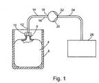
- FIG. 1 shows a container which can be collapsed by the suction force of a suction pump 20 4 in an outer container 6 which supports it laterally and made of non-collapsible stiff material.
- the collapsible container 4 has a neck 8 with a thread on which by means of a threaded sleeve 10 the end 12 of a fluid line 14 is airtight connectable, the other end 16 to the suction side 18 one Suction pump 20 can be connected.
- the pressure side 22 of the suction pump 20 is connected via a further fluid line 24 connected to a machine 26 which dispenses liquid from the suction pump 20 the container 4 can be fed.
- the container 4 is designed to be collapsible in such a way that it passes through the subatmospheric pressure of the suction pump 20 is easily collapsible and corresponding to the amount of liquid drawn from it and collapses the suction power of the suction pump 20 offers only very little resistance.
- the walls of the container 4 can be very dimensionally unstable so that they do not or only have low bending stiffness and do not stand upright on their own without bending, kinking or collapsing.
- the walls of the container 4 Dimensionally stable, but with extremely little force, which is due to the conveying suction force the suction pump 20 is applied, easily plastically deformable.
- This easy plastic deformability has the consequence that when the suction power decreases the suction pump 20 the container 4 maintains its deformed shape.
- the container 4 in one to accommodate dimensionally stable outer container 6, from whose side walls he on old pages is supported.
- the outer container 6 not only makes it easier Transport of the dimensionally unstable container 4, but also prevents Damage to him.
- the container 4 consists of flexible plastic or rubber.
- Such containers are simple and inexpensive to manufacture very thin-walled, e.g. by thin from a foil-like Plastic tubing hose sections cut off at both ends be welded shut. During the welding process, at the same time a hose end a line connection are formed, which in the Figures 1, 2 and 3 in the form of the neck 8 is shown symbolically.
- the end 12 of the suction fluid line 14 to be connected to the container 4 can be designed as a puncture tube 28 or be provided with such a puncture tube 28 for piercing a container closure 30 on the neck 8.
- the Container closure 30 can be a film welded onto the neck 8 or through the container 4 itself be formed.
- the puncture tube 28 can without the Threaded sleeve 10 are used or be designed so that they Screw the threaded sleeve 10 to the neck 8 through the container closure 30 is inserted automatically.
- the suction fluid line 14 is a lancing element in the form of a knife-like or have needle-like tip, which has no liquid passage opening.
- the end 12 the suction fluid line 14 in the neck 8 or at least through the threaded sleeve 10 protrude or be fluidly connected thereto.
- the container 4 need not have a neck 8, but rather that through the neck 8 formed line connection of the container 4 can also by a flat or be formed differently shaped container wall of the container 4, which the Cover wall, a bottom wall or a side wall of the container 4 can be.
- the machine 26 can be of any of the types mentioned.
- Figure 3 shows an example of a glue machine 26, in which glue from the Container 4 on one or both tracks 32 and 34, e.g. Paper webs, is applied, which are glued together by the glue.
- glue machines and also the other types of machines are in practice are known and are therefore not described in detail.
- the container 4 is designed such that it corresponds approximately to the continuously sucked from him by the suction pump 20 amount of liquid collapsed.
- the collapse of the container 4 follows substantially continuously Fluid withdrawal.
- the collapsible container 4 is preferably in the form of a flexible bag.
- the capacity of the collapsible container 4 is at least 1 liter (1 cubic decimeter).
Abstract
Description
Die Erfindung betrifft eine Flüssigkeits-Versorgungsvorrichtung zur Versorgung von Maschinen mit einer Flüssigkeit aus einem Behälter gemäß dem Oberbegriff von Anspruch 1.The invention relates to a liquid supply device for supply of machines with a liquid from a container according to the preamble of claim 1.
Flüssigkeiten wie insbesondere Leim, Farbe und Lack sowie organische Waschmittel müssen flüssigkeitsdicht aufbewahrt werden, damit sie nicht austrocknen und mit Sauerstoff reagieren können, ihre flüchtigen Bestandteile nicht verdunsten können, und sich in ihnen keine Bakterienkulturen entwickeln können.Liquids such as especially glue, paint and varnish as well as organic Detergents must be kept liquid-tight so that they do not can dry out and react with oxygen, their volatile components cannot evaporate and no bacterial cultures develop in them can.
Solche Flüssigkeiten werden üblicherweise in Behältern bzw.Kanistern aus Kunststoff oder Metall aufbewahrt. Wenn die Flüssigkeit aus einem solchen Behälter mit einer Druckpumpe herausgefördert wird, wird Luft in den Behälter gepreßt. Dadurch kann die Flüssigkeit mit dem Sauerstoff der Luft reagieren, flüchtige Bestandteile können aus der Flüssigkeit entweichen, und die Fördergeschwindigkeit ist begrenzt, weil die Behälter hohe Luftdrücke der Druckpumpe nicht aushalten, außer es werden Behälter aus sehr dickem Kunststoffmaterial oder Metall verwendet. Die Verwendung von Behältern mit dicken Kunststoffwänden oder aus Metall ist teuer in der Herstellung und sehr teuer in der Entsorgung (manchmal als Sondermüll) oder im Recyclingverfahren und die Behälter haben ein hohes Gewicht. Durch die begrenzte Druckfestigkeit der Behälter ist auch der Förderdruck der Druckpumpe und damit die Fördergeschwindigkeit der Flüssigkeit begrenzt. Diese Begrenzung hat eine Beschränkung der Produktionsgeschwindigkeit der mit der Flüssigkeit versorgten Maschine zur Folge.Such liquids are usually made in containers Plastic or metal kept. If the liquid from such Container is pumped out with a pressure pump, air is in the container pressed. This allows the liquid to react with the oxygen in the air volatile components can escape from the liquid, and the Conveying speed is limited because the containers have high air pressures Do not stand the pressure pump unless there are containers made of very thick Plastic material or metal used. The use of containers with thick plastic walls or metal is expensive to manufacture and very expensive expensive to dispose of (sometimes as hazardous waste) or in the recycling process and the containers are heavy. Due to the limited pressure resistance the container is also the delivery pressure of the pressure pump and thus the Fluid delivery speed limited. This limitation has one Limitation of the production speed of the liquid supplied Machine result.
Eine bevorzugte Anwendung der Erfindung betrifft Leimmaschinen, welchen aus einem Behälter, z.B. Kanister, Leim zum Auftragen auf fertiges Papier zugeführt wird, um Papierbögen oder Papierbahnen zusammenzukleben. Anstelle von Papier können auch Folien in Form von Bögen (Blätter) oder endlosen Bahnen aus Kunststoff, Metall, Kork oder einem anderen Material verwendet werden.A preferred application of the invention relates to glue machines which a container, e.g. Canister, glue fed for application to finished paper to glue sheets of paper or paper webs together. Instead of Paper can also be sheets in the form of sheets (sheets) or endless webs made of plastic, metal, cork or another material.
Gemäß einer anderen bevorzugten Anwendung der Erfindung ist die Maschine eine Beschichtungsmaschine zum Beschichten von Trägermaterial mit einem Beschichtungsmaterial. Das Trägermaterial ist vorzugsweise Papier in Form von Papierbögen oder Papierbahnen. Auch können Folien in Form von Bögen oder Bahnen aus Kunststoff, Metall, Kork oder aus einem anderen Material beschichtet werden. Das Beschichtungsmaterial ist vorzugsweise Farbe oder Lack.According to another preferred application of the invention, the machine is a coating machine for coating a substrate with a Coating material. The carrier material is preferably paper in the form of Sheets of paper or webs of paper. Sheets can also be in the form of sheets or Sheets of plastic, metal, cork or other material coated become. The coating material is preferably paint or lacquer.
Ein weiteres bevorzugtes Anwendungsgebiet der Erfindung sind Maschinen oder Vorrichtungen zum Befeuchten von fertigem Papier, um einen gewünschten Feuchtigkeitsgehalt zu erreichen und auf einem vorbestimmten Wert oder Wertebereich zu halten, z.B. mit sogenannter Softening-Flüssigkeit, was Wasser sein kann, um Papier leichter faltbar zu machen, damit es in Falzapparaten nicht reißt. Softening-Flüssigkeit ist insbesondere handelsübliches Falzhilfekonzentrat, was eine Mischung aus Wasser und Zusätzen z.B. Essig und/ oder Spülmittel istAnother preferred area of application of the invention is machinery or Devices for moistening finished paper to a desired one Reach moisture content and at a predetermined value or Keep value range, e.g. with so-called softening liquid, which is water can be to make paper easier to fold so that it is not in folders tears. Softening liquid is especially a commercially available folding aid concentrate, which is a mixture of water and additives e.g. Vinegar and / or dish soap
Ein weiteres bevorzugtes Anwendungsgebiet der Erfindung sind Druckmaschinen in Form von Bogendruckmaschinen und Rollendruckmaschinen, insbesondere Offset-Druckmaschinen. Offset-Druckmaschinen verwenden sogenanntes Feuchtwasser zur Bildung von farbabstoßenden Bereichen auf einem Druckplattenzylinder. Das Feuchtwasser besteht aus Wasser, Alkohol oder Alkoholersatzstoff und sogenannten Zusätzen. Diese flüssigen Zusätze können gemäß der Erfindung aus einem luftdichten Vorrats-Behälter zu einer Feuchtwasser-Zubereitungswanne der Druckmaschine gefördert werden, ohne daß das Zusatzmittel mit Luft in Berührung kommt. Dadurch wird verhindert, daß organisches Zusatzmittel von Bakterien oder Pilzen befallen wird oder mit Sauerstoff reagieren kann.Another preferred field of application of the invention is printing machines in the form of sheet-fed printing machines and web printing machines, in particular Offset printing machines. Offset printing machines use so-called Fountain solution to form ink-repellent areas on one Printing plate cylinder. The fountain solution consists of water, alcohol or Alcohol substitute and so-called additives. These liquid additives can according to the invention from an airtight storage container to one Fountain solution preparation tub of the printing press can be conveyed without that the additive comes into contact with air. This prevents organic additive is infested with bacteria or fungi or with Oxygen can react.
Beim Stand der Technik wird die Flüssigkeit durch Druckpumpen aus dem Behälter herausgedrückt. Dies hat den Nachteil, daß bei zu hohem Förderdruck die Gefahr besteht, daß der Behälter platzt. Ferner besteht die Gefahr, daß die Druckluft der Druckpumpe mit der Flüssigkeit chemisch reagiert oder sich in der Flüssigkeit Bakterien oder Pilze entwickeln können. Es ist auch schon bekannt, die Flüssigkeit durch Saugpumpen aus einem formstabilen Kanister abzusaugen. Dies hat jedoch die Nachteile, daß sich entweder im formstabilen Kanister ein der Pumpensaugkraft enrgegenwirkendes Vakuum bildet oder der Kanister belüftet werden muß, was zu einer Kontaktierung der Flüssigkeit mit Luft bzw. Sauerstoff führt und die genannten Nachteile zur Folge hat, daß die Flüssigkeit eintrocknet, mit Sauerstoff reagieren kann und/oder sich Bakterien oder Pilze in der Flüssigkeit oder in dem Kanister bilden können. Der gleiche Nachteil wie beim Belüften des Kanisters ergibt sich auch bei Verwendung von Druckpumpen durch die von ihnen in den Kanister geförderte Luft.In the prior art, the liquid is pumped from the Container pushed out. This has the disadvantage that if the delivery pressure is too high there is a risk that the container will burst. There is also a risk that the Compressed air from the pressure pump reacts chemically with the liquid or is in the Liquid bacteria or fungi can develop. It is also known Suck the liquid out of a dimensionally stable canister using suction pumps. However, this has the disadvantages that either one of the dimensionally stable canisters Pump suction force creates a counteracting vacuum or the canister is aerated must be, which leads to contacting the liquid with air or oxygen leads and has the mentioned disadvantages that the liquid dries up, can react with oxygen and / or bacteria or fungi in the liquid or in the canister. The same disadvantage as when venting the Canisters also result from the use of pressure pumps by them air conveyed into the canister.
Durch die Erfindung soll die Aufgabe gelöst werden, eine Möglichkeit zu schaffen, durch welche beliebig große Mengen Flüssigkeit aus dem Behälter gefördert werden können und gleichzeitig der Materialaufwand, das Gewicht und die Kosten für den Behälter und dessen Entsorgung oder dessen Recycling reduziert werden können, sowie eine Berührung der Flüssigkeit im Behälter mit Luft oder anderen Gasen vermieden werden kann. The object of the invention is to achieve a possibility of through which arbitrarily large quantities of liquid are conveyed out of the container material costs, weight and costs for the container and its disposal or recycling can be reduced can, as well as contact of the liquid in the container with air or other Gases can be avoided.
Diese Aufgabe wird gemäß der Erfindung durch die kennzeichnenden Merkmale von Anspruch 1 gelöst.This object is achieved according to the invention by the characterizing features solved by claim 1.
Weitere Merkmale der Erfindung sind in den Unteransprüchen enthalten.Further features of the invention are contained in the subclaims.
Die Wände des Behälters sind derart ausgebildet, daß sie durch die Saugkraft der Saugpumpe, welche zur Förderung der Flüssigkeit erforderlich ist, verbiegbar und dabei gegeneinander bewegbar sind, ohne daß die Saugkraft der Saugpumpe wesentlich höher zu sein braucht als für das Absaugen der Flüssigkeit aus einem offenen Behälter.The walls of the container are designed in such a way that the suction force of the Suction pump, which is required to convey the liquid, bendable and can be moved against each other without the suction force of the suction pump needs to be much higher than for sucking the liquid out of one open container.
Zu diesem Zweck können die Behälterwände forminstabil sein, wobei sie keine oder nur eine so geringe Biegesteifigkeit haben, daß sie leicht biegsam sind und selbständig nicht aufrecht stehen könnten, ohne umzubiegen, abzuknicken oder in sich zusammenzufalten.For this purpose, the container walls can be dimensionally unstable, but none or have such a low bending stiffness that they are slightly flexible and could not stand upright on their own without bending, kinking or in fold up.
Gemäß einer anderen bevorzugten Ausführungsform sind die Wände des Behälters zwar formstabil, jedoch bereits durch eine geringe Saugkraft der Saugpumpe plastisch verformbar. Dies bedeutet, daß die Behälterwände nach der plastischen Verformung, wenn die Verformungskräfte nachlassen, ihre verformte Gestalt beibehalten.According to another preferred embodiment, the walls of the Container is dimensionally stable, but already due to a low suction power Suction pump plastically deformable. This means that the container walls after the plastic deformation when the deformation forces decrease their deformed Maintain shape.
Bevorzugte Anwendungsgebiete der Erfindung sind Leimmaschinen, Beschichtungsmaschinen und Druckmaschinen. In Leimmaschinen und Beschichtungsmaschinen wird die Flüssigkeit auf einen Träger in Form von fertigem Papier oder Folie aufgebracht, wobei die Folie aus Metall, Kunststoff oder Kork oder einem anderen Material bestehen kann.Preferred areas of application of the invention are glue machines, Coating machines and printing machines. In glue machines and Coating machines apply the liquid to a carrier in the form of finished paper or foil applied, the foil made of metal, plastic or Cork or other material can exist.
Gemäß einem anderen Anwendungsgebiet der Erfindung ist die Flüssigkeit eine Befeuchtungsflüssigkeit, z.B. Wasser, zum Befeuchten von fertigem Papier, damit es anschließend leichter gefaltet oder gefalzt werden kann in einem Falzapparat, ohne daß das Papier reißt. According to another field of application of the invention, the liquid is a Dampening liquid, e.g. Water, for moistening finished paper, with it it can then be folded or folded more easily in a folder, without tearing the paper.
Ferner ist die Erfindung für Offset-Druckmaschinen verwendbar, um flüssiges Zusatzmittel aus einem kollabierbaren Behälter einem Mischbehälter zuzuführen, in welchem das Zusatzmittel mit Wasser und Alkohol oder Alkoholersatzstoff vermischt wird zur Bildung von Feuchtwasser, welches einem Druckplattenzylinder zur Bildung von farbabstoßenden Bereichen zugeführt wird. Das Feuchtwasser kann auch Zylindern oder Rollen der Druckmaschine zugeführt werden, beispielsweise Papierleitwalzen und Kühlwalzen, um Verschmutzungen, z.B. auch Ablagerung von Druckfarbe, zu verhindern oder zu entfernen.Furthermore, the invention can be used for offset printing presses to make liquid To feed additives from a collapsible container to a mixing container, in which the additive with water and alcohol or alcohol substitute is mixed to form dampening water, which one Printing plate cylinder is supplied to form ink-repellent areas. The fountain solution can also be fed to cylinders or rollers of the printing press such as paper guide rollers and chill rollers to prevent contamination, e.g. also to prevent or remove ink deposits.
Die Erfindung wird im folgenden mit Bezug auf die Zeichnungen anhand von bevorzugten Ausführungsformen als Beispiele beschrieben. In den Zeichnungen zeigen
- Fig. 1
- schematisch eine Flüssigkeits-Versorgungsvorrichtung nach der Erfindung in verkleinertem Maßstab,
- Fig. 2
- ein vergrößertes Detail von Fig. 1 im Querschnitt gezeichnet,
- Fig. 3
- die Flüssigkeits-Versorgungsvorrichtung nach den Figuren 1 und 2 in Anwendung auf eine Leimmaschine.
- Fig. 1
- schematically shows a liquid supply device according to the invention on a reduced scale,
- Fig. 2
- 2 shows an enlarged detail of FIG. 1 in cross section,
- Fig. 3
- the liquid supply device according to Figures 1 and 2 applied to a glue machine.
Fig 1 zeigt einen durch die Saugkraft einer Saugpumpe 20 kollabierbaren Behälter
4 in einem ihn seitlich stützenden Außenbehälter 6 aus nicht-kollabierbarem
steifen Material.1 shows a container which can be collapsed by the suction force of a
Der kollabierbare Behälter 4 hat oben einen Hals 8 mit einem Gewinde, an
welchem mittels einer Gewindehülse 10 das Ende 12 einer Fluidleitung 14
luftdicht anschließbar ist, deren anderes Ende 16 an die Saugseite 18 einer
Saugpumpe 20 anschließbar ist. The
Die Druckseite 22 der Saugpumpe 20 ist über eine weitere Fluidleitung 24 mit
einer Maschine 26 verbunden, welcher von der Saugpumpe 20 Flüssigkeit aus
dem Behälter 4 zuführbar ist.The
Der Behälter 4 ist derart kollabierbar ausgebildet, daß er durch den
unteratmosphärischen Druck der Saugpumpe 20 leicht kollabierbar ist und
korrespondierend zu der aus ihm abgesaugten Flüssigkeitsmenge kollabiert und
der Saugkraft der Saugpumpe 20 nur einen sehr geringen Widerstand bietet.The
Die Wände der Behälter 4 können sehr form-instabil sein, so daß sie keine oder
nur eine geringe Biegesteifigkeit haben und selbständig nicht aufrecht stehen
könnten, ohne umzubiegen, abzuknicken oder in sich zusammenzufalten.The walls of the
Gemäß anderer Ausführungsform der Erfindung sind die Wände des Behälters 4
zwar formstabil, jedoch mit extrem geringer Kraft, welche durch die Förder-Saugkraft
der Saugpumpe 20 aufgebracht wird, leicht plastisch verformbar. Diese
leichte plastische Verformbarkeit hat zur Folge, daß bei Nachlassen der Saugkraft
der Saugpumpe 20 der Behälter 4 seine verformte Form beibehält.According to another embodiment of the invention, the walls of the
Für beide Ausführungsformen ist es vorteilhaft, den Behälter 4 in einem
formstabilen Außenbehälter 6 unterzubringen, von dessen Seitenwänden er auf
alten Seiten abgestützt wird. Der Außenbehälter 6 erleichtert nicht nur den
Transport des forminstabilen Behälters 4, sondern verhindert auch
Beschädigungen an ihm.For both embodiments, it is advantageous to have the
Gemäß bevorzugter Ausführungsform der Erfindung besteht der Behälter 4 aus
flexiblem Kunststoff oder Gummi. Solche Behälter sind auf einfache Weise und
preiswert sehr dünnwandig herstellbar, z.B. indem von einem folienartig dünnen
Kunststoffschlauch Schlauchabschnitte abgeschnitten und an ihren beiden Enden
zugeschweißt werden. Während des Schweißvorganges kann gleichzeitig am
einen Schlauchende ein Leitungsanschluß gebildet werden, welcher in den
Figuren 1, 2 und 3 in Form des Halses 8 symbolisch dargestellt ist. According to a preferred embodiment of the invention, the
Das an den Behälter 4 anzuschließende Ende 12 der Saug-Fluidleitung 14 kann
als Stechrohr 28 ausgebildet oder mit einem solchen Stechrohr 28 versehen sein
zum Durchstechen eines Behälterverschlusses 30 am Hals 8. Der
Behälterverschluß 30 kann eine auf den Hals 8 aufgeschweißte Folie oder durch
den Behälter 4 selbst gebildet sein. Das Stechrohr 28 kann ohne die
Gewindehülse 10 verwendet werden oder so ausgebildet sein, daß sie beim
Anschrauben der Gewindehülse 10 an den Hals 8 durch den Behälterverschluß
30 automatisch hindurchgesteckt wird.The
Anstelle eines Stechrohres 28 kann das an den Behälter 4 anzuschließende Ende
der Saug-Fluidleitung 14 ein Stechelement in Form einer messerartigen oder
nadelartigen Spitze aufweisen, welche keine Flüssigkeits-Durchgangsöffnung hat.
In diesem Falle muß nicht nur dieses Stechelement, sondern auch das Ende 12
der Saug-Fluidleitung 14 in den Hals 8 oder mindestens durch die Gewindehülse
10 hindurchragen oder daran fluidmäßig angeschlossen sein.Instead of a
Der Behälter 4 braucht keinen Hals 8 zu haben, sondern der durch den Hals 8
gebildete Leitungsanschluß des Behälters 4 kann auch durch eine flache oder
andersartig geformte Behälterwand des Behälters 4 gebildet sein, was die
Deckwand, eine Bodenwand oder eine Seitenwand des Behälters 4 sein kann.The
Die Maschine 26 kann von jeder der genannten Arten sein.The
Figur 3 zeigt als Beispiel eine Leimmaschine 26, in welcher Leim aus dem
Behälter 4 auf eine oder beide Bahnen 32 und 34, z.B. Papierbahnen,
aufgebracht wird, die durch den Leim miteinander verklebt werden.
Leimmaschinen und auch die anderen Arten von Maschinen sind in der Praxis
bekannt und werden daher nicht im einzelnen beschrieben.Figure 3 shows an example of a
Der Behälter 4 ist derart ausgebildet, daß er ungefähr korrespondierend zu der
durch die Saugpumpe 20 aus ihm abgesaugten Flüssigkeitsmenge fortlaufend
kollabiert. Das Kollabieren des Behälters 4 folgt im wesentlichen kontinuierlich der
Flüssigkeitsentnahme.The
Der kollabierbare Behälter 4 hat vorzugsweise die Form eines flexiblen Beutels.
Das Fassungsvermögen des kollabierbaren Behälters 4 beträgt mindestens 1 Liter
(1 Kubikdezimeter).The
Claims (13)
dadurch gekennzeichnet,
characterized,
dadurch gekennzeichnet,
characterized,
dadurch gekennzeichnet,
characterized,
dadurch gekennzeichnet,
characterized,
dadurch gekennzeichnet,
characterized,
dadurch gekennzeichnet,
characterized,
dadurch gekennzeichnet,
characterized,
dadurch gekennzeichnet,
characterized,
dadurch gekennzeichnet,
characterized,
dadurch gekennzeichnet,
characterized,
dadurch gekennzeichnet,
characterized,
dadurch gekennzeichnet,
characterized,
Applications Claiming Priority (2)
| Application Number | Priority Date | Filing Date | Title |
|---|---|---|---|
| DE19929844A DE19929844A1 (en) | 1999-06-29 | 1999-06-29 | Liquid supply device |
| DE19929844 | 1999-06-29 |
Publications (2)
| Publication Number | Publication Date |
|---|---|
| EP1065005A2 true EP1065005A2 (en) | 2001-01-03 |
| EP1065005A3 EP1065005A3 (en) | 2004-01-14 |
Family
ID=7912971
Family Applications (1)
| Application Number | Title | Priority Date | Filing Date |
|---|---|---|---|
| EP00107815A Withdrawn EP1065005A3 (en) | 1999-06-29 | 2000-04-12 | Device for feeding liquid |
Country Status (5)
| Country | Link |
|---|---|
| US (1) | US6581802B1 (en) |
| EP (1) | EP1065005A3 (en) |
| JP (1) | JP2001030471A (en) |
| CN (1) | CN1290812A (en) |
| DE (1) | DE19929844A1 (en) |
Cited By (2)
| Publication number | Priority date | Publication date | Assignee | Title |
|---|---|---|---|---|
| EP2020433A3 (en) * | 2007-07-30 | 2011-10-05 | Xcellerex, Inc. | Continuous perfusion bioreactor system |
| CN116493195A (en) * | 2023-05-23 | 2023-07-28 | 苏州锐智航智能科技有限公司 | Online vacuum glue filling machine and control method thereof |
Families Citing this family (10)
| Publication number | Priority date | Publication date | Assignee | Title |
|---|---|---|---|---|
| EP1510262A1 (en) * | 2003-08-28 | 2005-03-02 | Robatech AG | Method and device to provide and dispense a humidity-hardening glue |
| CN101208256B (en) * | 2005-04-25 | 2013-09-18 | 高级技术材料公司 | Liner-based liquid storage and dispensing systems with empty detection capability |
| WO2008088371A2 (en) | 2006-06-16 | 2008-07-24 | Xcellerex, Inc. | Gas delivery configurations, foam control systems, and bag molding methods and articles for collapsible bag vessels and bioreactors |
| KR100791004B1 (en) * | 2006-12-01 | 2008-01-04 | 삼성전자주식회사 | Vacuum type picker and picking method |
| FR2926717B1 (en) * | 2008-01-29 | 2018-03-16 | Frederic Bosler | ECHOGRAPHER WITH GEL DISPENSING DEVICE REPORTED OR INTEGRATED WITH AT LEAST ONE PROBE AND USE |
| EP2839075A1 (en) * | 2012-04-17 | 2015-02-25 | Voith Patent GmbH | Method and device for moistening a fibrous web |
| CN106175061A (en) * | 2016-09-07 | 2016-12-07 | 绵阳晓迪圣点创意科技有限公司 | Novel airbag type tap water mopping device |
| US20190128257A1 (en) * | 2017-10-30 | 2019-05-02 | Newer Commuter, LLC | Pump apparatus |
| CN108097545B (en) * | 2017-12-14 | 2020-04-10 | 武汉华星光电半导体显示技术有限公司 | Coating liquid supply device applied to flexible substrate manufacturing |
| CN115258413A (en) * | 2022-08-01 | 2022-11-01 | 重庆钢铁股份有限公司 | Storage device for volatile dangerous chemical liquid medicine |
Family Cites Families (29)
| Publication number | Priority date | Publication date | Assignee | Title |
|---|---|---|---|---|
| US2618409A (en) * | 1949-09-07 | 1952-11-18 | Eisenberger Sidney | Liquid container comprising a flexible envelope |
| US3249031A (en) * | 1964-02-07 | 1966-05-03 | Polaroid Corp | Photographic apparatus for treating a sheet with a liquid |
| US3651756A (en) * | 1969-08-11 | 1972-03-28 | Roy R Smith Jr | Spray dampening system with individual metering pumps for offset press |
| US3764070A (en) * | 1972-07-03 | 1973-10-09 | Didde Glaser Inc | Dampening fluid pump and metering apparatus for offset printing press |
| US4258862A (en) * | 1979-06-26 | 1981-03-31 | Ivar Thorsheim | Liquid dispenser |
| US4484697A (en) * | 1980-08-27 | 1984-11-27 | Shasta Beverages, Inc. | Method and apparatus for dispensing liquid |
| DE8226904U1 (en) * | 1982-09-24 | 1983-01-05 | Elbatainer Kunststoff- Und Verpackungsgesellschaft Mbh, 7505 Ettlingen | EMPTYING DEVICE FOR ELASTIC PLASTIC CONTAINERS |
| US4467941A (en) * | 1982-09-30 | 1984-08-28 | Du Benjamin R | Apparatus and method for dispensing beverage syrup |
| DE3544244A1 (en) * | 1985-12-14 | 1987-06-25 | Minnesota Mining & Mfg | DEVICE FOR REMOVING FILLING MATERIAL FROM BAGS |
| US5025722A (en) * | 1990-01-22 | 1991-06-25 | Ryco Graphic Manufacturing, Inc. | Adjustable spray dampening system |
| JP2504596Y2 (en) * | 1990-01-26 | 1996-07-10 | 富士写真フイルム株式会社 | Dampening water automatic replenisher |
| DE4016460A1 (en) * | 1990-05-22 | 1991-11-28 | Schotten & Hansen Gmbh | DEVICE FOR PRESSING IN LIQUID MATERIALS LIKE GLUE IN JOINTS AND HAIR CRACKS IN MATERIALS |
| US5368817A (en) * | 1992-07-08 | 1994-11-29 | Toppan Printing, Co., Ltd. | Dampening water controller |
| US5264899A (en) * | 1992-10-21 | 1993-11-23 | Xerox Corporation | Sheet moisture replacement system using porous rolls |
| DE4301410A1 (en) * | 1993-01-20 | 1994-07-21 | Baldwin Gegenheimer Gmbh | Printing machine cleaning device |
| US5368195A (en) * | 1993-05-13 | 1994-11-29 | Pleet; Lawrence | Pressurized bag-in-bottle liquid dispensing system |
| DE4416089A1 (en) * | 1994-04-20 | 1995-10-26 | Schenk Helga | Arrangement for dispensing highly viscous liquids or liquids with high solid content |
| US5605251A (en) * | 1994-12-07 | 1997-02-25 | Quick Tools, Llc | Pulseless pump apparatus |
| DE19503234A1 (en) * | 1995-02-02 | 1996-08-08 | Gerd Rudi Mueller | Device for storage of fluids, esp. drinks container |
| JPH08216360A (en) * | 1995-02-09 | 1996-08-27 | Nagano Japan Radio Co | Offset printer |
| DE29503535U1 (en) * | 1995-03-03 | 1995-05-24 | Roland Man Druckmasch | Dampening box in a dampening unit of an offset printing press |
| US5826514A (en) * | 1995-10-19 | 1998-10-27 | Technicas Especiales De Oxigenacion, S.L. | Introduced in wetting systems for offset printing and a mechanism for their application |
| DE29623705U1 (en) * | 1996-03-27 | 1999-04-08 | Corob Spa | System for preserving, transporting and distributing dyes and a device for distributing in such a system |
| DE29706932U1 (en) * | 1997-04-17 | 1997-06-05 | Roland Man Druckmasch | Dampening unit for an offset printing machine |
| GB2331065B (en) * | 1997-11-10 | 2002-01-16 | Gr Advanced Materials Ltd | Dispensing container for highly viscous liquids |
| DE19806869A1 (en) * | 1998-02-19 | 1999-08-26 | Focke & Co | Adhesive applicator used for producing packaging, especially cigarette packets |
| DE19921628B4 (en) * | 1998-06-04 | 2005-12-29 | Heidelberger Druckmaschinen Ag | Method for dosing fountain solution when printing with a printing form for offset printing |
| US6053360A (en) * | 1998-07-01 | 2000-04-25 | Packaging Systems, Inc. | Fitment for a flexible container |
| US6152032A (en) * | 1998-11-05 | 2000-11-28 | Heidelberger Druckmaschinen Ag | Mist containment system for a spray dampener system |
-
1999
- 1999-06-29 DE DE19929844A patent/DE19929844A1/en not_active Ceased
-
2000
- 2000-04-12 EP EP00107815A patent/EP1065005A3/en not_active Withdrawn
- 2000-06-20 JP JP2000184133A patent/JP2001030471A/en active Pending
- 2000-06-22 CN CN00118871A patent/CN1290812A/en active Pending
- 2000-06-27 US US09/604,497 patent/US6581802B1/en not_active Expired - Fee Related
Non-Patent Citations (1)
| Title |
|---|
| None |
Cited By (5)
| Publication number | Priority date | Publication date | Assignee | Title |
|---|---|---|---|---|
| EP2020433A3 (en) * | 2007-07-30 | 2011-10-05 | Xcellerex, Inc. | Continuous perfusion bioreactor system |
| US9109193B2 (en) | 2007-07-30 | 2015-08-18 | Ge Healthcare Bio-Sciences Corp. | Continuous perfusion bioreactor system |
| US11834643B2 (en) | 2007-07-30 | 2023-12-05 | Global Life Sciences Usa Llc | Continuous perfusion bioreactor system |
| CN116493195A (en) * | 2023-05-23 | 2023-07-28 | 苏州锐智航智能科技有限公司 | Online vacuum glue filling machine and control method thereof |
| CN116493195B (en) * | 2023-05-23 | 2023-11-28 | 苏州锐智航智能科技有限公司 | Online vacuum glue filling machine and control method thereof |
Also Published As
| Publication number | Publication date |
|---|---|
| DE19929844A1 (en) | 2001-01-04 |
| JP2001030471A (en) | 2001-02-06 |
| CN1290812A (en) | 2001-04-11 |
| EP1065005A3 (en) | 2004-01-14 |
| US6581802B1 (en) | 2003-06-24 |
Similar Documents
| Publication | Publication Date | Title |
|---|---|---|
| EP1065005A2 (en) | Device for feeding liquid | |
| WO2000078657A1 (en) | Method and device for changing sheet stack pallets | |
| DE3132223A1 (en) | MOISTURE PUMP FOR A PRINT PRESS | |
| DE1753634A1 (en) | Plastic cross-bottom sack and method and device for its manufacture | |
| DE19705006C2 (en) | Device for supplying and extracting ink in printing machines | |
| DE4226644A1 (en) | Packaging for adhesives and / or sealants | |
| WO2003057577A1 (en) | Method for producing a combined packing container and a device for carrying out said method | |
| EP2456568A1 (en) | Preventing glue buildup on a nozzle plate | |
| DE102007018730B4 (en) | Method and device for applying glue to components of workpieces for the production of sacks and bags | |
| WO2004080255B1 (en) | Paper distributor for delivering liquid-impregnated or dry paper | |
| DE3119109C2 (en) | Device for changing supply rolls in a labeling machine | |
| DE102006030119B4 (en) | Method and device for processing a continuous web of flexible material | |
| DE2720907A1 (en) | TUBE-LIKE CONTAINER AND METHOD OF FILLING AND MANUFACTURING A TUBE-LIKE CONTAINER | |
| DE1946081C3 (en) | Dispensing container for a moistened web of material that is used in particular for anal hygiene | |
| EP0266718A2 (en) | Packaging container | |
| DE2942734C2 (en) | Inking unit for offset rotary printing machines with an ink return device | |
| EP1125740B1 (en) | Method and device for cleaning guide rollers in a web-fed rotary press | |
| DE1761908A1 (en) | Dampening system for printing machines | |
| DE3040681A1 (en) | DEVICE FOR IMPREGNATING RAIL-SHAPED MATERIAL | |
| DE10255485B4 (en) | Gluing unit for a floor laying device | |
| EP2498984B1 (en) | Bottom-cover-sheet subassembly for periphery-free gluing | |
| DE4042169A1 (en) | Device for handling cylindrical parts - includes positioning device with head-holding strip | |
| DE2609498C3 (en) | Method for introducing a sealant strand into a retaining groove of a sealing profile strip and device for carrying out the method | |
| DD202517A5 (en) | DEVICE FOR LITHOGRAPHIC PRINTING OR LOW PRINTING | |
| DE1907575A1 (en) | Method and device for forming and attaching hinge valves to bags |
Legal Events
| Date | Code | Title | Description |
|---|---|---|---|
| PUAI | Public reference made under article 153(3) epc to a published international application that has entered the european phase |
Free format text: ORIGINAL CODE: 0009012 |
|
| AK | Designated contracting states |
Kind code of ref document: A2 Designated state(s): AT BE CH CY DE DK ES FI FR GB GR IE IT LI LU MC NL PT SE |
|
| AX | Request for extension of the european patent |
Free format text: AL;LT;LV;MK;RO;SI |
|
| 17P | Request for examination filed |
Effective date: 20010331 |
|
| RAP1 | Party data changed (applicant data changed or rights of an application transferred) |
Owner name: BALDWIN GERMANY GMBH |
|
| PUAL | Search report despatched |
Free format text: ORIGINAL CODE: 0009013 |
|
| STAA | Information on the status of an ep patent application or granted ep patent |
Free format text: STATUS: THE APPLICATION HAS BEEN WITHDRAWN |
|
| AK | Designated contracting states |
Kind code of ref document: A3 Designated state(s): AT BE CH CY DE DK ES FI FR GB GR IE IT LI LU MC NL PT SE |
|
| AX | Request for extension of the european patent |
Extension state: AL LT LV MK RO SI |
|
| 18W | Application withdrawn |
Effective date: 20031217 |