EP1063512A2 - Procédé et dispositif de charactérisation de particules en utilisant la réflection d'un faisceau à balayage multiple - Google Patents
Procédé et dispositif de charactérisation de particules en utilisant la réflection d'un faisceau à balayage multiple Download PDFInfo
- Publication number
- EP1063512A2 EP1063512A2 EP00109519A EP00109519A EP1063512A2 EP 1063512 A2 EP1063512 A2 EP 1063512A2 EP 00109519 A EP00109519 A EP 00109519A EP 00109519 A EP00109519 A EP 00109519A EP 1063512 A2 EP1063512 A2 EP 1063512A2
- Authority
- EP
- European Patent Office
- Prior art keywords
- scanning
- optical
- optics
- axis
- mechanical
- Prior art date
- Legal status (The legal status is an assumption and is not a legal conclusion. Google has not performed a legal analysis and makes no representation as to the accuracy of the status listed.)
- Granted
Links
Images


Classifications
-
- G—PHYSICS
- G01—MEASURING; TESTING
- G01N—INVESTIGATING OR ANALYSING MATERIALS BY DETERMINING THEIR CHEMICAL OR PHYSICAL PROPERTIES
- G01N21/00—Investigating or analysing materials by the use of optical means, i.e. using sub-millimetre waves, infrared, visible or ultraviolet light
- G01N21/17—Systems in which incident light is modified in accordance with the properties of the material investigated
- G01N21/47—Scattering, i.e. diffuse reflection
- G01N21/49—Scattering, i.e. diffuse reflection within a body or fluid
- G01N21/51—Scattering, i.e. diffuse reflection within a body or fluid inside a container, e.g. in an ampoule
-
- G—PHYSICS
- G01—MEASURING; TESTING
- G01N—INVESTIGATING OR ANALYSING MATERIALS BY DETERMINING THEIR CHEMICAL OR PHYSICAL PROPERTIES
- G01N15/00—Investigating characteristics of particles; Investigating permeability, pore-volume, or surface-area of porous materials
- G01N15/02—Investigating particle size or size distribution
- G01N15/0205—Investigating particle size or size distribution by optical means, e.g. by light scattering, diffraction, holography or imaging
- G01N15/0211—Investigating a scatter or diffraction pattern
-
- G—PHYSICS
- G01—MEASURING; TESTING
- G01N—INVESTIGATING OR ANALYSING MATERIALS BY DETERMINING THEIR CHEMICAL OR PHYSICAL PROPERTIES
- G01N21/00—Investigating or analysing materials by the use of optical means, i.e. using sub-millimetre waves, infrared, visible or ultraviolet light
- G01N21/17—Systems in which incident light is modified in accordance with the properties of the material investigated
- G01N21/47—Scattering, i.e. diffuse reflection
- G01N2021/4704—Angular selective
- G01N2021/4709—Backscatter
-
- G—PHYSICS
- G01—MEASURING; TESTING
- G01N—INVESTIGATING OR ANALYSING MATERIALS BY DETERMINING THEIR CHEMICAL OR PHYSICAL PROPERTIES
- G01N2201/00—Features of devices classified in G01N21/00
- G01N2201/10—Scanning
- G01N2201/105—Purely optical scan
-
- G—PHYSICS
- G02—OPTICS
- G02B—OPTICAL ELEMENTS, SYSTEMS OR APPARATUS
- G02B6/00—Light guides; Structural details of arrangements comprising light guides and other optical elements, e.g. couplings
- G02B6/24—Coupling light guides
- G02B6/42—Coupling light guides with opto-electronic elements
- G02B6/4201—Packages, e.g. shape, construction, internal or external details
- G02B6/4204—Packages, e.g. shape, construction, internal or external details the coupling comprising intermediate optical elements, e.g. lenses, holograms
- G02B6/4206—Optical features
Definitions
- the present invention relates to an apparatus and method for optical scanning along a circular path. More particularly, it relates to an apparatus and method of focusing one or more beams of light into one beam spot, scanning this common beam spot across a circular path and receiving light backscattered from this beam spot with one or more detectors.
- An application of the present invention includes a method for analyzing the number and size of particles suspended in a fluid medium.
- Instruments defining the current state of the art fall into two categories.
- One group of optical instruments is concerned with the chemical analysis of ensembles of particles in a fluid medium (Raman spectrometers, Near Infrared spectrometers, and others). These instruments typically do not allow an analysis of individual particles and provide no number or size measurements of individual particles.
- a second group of instruments analyzes the size and/or number of particles in a fluid medium, either by forward scattering of light (Laser Diffraction Particle Sizers) or measurement of the amount of backscattered light from either an ensemble of particles or individual particles. No simultaneous measurement of chemical composition and size and number of individual particles is available from instruments of this group.
- the present invention seeks to overcome this limitation.
- the present invention shows a novel arrangement for a rotating scanning optics that allows the use of one or more independent illumination and receiving beams, all being focused at the same scanning spot.
- This scanning spot follows a circular scan path in a plane perpendicular to the axis of rotation of the scanning optics.
- this new arrangement has over the present device based upon that disclosed in United States patent number 4,871,251, many other optically scanning devices can benefit from the present arrangement.
- the present invention allows the construction of an apparatus for simultaneously analyzing the number, size and chemical composition of individual particles suspended in a fluid medium.
- the invention is based on the fact that all rays or beams of light entering a focusing lens parallel to its optical axis will be focused at the focal point of the lens on the optical axis.
- a first collimated beam of light is focused by the scanning optics into a focal plane.
- a second collimated receiving beam parallel to the first beam is focused by the same optics into the same focal spot.
- Both collimated beams are parallel to the optical axis of the scanning optics.
- the scanning optics can be a single focusing lens or comprise several optical elements that focus incoming light. Using a real focusing lens or lens system, it is not possible to focus incoming light into a single point. Instead the focused beam will form a waist, the smallest waist diameter is determined by the diffraction limit of the focusing optics (Born, Wolf, Principles of Optics ).
- the intersection of the illuminating and receiving beams after passing through the scanning optics defines a measurement volume. The dimensions of this measurement volume are determined by the dimensions of the beam waists of the two focused beams and the intersection angle.
- An object that enters the measurement volume is illuminated by the light of the first beam and light will be scattered in all directions. Part of the light falls into the aperture of the second beam and is directed to a detector. If the object enters the illuminating beam outside the measurement volume, no light will be received by the detector.
- the measurement volume will scan along a circular path in a scanning plane perpendicular to the axis of rotation.
- the radius of this circular scanning path is equal to the distance between the optical axis and the rotational axis of the scanning lens.
- the two beams Independent of the angular position of the scanning lens, the two beams always form the measurement volume by intersection; the intersection angle changes slightly along the path.
- the optics forming the two collimated beams and the scanning lens are arranged inside an enclosure and the beams fall through an optical window into the fluid medium.
- the position of the window is chosen so that the focal plane of the scanning lens lays within the fluid medium outside the enclosure.
- the measurement volume will scan through the fluid medium with constant tangential velocity along the circular scanning path. Particles in the fluid medium will enter the scanning path at random locations.
- the dimension of the scanning volume should be smaller than the size of particles to be analyzed.
- the measurement volume scans across the surface of a particle suspended in the fluid medium if it enters into the scanning path. For a scanning circle diameter that is much larger than the size of the scanned particle the path across the particle will be almost linear. The length of this path depends on where the particle is hit by the scanning measurement volume and will be between almost zero and the longest linear distance between two points on the surface of the particle.
- the scanning path across the particle is called a chord.
- illuminating beams can have different wavelengths of light; different diameters of beams lead to different illuminating or receiving apertures.
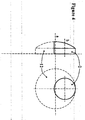
- Figures 1 and 2 show schematically a lens 2 and its optical axis a .
- a first bundle of rays 1, parallel to the optical axis a is focused into the focal spot 3 on the optical axis.
- a second bundle of rays 4 also parallel to the optical axis a , enters the lens at a location different then bundle 1 but is focused into the same focal spot 3 . Additional parallel bundles of rays would all be focused into the same focal spot. If lens 2 is rotated around a mechanical axis b parallel to but not collinear with the optical axis a as shown in Figure 2 all bundles of rays are still focused in one common focal spot 3 .
- the location of the focal spot 3 will change.
- the focal spot will follow a circular path c in a scanning plane perpendicular to the axis of rotation b .
- 2 is a bundle of illuminating rays
- an object located at the focal spot will scatter light into all directions; a portion of the scattered light is collected by lens 2 and collimated into the receiving bundle of rays 4 .
- the focal spot 3 will scan over objects located on the circular scan path c. Whenever the focal spot hits one of the objects, light will be backscattered into the receiving bundle 4 .
- this concept can be expanded to having several illuminating and receiving ray bundles or beams, all being focused into the same scanning spot, depending upon the nature of lens 2 .
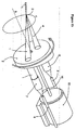
- Figure 3 shows a preferred embodiment of the present invention.
- Light from an optical source 5 preferably a laser diode, is launched into an optical fiber 6 .
- the light is guided to an optics 7 that forms the collimated illuminating beam 1 .
- This beam of light is focused by the scanning lens 2 into the focal spot on the optical axis a of lens 2 .
- the second collimating optics 8 defines a beam 4 , also focused by lens 2 into a focal spot on the optical axis a .
- the beams 1 and 4 intersect and form the measurement volume 3 shown in the enlargement in Fig. 3a .
- a particle that enters the measurement volume 3 will scatter light in all directions.
- Fiber 9 guides the received scattered light to a detector 10 that converts the optical signal into electrical signals. The electrical signal is then processes by a detector electronics 11 .
- Figure 3 also shows gradient index lenses as collimating optics 7 and 8 .
- Other collimating lens arrangements are also possible.
- the scanning lens 2 is shown as a simple plano-convex lens for ease of drawing. To achieve small focal spot sizes and therefore a small measurement volume it is necessary to use a better spherically corrected lens design. Possibilities include best form lenses, achromats, aspheres, or optics with multiple elements.
- FIG. 3 shows a possible location of the mechanical axis b and the optical axis a .
- the scanning lens 2 is cut from a larger lens 12 to reduce the weight of the rotating lens and to balance the rotating parts more easily.
- Figure 5 shows the optics of Fig. 3 mounted inside a probe housing 13 .
- the beams 1 and 4 fall through a probe window 14 into the fluid medium outside the probe.
- a motor 15 drives the shaft 16 to rotate the scanning lens 2 .
- Figure 5 therefore shows the optics arranged on a sliding base 17 that allows the optics to be moved inside the enclosure with respect to the fixed window.
- Figures 6a and 6b show a three dimensional view of the optics presented in Figure 3 .
- the circle c indicates the scanning path.
- Figure 6a one possible rotational position of the scanning lens 2 is shown. After rotating the scanning lens around axis b for about 270° the lens 2 assumes the position shown in Figure 6b .
- the illuminating beam 1 now focuses on another section of the scanning path c .
- the receiving optics 8 now also observes this spot.
- the lens 2 is continuously rotated around axis b the intersection of beams 1 and 4 will scan across all points on the scanning path 17 .
- each collimated beam parallel to the optical axis a falling through the scanning lens will be focused on the optical axis a and a section of the focused beam waist will coincide with the beam waists defined by other beams.
- Each combination of two of those beams defines a specific measurement volume.
- a possible application for this arrangement using several different illuminating wavelengths is to analyze not only the number and size of particles suspended in a fluid medium but also obtain spectroscopic information and thus draw conclusions about the chemical composition of different types of particles in the medium.
- the receiving detector is a spectrometer
- spectral information from individual scanned particles can be obtained through one receiving optics, otherwise several receiving optics can be used, each guiding light through a wavelength filter to a separate detector.
- Other possibilities include simultaneous single particle Raman spectroscopy or single particle fluorescence analysis.
- FIG. 7 shows an example of an interferometer setup. Collimated light 18 from a sufficiently coherent light source 19 is guided through a beamsplitter 20 and coupled into the optical fiber 6 . The arrangement of the scanning optics remains as shown in Figure 3 .
- Light backscattered from a rough object located in the scanning plane is collected and coupled into the receiving fiber 9 .
- the received light is emitted from fiber 9 and collimated by lens 21 into beam 22 .
- Beam 22 passes through the beamsplitter 19 and interferes with the reflected portion of illuminating beam 18 .
- the detector 23 will receive light of varying intensity as the scanner rotates and the measurement volumes scans across the rough surface.
- the intensity variations include information about the surface roughness of the scanned object.
- the present invention will find utility in the fields of analysis of particles suspended in stationary or moving fluid mediums where such analysis includes the number of particles in a sample, the size of the particles, and chemical composition of the particles.
- the present invention relates to a backscattering apparatus and method for optical scanning along a circular path using one or more optical illuminators and receivers. More particularly, it relates to an apparatus and method of focusing one or more beams of light into one or more beam spots, scanning the common beam spot(s) across a circular path and receiving light backscattered from the beam spot(s) with one or more detectors.
- a rotationally mounted scanning optics having an optical axis parallel to but not coaxial with the axis of rotation is used to accomplish these functions.
- a motor may be operatively linked to the scanning optics to cause the same to rotate at a constant angular velocity whereby, with appropriate signal generating detector and signal processing electronics, the number and size of particles suspended in a fluid medium exposed to the beam spot(s) can be determined.
Landscapes
- Chemical & Material Sciences (AREA)
- General Health & Medical Sciences (AREA)
- Life Sciences & Earth Sciences (AREA)
- Health & Medical Sciences (AREA)
- Analytical Chemistry (AREA)
- Biochemistry (AREA)
- Physics & Mathematics (AREA)
- General Physics & Mathematics (AREA)
- Immunology (AREA)
- Pathology (AREA)
- Dispersion Chemistry (AREA)
- Investigating Or Analysing Materials By Optical Means (AREA)
- Investigating, Analyzing Materials By Fluorescence Or Luminescence (AREA)
- Mechanical Optical Scanning Systems (AREA)
Applications Claiming Priority (2)
| Application Number | Priority Date | Filing Date | Title |
|---|---|---|---|
| US13248099P | 1999-05-04 | 1999-05-04 | |
| US132480P | 1999-05-04 |
Publications (3)
| Publication Number | Publication Date |
|---|---|
| EP1063512A2 true EP1063512A2 (fr) | 2000-12-27 |
| EP1063512A3 EP1063512A3 (fr) | 2003-08-13 |
| EP1063512B1 EP1063512B1 (fr) | 2006-08-09 |
Family
ID=22454252
Family Applications (1)
| Application Number | Title | Priority Date | Filing Date |
|---|---|---|---|
| EP00109519A Expired - Lifetime EP1063512B1 (fr) | 1999-05-04 | 2000-05-04 | Procédé et dispositif de charactérisation de particules en utilisant la réflection d'un faisceau à balayage multiple |
Country Status (7)
| Country | Link |
|---|---|
| US (1) | US6449042B1 (fr) |
| EP (1) | EP1063512B1 (fr) |
| JP (1) | JP4455730B2 (fr) |
| AT (1) | ATE335998T1 (fr) |
| AU (1) | AU780158B2 (fr) |
| CA (1) | CA2307509A1 (fr) |
| DE (1) | DE60029878T2 (fr) |
Cited By (13)
| Publication number | Priority date | Publication date | Assignee | Title |
|---|---|---|---|---|
| WO2003073077A1 (fr) * | 2002-02-22 | 2003-09-04 | Laser Sensor Technology, Inc. | Procédé et appareil de validation des résultats d'un système de balayage optique |
| GB2398382A (en) * | 2003-01-10 | 2004-08-18 | Horiba Ltd | Oil mist sensing device |
| US6787633B2 (en) | 2002-09-13 | 2004-09-07 | General Electric Company | Method and apparatus for preparing a poly(arylene ether) |
| WO2006021261A1 (fr) * | 2004-08-23 | 2006-03-02 | Hauni Maschinenbau Ag | Controle optique de produits de l'industrie du tabac |
| GB2429058B (en) * | 2004-03-06 | 2008-12-03 | Michael Trainer | Method and apparatus for determining the size and shape of particles |
| WO2009095679A2 (fr) * | 2008-02-01 | 2009-08-06 | Cambridge Consultants Limited | Dispositif photométrique |
| EP2191897A1 (fr) * | 2007-06-21 | 2010-06-02 | Gen-Probe Incorporated | Instrument et réceptacles pour effectuer les procédés |
| US8634072B2 (en) | 2004-03-06 | 2014-01-21 | Michael Trainer | Methods and apparatus for determining characteristics of particles |
| US8663922B2 (en) | 2005-03-10 | 2014-03-04 | Gen-Probe Incorporated | Systems and methods for detecting multiple optical signals |
| US8718948B2 (en) | 2011-02-24 | 2014-05-06 | Gen-Probe Incorporated | Systems and methods for distinguishing optical signals of different modulation frequencies in an optical signal detector |
| WO2016074832A1 (fr) * | 2014-11-13 | 2016-05-19 | Robert Bosch Gmbh | Compteur de particules |
| EP3252446A1 (fr) * | 2016-05-30 | 2017-12-06 | Hitachi High-Tech Analytical Science Limited | Ensemble détecteur pour l'analyse de composition élémentaire d'un échantillon par spectroscopie d'émission optique |
| CN109765159A (zh) * | 2019-03-13 | 2019-05-17 | 陈美香 | 一种粉尘浓度检测仪 |
Families Citing this family (21)
| Publication number | Priority date | Publication date | Assignee | Title |
|---|---|---|---|---|
| US7496540B2 (en) | 2002-03-27 | 2009-02-24 | Convergys Cmg Utah | System and method for securing digital content |
| JP2004109010A (ja) * | 2002-09-19 | 2004-04-08 | Otsuka Denshi Co Ltd | 散乱光測定装置 |
| US7030383B2 (en) * | 2003-08-04 | 2006-04-18 | Cadent Ltd. | Speckle reduction method and apparatus |
| US7596545B1 (en) | 2004-08-27 | 2009-09-29 | University Of Kansas | Automated data entry system |
| DE102006043013A1 (de) * | 2006-09-13 | 2008-03-27 | Robert Bosch Gmbh | Vorrichtung und Verfahren zur Messung wenigstens eines Parameters von Partikeln in einem Fluid |
| JP4389991B2 (ja) * | 2007-10-26 | 2009-12-24 | ソニー株式会社 | 微小粒子の光学的測定方法及び光学的測定装置 |
| US9007580B2 (en) | 2011-04-11 | 2015-04-14 | Schlumberger Norge As | Method and apparatus for measuring particle size distribution in drilling fluid |
| US8427640B2 (en) | 2008-10-23 | 2013-04-23 | M-I L.L.C. | Method and apparatus for measuring particle size distribution in drilling fluid |
| US8541355B2 (en) | 2009-11-04 | 2013-09-24 | Colgate-Palmolive Company | Process to produce stable suspending system |
| UY33005A (es) | 2009-11-04 | 2010-12-31 | Colgate Palmolive Co | Celulosa microfibrosa con una distribucion del tamaño de las particulas que le permite ser utilizada en composiciones surfactantes estructuradas |
| CN103328955B (zh) | 2011-01-20 | 2017-10-20 | 奥林巴斯株式会社 | 利用来自单个发光粒子的光的检测的光分析方法和光分析装置 |
| CN103733049B (zh) | 2011-08-15 | 2016-01-20 | 奥林巴斯株式会社 | 利用单个发光粒子检测的光分析装置、光分析方法以及光分析用计算机程序 |
| EP2749867B1 (fr) | 2011-08-26 | 2017-05-10 | Olympus Corporation | Analyseur optique utilisant la détection de particules à émission de lumière |
| DE102013111256B4 (de) * | 2013-10-11 | 2021-06-10 | Sick Engineering Gmbh | Vorrichtung zur Messung der Lichtstreuung und Verfahren zum Prüfen einer Empfangsoptik |
| DE102014109166A1 (de) | 2014-07-01 | 2016-01-21 | Parsum-Gesellschaft für Partikel-, Strömungs- und Umweltmeßtechnik mbH | Verfahren zur Partikelformbestimmung |
| DE102015116474A1 (de) | 2015-09-29 | 2017-03-30 | Hochschule Reutlingen | Verfahren zum Ermitteln von Deskriptoren, welche mit Eigenschaften eines Partikelkollektivs korrelieren |
| JPWO2017098597A1 (ja) | 2015-12-09 | 2018-10-11 | オリンパス株式会社 | 単一発光粒子検出を用いた光分析方法及び光分析装置 |
| US9816859B1 (en) * | 2016-05-13 | 2017-11-14 | The United States Of America As Represented By The Secretary Of The Navy | Imaging optical beam attenuation coefficient meter |
| JP6972165B2 (ja) * | 2017-03-31 | 2021-11-24 | プレシテック ゲーエムベーハー ウント ツェーオー カーゲー | 付加製造用の装置及び方法 |
| DE102018212685B4 (de) * | 2018-07-30 | 2023-06-22 | Robert Bosch Gmbh | Optische Partikelsensorvorrichtung und entsprechendes Partikelmessverfahren |
| CN112119343B (zh) * | 2019-02-02 | 2023-04-21 | 深圳市大疆创新科技有限公司 | 扫描模组及测距装置 |
Citations (5)
| Publication number | Priority date | Publication date | Assignee | Title |
|---|---|---|---|---|
| GB2044445A (en) * | 1979-01-02 | 1980-10-15 | Coulter Electronics | Measuring scatter distribution |
| US4938555A (en) * | 1988-08-16 | 1990-07-03 | Sc Technology, Int. | Optical switch |
| US5109459A (en) * | 1989-12-23 | 1992-04-28 | Dornier Luftfahrt Gmbh | Fiber optic scanner |
| EP0566873A2 (fr) * | 1992-03-25 | 1993-10-27 | The Spectranetics Corporation | Embout en deux pièces pour cathéter à fibres optiques |
| EP0790517A2 (fr) * | 1996-02-16 | 1997-08-20 | Presstek, Inc. | Appareil de reproduction d'image par décharger à laser et élément de focalisation pour celui-ci |
Family Cites Families (12)
| Publication number | Priority date | Publication date | Assignee | Title |
|---|---|---|---|---|
| US4387993A (en) | 1981-06-25 | 1983-06-14 | Tsi Incorporated | Particle size measuring method and apparatus |
| US4506979A (en) * | 1981-12-08 | 1985-03-26 | Lockheed Corporation | Compact radiation fringe velocimeter for measuring in three dimensions |
| US4906094A (en) | 1987-04-23 | 1990-03-06 | Sumitomo Chemical Co. Ltd. | Fine particle measuring method and system and a flow cell for use in the system |
| US4854705A (en) | 1988-04-05 | 1989-08-08 | Aerometrics, Inc. | Method and apparatus to determine the size and velocity of particles using light scatter detection from confocal beams |
| FR2649207B1 (fr) * | 1989-06-30 | 1992-10-09 | Thomson Csf | Dispositif embarque dans un engin mobile, pour l'obtention de signaux representatifs de la vitesse relative de l'engin par rapport a un fluide ambiant et appareil de mesure comportant un tel dispositif |
| US5012118A (en) | 1989-12-13 | 1991-04-30 | Preikschat F K | Apparatus and method for particle analysis |
| US5168401A (en) | 1991-05-07 | 1992-12-01 | Spectra Diode Laboratories, Inc. | Brightness conserving optical system for modifying beam symmetry |
| JPH07286953A (ja) | 1994-04-19 | 1995-10-31 | Toa Medical Electronics Co Ltd | イメージングフローサイトメータ |
| US5815264A (en) * | 1994-09-21 | 1998-09-29 | Laser Sensor Technology, Inc | System for acquiring an image of a multi-phase fluid by measuring backscattered light |
| JP3140664B2 (ja) | 1995-06-30 | 2001-03-05 | 松下電器産業株式会社 | 異物検査方法及び装置 |
| US5790246A (en) | 1996-04-18 | 1998-08-04 | Montores Pty. Ltd. | Apparatus and network for determining a parameter of a particle in a fluid employing detector and processor |
| US5751423A (en) * | 1996-12-06 | 1998-05-12 | United Sciences, Inc. | Opacity and forward scattering monitor using beam-steered solid-state light source |
-
2000
- 2000-05-04 AU AU32526/00A patent/AU780158B2/en not_active Ceased
- 2000-05-04 AT AT00109519T patent/ATE335998T1/de not_active IP Right Cessation
- 2000-05-04 DE DE60029878T patent/DE60029878T2/de not_active Expired - Lifetime
- 2000-05-04 CA CA002307509A patent/CA2307509A1/fr not_active Abandoned
- 2000-05-04 EP EP00109519A patent/EP1063512B1/fr not_active Expired - Lifetime
- 2000-05-04 US US09/565,626 patent/US6449042B1/en not_active Expired - Lifetime
- 2000-05-08 JP JP2000134898A patent/JP4455730B2/ja not_active Expired - Fee Related
Patent Citations (5)
| Publication number | Priority date | Publication date | Assignee | Title |
|---|---|---|---|---|
| GB2044445A (en) * | 1979-01-02 | 1980-10-15 | Coulter Electronics | Measuring scatter distribution |
| US4938555A (en) * | 1988-08-16 | 1990-07-03 | Sc Technology, Int. | Optical switch |
| US5109459A (en) * | 1989-12-23 | 1992-04-28 | Dornier Luftfahrt Gmbh | Fiber optic scanner |
| EP0566873A2 (fr) * | 1992-03-25 | 1993-10-27 | The Spectranetics Corporation | Embout en deux pièces pour cathéter à fibres optiques |
| EP0790517A2 (fr) * | 1996-02-16 | 1997-08-20 | Presstek, Inc. | Appareil de reproduction d'image par décharger à laser et élément de focalisation pour celui-ci |
Cited By (24)
| Publication number | Priority date | Publication date | Assignee | Title |
|---|---|---|---|---|
| US6940064B2 (en) | 2002-02-22 | 2005-09-06 | Laser Sensor Technology, Inc. | Method and apparatus for validating the operation of an optical scanning device |
| WO2003073077A1 (fr) * | 2002-02-22 | 2003-09-04 | Laser Sensor Technology, Inc. | Procédé et appareil de validation des résultats d'un système de balayage optique |
| US6787633B2 (en) | 2002-09-13 | 2004-09-07 | General Electric Company | Method and apparatus for preparing a poly(arylene ether) |
| GB2398382B (en) * | 2003-01-10 | 2006-02-01 | Horiba Ltd | Oil mist sensing device |
| GB2398382A (en) * | 2003-01-10 | 2004-08-18 | Horiba Ltd | Oil mist sensing device |
| GB2429058B (en) * | 2004-03-06 | 2008-12-03 | Michael Trainer | Method and apparatus for determining the size and shape of particles |
| US8634072B2 (en) | 2004-03-06 | 2014-01-21 | Michael Trainer | Methods and apparatus for determining characteristics of particles |
| WO2006021261A1 (fr) * | 2004-08-23 | 2006-03-02 | Hauni Maschinenbau Ag | Controle optique de produits de l'industrie du tabac |
| US9726607B2 (en) | 2005-03-10 | 2017-08-08 | Gen-Probe Incorporated | Systems and methods for detecting multiple optical signals |
| US8663922B2 (en) | 2005-03-10 | 2014-03-04 | Gen-Probe Incorporated | Systems and methods for detecting multiple optical signals |
| EP2191897A1 (fr) * | 2007-06-21 | 2010-06-02 | Gen-Probe Incorporated | Instrument et réceptacles pour effectuer les procédés |
| US10086342B2 (en) | 2007-06-21 | 2018-10-02 | Gen-Probe Incorporated | Multi-channel optical measurement instrument |
| US9458451B2 (en) | 2007-06-21 | 2016-10-04 | Gen-Probe Incorporated | Multi-channel optical measurement instrument |
| WO2009095679A2 (fr) * | 2008-02-01 | 2009-08-06 | Cambridge Consultants Limited | Dispositif photométrique |
| WO2009095679A3 (fr) * | 2008-02-01 | 2009-12-10 | Cambridge Consultants Limited | Dispositif photométrique |
| US8742368B2 (en) | 2008-02-01 | 2014-06-03 | Cambridge Consultants Limited | Device and method for measuring scattering of radiation |
| US8718948B2 (en) | 2011-02-24 | 2014-05-06 | Gen-Probe Incorporated | Systems and methods for distinguishing optical signals of different modulation frequencies in an optical signal detector |
| US9915613B2 (en) | 2011-02-24 | 2018-03-13 | Gen-Probe Incorporated | Systems and methods for distinguishing optical signals of different modulation frequencies in an optical signal detector |
| US10641707B2 (en) | 2011-02-24 | 2020-05-05 | Gen-Probe Incorporated | Systems and methods for distinguishing optical signals of different modulation frequencies in an optical signal detector |
| WO2016074832A1 (fr) * | 2014-11-13 | 2016-05-19 | Robert Bosch Gmbh | Compteur de particules |
| EP3252446A1 (fr) * | 2016-05-30 | 2017-12-06 | Hitachi High-Tech Analytical Science Limited | Ensemble détecteur pour l'analyse de composition élémentaire d'un échantillon par spectroscopie d'émission optique |
| US10197445B2 (en) | 2016-05-30 | 2019-02-05 | Hitachi High-Tech Analytical Science Limited | Detector assembly for analysis of elemental composition of a sample using optical emission spectroscopy |
| US10527496B2 (en) | 2016-05-30 | 2020-01-07 | Hitachi High-Tech Analytical Science Limited | Detector assembly for analysis of elemental composition of a sample using optical emission spectroscopy |
| CN109765159A (zh) * | 2019-03-13 | 2019-05-17 | 陈美香 | 一种粉尘浓度检测仪 |
Also Published As
| Publication number | Publication date |
|---|---|
| JP2001033384A (ja) | 2001-02-09 |
| AU3252600A (en) | 2000-11-16 |
| EP1063512B1 (fr) | 2006-08-09 |
| CA2307509A1 (fr) | 2000-11-04 |
| AU780158B2 (en) | 2005-03-03 |
| EP1063512A3 (fr) | 2003-08-13 |
| DE60029878D1 (de) | 2006-09-21 |
| DE60029878T2 (de) | 2007-03-15 |
| US6449042B1 (en) | 2002-09-10 |
| ATE335998T1 (de) | 2006-09-15 |
| JP4455730B2 (ja) | 2010-04-21 |
Similar Documents
| Publication | Publication Date | Title |
|---|---|---|
| US6449042B1 (en) | Method and apparatus for particle assessment using multiple scanning beam reflectance | |
| US11313721B2 (en) | Compact spectrometer | |
| US4022529A (en) | Feature extraction system for extracting a predetermined feature from a signal | |
| US4645340A (en) | Optically reflective sphere for efficient collection of Raman scattered light | |
| US10295408B2 (en) | Raman spectroscopy system | |
| US11441950B2 (en) | Apparatus and method for reducing interference in an optical spectroscopy probe having a collimated sample beam | |
| EP3743699A1 (fr) | Appareil pour mise en oeuvre d'une spectroscopie raman | |
| EP3435072B1 (fr) | Appareil d'inspection de spectre raman | |
| CN105181656A (zh) | 激光差动共焦诱导击穿-拉曼光谱成像探测方法及装置 | |
| USRE32598E (en) | Feature extraction system for extracting a predetermined feature from a signal | |
| US6809812B2 (en) | Spectral analysis system with moving objective lens | |
| US20100014076A1 (en) | Spectrometric apparatus for measuring shifted spectral distributions | |
| CN104931481A (zh) | 激光双轴差动共焦诱导击穿-拉曼光谱成像探测方法与装置 | |
| JPH0224535A (ja) | 粒子解析装置 | |
| JP2022512143A (ja) | 光ビーム走査型顕微分光法のための装置と方法 | |
| CN104990908A (zh) | 激光双轴共焦诱导击穿-拉曼光谱成像探测方法与装置 | |
| CN212059104U (zh) | 一种宽光谱高灵敏度拉曼光谱仪 | |
| CN214011030U (zh) | 一种多模式显微高光谱成像仪 | |
| JP5363976B2 (ja) | 反射率測定による特性評価の測定装置と方法 | |
| CN115078283A (zh) | 一种一体式紫外分光光谱仪及系统 |
Legal Events
| Date | Code | Title | Description |
|---|---|---|---|
| PUAI | Public reference made under article 153(3) epc to a published international application that has entered the european phase |
Free format text: ORIGINAL CODE: 0009012 |
|
| AK | Designated contracting states |
Kind code of ref document: A2 Designated state(s): AT BE CH CY DE DK ES FI FR GB GR IE IT LI LU MC NL PT SE |
|
| AX | Request for extension of the european patent |
Free format text: AL;LT;LV;MK;RO;SI |
|
| PUAL | Search report despatched |
Free format text: ORIGINAL CODE: 0009013 |
|
| AK | Designated contracting states |
Designated state(s): AT BE CH CY DE DK ES FI FR GB GR IE IT LI LU MC NL PT SE |
|
| AX | Request for extension of the european patent |
Extension state: AL LT LV MK RO SI |
|
| 17P | Request for examination filed |
Effective date: 20040204 |
|
| AKX | Designation fees paid |
Designated state(s): AT BE CH CY DE DK ES FI FR GB GR IE IT LI LU MC NL PT SE |
|
| 17Q | First examination report despatched |
Effective date: 20040413 |
|
| RAP1 | Party data changed (applicant data changed or rights of an application transferred) |
Owner name: METTLER-TOLEDO AUTOCHEM, INC. |
|
| GRAP | Despatch of communication of intention to grant a patent |
Free format text: ORIGINAL CODE: EPIDOSNIGR1 |
|
| GRAS | Grant fee paid |
Free format text: ORIGINAL CODE: EPIDOSNIGR3 |
|
| GRAA | (expected) grant |
Free format text: ORIGINAL CODE: 0009210 |
|
| RAP1 | Party data changed (applicant data changed or rights of an application transferred) |
Owner name: METTLER-TOLEDO AUTOCHEM, INC. |
|
| RIN1 | Information on inventor provided before grant (corrected) |
Inventor name: HAMANN, OLIVER |
|
| AK | Designated contracting states |
Kind code of ref document: B1 Designated state(s): AT BE CH CY DE DK ES FI FR GB GR IE IT LI LU MC NL PT SE |
|
| PG25 | Lapsed in a contracting state [announced via postgrant information from national office to epo] |
Ref country code: IT Free format text: LAPSE BECAUSE OF FAILURE TO SUBMIT A TRANSLATION OF THE DESCRIPTION OR TO PAY THE FEE WITHIN THE PRESCRIBED TIME-LIMIT;WARNING: LAPSES OF ITALIAN PATENTS WITH EFFECTIVE DATE BEFORE 2007 MAY HAVE OCCURRED AT ANY TIME BEFORE 2007. THE CORRECT EFFECTIVE DATE MAY BE DIFFERENT FROM THE ONE RECORDED. Effective date: 20060809 Ref country code: FI Free format text: LAPSE BECAUSE OF FAILURE TO SUBMIT A TRANSLATION OF THE DESCRIPTION OR TO PAY THE FEE WITHIN THE PRESCRIBED TIME-LIMIT Effective date: 20060809 Ref country code: AT Free format text: LAPSE BECAUSE OF FAILURE TO SUBMIT A TRANSLATION OF THE DESCRIPTION OR TO PAY THE FEE WITHIN THE PRESCRIBED TIME-LIMIT Effective date: 20060809 Ref country code: BE Free format text: LAPSE BECAUSE OF FAILURE TO SUBMIT A TRANSLATION OF THE DESCRIPTION OR TO PAY THE FEE WITHIN THE PRESCRIBED TIME-LIMIT Effective date: 20060809 |
|
| REG | Reference to a national code |
Ref country code: GB Ref legal event code: FG4D |
|
| REG | Reference to a national code |
Ref country code: CH Ref legal event code: EP |
|
| REG | Reference to a national code |
Ref country code: IE Ref legal event code: FG4D |
|
| REF | Corresponds to: |
Ref document number: 60029878 Country of ref document: DE Date of ref document: 20060921 Kind code of ref document: P |
|
| PG25 | Lapsed in a contracting state [announced via postgrant information from national office to epo] |
Ref country code: DK Free format text: LAPSE BECAUSE OF FAILURE TO SUBMIT A TRANSLATION OF THE DESCRIPTION OR TO PAY THE FEE WITHIN THE PRESCRIBED TIME-LIMIT Effective date: 20061109 Ref country code: SE Free format text: LAPSE BECAUSE OF FAILURE TO SUBMIT A TRANSLATION OF THE DESCRIPTION OR TO PAY THE FEE WITHIN THE PRESCRIBED TIME-LIMIT Effective date: 20061109 |
|
| PG25 | Lapsed in a contracting state [announced via postgrant information from national office to epo] |
Ref country code: ES Free format text: LAPSE BECAUSE OF FAILURE TO SUBMIT A TRANSLATION OF THE DESCRIPTION OR TO PAY THE FEE WITHIN THE PRESCRIBED TIME-LIMIT Effective date: 20061120 |
|
| PG25 | Lapsed in a contracting state [announced via postgrant information from national office to epo] |
Ref country code: PT Free format text: LAPSE BECAUSE OF FAILURE TO SUBMIT A TRANSLATION OF THE DESCRIPTION OR TO PAY THE FEE WITHIN THE PRESCRIBED TIME-LIMIT Effective date: 20070109 |
|
| ET | Fr: translation filed | ||
| PLBE | No opposition filed within time limit |
Free format text: ORIGINAL CODE: 0009261 |
|
| STAA | Information on the status of an ep patent application or granted ep patent |
Free format text: STATUS: NO OPPOSITION FILED WITHIN TIME LIMIT |
|
| 26N | No opposition filed |
Effective date: 20070510 |
|
| REG | Reference to a national code |
Ref country code: CH Ref legal event code: NV Representative=s name: E. BLUM & CO. AG PATENT- UND MARKENANWAELTE VSP |
|
| PG25 | Lapsed in a contracting state [announced via postgrant information from national office to epo] |
Ref country code: MC Free format text: LAPSE BECAUSE OF NON-PAYMENT OF DUE FEES Effective date: 20070531 |
|
| PG25 | Lapsed in a contracting state [announced via postgrant information from national office to epo] |
Ref country code: GR Free format text: LAPSE BECAUSE OF FAILURE TO SUBMIT A TRANSLATION OF THE DESCRIPTION OR TO PAY THE FEE WITHIN THE PRESCRIBED TIME-LIMIT Effective date: 20061110 |
|
| PG25 | Lapsed in a contracting state [announced via postgrant information from national office to epo] |
Ref country code: CY Free format text: LAPSE BECAUSE OF FAILURE TO SUBMIT A TRANSLATION OF THE DESCRIPTION OR TO PAY THE FEE WITHIN THE PRESCRIBED TIME-LIMIT Effective date: 20060809 Ref country code: LU Free format text: LAPSE BECAUSE OF NON-PAYMENT OF DUE FEES Effective date: 20070504 |
|
| REG | Reference to a national code |
Ref country code: FR Ref legal event code: PLFP Year of fee payment: 17 |
|
| PGFP | Annual fee paid to national office [announced via postgrant information from national office to epo] |
Ref country code: NL Payment date: 20160506 Year of fee payment: 17 |
|
| PGFP | Annual fee paid to national office [announced via postgrant information from national office to epo] |
Ref country code: DE Payment date: 20160524 Year of fee payment: 17 Ref country code: CH Payment date: 20160425 Year of fee payment: 17 Ref country code: GB Payment date: 20160426 Year of fee payment: 17 Ref country code: IE Payment date: 20160426 Year of fee payment: 17 |
|
| PGFP | Annual fee paid to national office [announced via postgrant information from national office to epo] |
Ref country code: FR Payment date: 20160428 Year of fee payment: 17 |
|
| REG | Reference to a national code |
Ref country code: DE Ref legal event code: R119 Ref document number: 60029878 Country of ref document: DE |
|
| REG | Reference to a national code |
Ref country code: CH Ref legal event code: PL |
|
| REG | Reference to a national code |
Ref country code: NL Ref legal event code: MM Effective date: 20170601 |
|
| GBPC | Gb: european patent ceased through non-payment of renewal fee |
Effective date: 20170504 |
|
| REG | Reference to a national code |
Ref country code: IE Ref legal event code: MM4A |
|
| PG25 | Lapsed in a contracting state [announced via postgrant information from national office to epo] |
Ref country code: LI Free format text: LAPSE BECAUSE OF NON-PAYMENT OF DUE FEES Effective date: 20170531 Ref country code: CH Free format text: LAPSE BECAUSE OF NON-PAYMENT OF DUE FEES Effective date: 20170531 |
|
| REG | Reference to a national code |
Ref country code: FR Ref legal event code: ST Effective date: 20180131 |
|
| PG25 | Lapsed in a contracting state [announced via postgrant information from national office to epo] |
Ref country code: NL Free format text: LAPSE BECAUSE OF NON-PAYMENT OF DUE FEES Effective date: 20170601 |
|
| PG25 | Lapsed in a contracting state [announced via postgrant information from national office to epo] |
Ref country code: GB Free format text: LAPSE BECAUSE OF NON-PAYMENT OF DUE FEES Effective date: 20170504 Ref country code: DE Free format text: LAPSE BECAUSE OF NON-PAYMENT OF DUE FEES Effective date: 20171201 Ref country code: IE Free format text: LAPSE BECAUSE OF NON-PAYMENT OF DUE FEES Effective date: 20170504 |
|
| PG25 | Lapsed in a contracting state [announced via postgrant information from national office to epo] |
Ref country code: FR Free format text: LAPSE BECAUSE OF NON-PAYMENT OF DUE FEES Effective date: 20170531 |