EP1063485B1 - Device and process for air separation by cryogenic distillation - Google Patents
Device and process for air separation by cryogenic distillation Download PDFInfo
- Publication number
- EP1063485B1 EP1063485B1 EP00401768A EP00401768A EP1063485B1 EP 1063485 B1 EP1063485 B1 EP 1063485B1 EP 00401768 A EP00401768 A EP 00401768A EP 00401768 A EP00401768 A EP 00401768A EP 1063485 B1 EP1063485 B1 EP 1063485B1
- Authority
- EP
- European Patent Office
- Prior art keywords
- pressure column
- low
- sent
- column
- condenser
- Prior art date
- Legal status (The legal status is an assumption and is not a legal conclusion. Google has not performed a legal analysis and makes no representation as to the accuracy of the status listed.)
- Expired - Lifetime
Links
Images

Classifications
-
- F—MECHANICAL ENGINEERING; LIGHTING; HEATING; WEAPONS; BLASTING
- F25—REFRIGERATION OR COOLING; COMBINED HEATING AND REFRIGERATION SYSTEMS; HEAT PUMP SYSTEMS; MANUFACTURE OR STORAGE OF ICE; LIQUEFACTION SOLIDIFICATION OF GASES
- F25J—LIQUEFACTION, SOLIDIFICATION OR SEPARATION OF GASES OR GASEOUS OR LIQUEFIED GASEOUS MIXTURES BY PRESSURE AND COLD TREATMENT OR BY BRINGING THEM INTO THE SUPERCRITICAL STATE
- F25J3/00—Processes or apparatus for separating the constituents of gaseous or liquefied gaseous mixtures involving the use of liquefaction or solidification
- F25J3/02—Processes or apparatus for separating the constituents of gaseous or liquefied gaseous mixtures involving the use of liquefaction or solidification by rectification, i.e. by continuous interchange of heat and material between a vapour stream and a liquid stream
- F25J3/04—Processes or apparatus for separating the constituents of gaseous or liquefied gaseous mixtures involving the use of liquefaction or solidification by rectification, i.e. by continuous interchange of heat and material between a vapour stream and a liquid stream for air
- F25J3/04763—Start-up or control of the process; Details of the apparatus used
- F25J3/04866—Construction and layout of air fractionation equipments, e.g. valves, machines
- F25J3/04872—Vertical layout of cold equipments within in the cold box, e.g. columns, heat exchangers etc.
- F25J3/04878—Side by side arrangement of multiple vessels in a main column system, wherein the vessels are normally mounted one upon the other or forming different sections of the same column
-
- F—MECHANICAL ENGINEERING; LIGHTING; HEATING; WEAPONS; BLASTING
- F25—REFRIGERATION OR COOLING; COMBINED HEATING AND REFRIGERATION SYSTEMS; HEAT PUMP SYSTEMS; MANUFACTURE OR STORAGE OF ICE; LIQUEFACTION SOLIDIFICATION OF GASES
- F25J—LIQUEFACTION, SOLIDIFICATION OR SEPARATION OF GASES OR GASEOUS OR LIQUEFIED GASEOUS MIXTURES BY PRESSURE AND COLD TREATMENT OR BY BRINGING THEM INTO THE SUPERCRITICAL STATE
- F25J3/00—Processes or apparatus for separating the constituents of gaseous or liquefied gaseous mixtures involving the use of liquefaction or solidification
- F25J3/02—Processes or apparatus for separating the constituents of gaseous or liquefied gaseous mixtures involving the use of liquefaction or solidification by rectification, i.e. by continuous interchange of heat and material between a vapour stream and a liquid stream
- F25J3/04—Processes or apparatus for separating the constituents of gaseous or liquefied gaseous mixtures involving the use of liquefaction or solidification by rectification, i.e. by continuous interchange of heat and material between a vapour stream and a liquid stream for air
- F25J3/04248—Generation of cold for compensating heat leaks or liquid production, e.g. by Joule-Thompson expansion
- F25J3/04284—Generation of cold for compensating heat leaks or liquid production, e.g. by Joule-Thompson expansion using internal refrigeration by open-loop gas work expansion, e.g. of intermediate or oxygen enriched (waste-)streams
- F25J3/0429—Generation of cold for compensating heat leaks or liquid production, e.g. by Joule-Thompson expansion using internal refrigeration by open-loop gas work expansion, e.g. of intermediate or oxygen enriched (waste-)streams of feed air, e.g. used as waste or product air or expanded into an auxiliary column
- F25J3/04303—Lachmann expansion, i.e. expanded into oxygen producing or low pressure column
-
- F—MECHANICAL ENGINEERING; LIGHTING; HEATING; WEAPONS; BLASTING
- F25—REFRIGERATION OR COOLING; COMBINED HEATING AND REFRIGERATION SYSTEMS; HEAT PUMP SYSTEMS; MANUFACTURE OR STORAGE OF ICE; LIQUEFACTION SOLIDIFICATION OF GASES
- F25J—LIQUEFACTION, SOLIDIFICATION OR SEPARATION OF GASES OR GASEOUS OR LIQUEFIED GASEOUS MIXTURES BY PRESSURE AND COLD TREATMENT OR BY BRINGING THEM INTO THE SUPERCRITICAL STATE
- F25J3/00—Processes or apparatus for separating the constituents of gaseous or liquefied gaseous mixtures involving the use of liquefaction or solidification
- F25J3/02—Processes or apparatus for separating the constituents of gaseous or liquefied gaseous mixtures involving the use of liquefaction or solidification by rectification, i.e. by continuous interchange of heat and material between a vapour stream and a liquid stream
- F25J3/04—Processes or apparatus for separating the constituents of gaseous or liquefied gaseous mixtures involving the use of liquefaction or solidification by rectification, i.e. by continuous interchange of heat and material between a vapour stream and a liquid stream for air
- F25J3/0446—Processes or apparatus for separating the constituents of gaseous or liquefied gaseous mixtures involving the use of liquefaction or solidification by rectification, i.e. by continuous interchange of heat and material between a vapour stream and a liquid stream for air using the heat generated by mixing two different phases
- F25J3/04466—Processes or apparatus for separating the constituents of gaseous or liquefied gaseous mixtures involving the use of liquefaction or solidification by rectification, i.e. by continuous interchange of heat and material between a vapour stream and a liquid stream for air using the heat generated by mixing two different phases for producing oxygen as a mixing column overhead gas by mixing gaseous air feed and liquid oxygen
-
- F—MECHANICAL ENGINEERING; LIGHTING; HEATING; WEAPONS; BLASTING
- F25—REFRIGERATION OR COOLING; COMBINED HEATING AND REFRIGERATION SYSTEMS; HEAT PUMP SYSTEMS; MANUFACTURE OR STORAGE OF ICE; LIQUEFACTION SOLIDIFICATION OF GASES
- F25J—LIQUEFACTION, SOLIDIFICATION OR SEPARATION OF GASES OR GASEOUS OR LIQUEFIED GASEOUS MIXTURES BY PRESSURE AND COLD TREATMENT OR BY BRINGING THEM INTO THE SUPERCRITICAL STATE
- F25J2200/00—Processes or apparatus using separation by rectification
- F25J2200/04—Processes or apparatus using separation by rectification in a dual pressure main column system
- F25J2200/06—Processes or apparatus using separation by rectification in a dual pressure main column system in a classical double column flow-sheet, i.e. with thermal coupling by a main reboiler-condenser in the bottom of low pressure respectively top of high pressure column
-
- F—MECHANICAL ENGINEERING; LIGHTING; HEATING; WEAPONS; BLASTING
- F25—REFRIGERATION OR COOLING; COMBINED HEATING AND REFRIGERATION SYSTEMS; HEAT PUMP SYSTEMS; MANUFACTURE OR STORAGE OF ICE; LIQUEFACTION SOLIDIFICATION OF GASES
- F25J—LIQUEFACTION, SOLIDIFICATION OR SEPARATION OF GASES OR GASEOUS OR LIQUEFIED GASEOUS MIXTURES BY PRESSURE AND COLD TREATMENT OR BY BRINGING THEM INTO THE SUPERCRITICAL STATE
- F25J2235/00—Processes or apparatus involving steps for increasing the pressure or for conveying of liquid process streams
- F25J2235/50—Processes or apparatus involving steps for increasing the pressure or for conveying of liquid process streams the fluid being oxygen
-
- F—MECHANICAL ENGINEERING; LIGHTING; HEATING; WEAPONS; BLASTING
- F25—REFRIGERATION OR COOLING; COMBINED HEATING AND REFRIGERATION SYSTEMS; HEAT PUMP SYSTEMS; MANUFACTURE OR STORAGE OF ICE; LIQUEFACTION SOLIDIFICATION OF GASES
- F25J—LIQUEFACTION, SOLIDIFICATION OR SEPARATION OF GASES OR GASEOUS OR LIQUEFIED GASEOUS MIXTURES BY PRESSURE AND COLD TREATMENT OR BY BRINGING THEM INTO THE SUPERCRITICAL STATE
- F25J2250/00—Details related to the use of reboiler-condensers
- F25J2250/30—External or auxiliary boiler-condenser in general, e.g. without a specified fluid or one fluid is not a primary air component or an intermediate fluid
- F25J2250/40—One fluid being air
-
- F—MECHANICAL ENGINEERING; LIGHTING; HEATING; WEAPONS; BLASTING
- F25—REFRIGERATION OR COOLING; COMBINED HEATING AND REFRIGERATION SYSTEMS; HEAT PUMP SYSTEMS; MANUFACTURE OR STORAGE OF ICE; LIQUEFACTION SOLIDIFICATION OF GASES
- F25J—LIQUEFACTION, SOLIDIFICATION OR SEPARATION OF GASES OR GASEOUS OR LIQUEFIED GASEOUS MIXTURES BY PRESSURE AND COLD TREATMENT OR BY BRINGING THEM INTO THE SUPERCRITICAL STATE
- F25J2250/00—Details related to the use of reboiler-condensers
- F25J2250/30—External or auxiliary boiler-condenser in general, e.g. without a specified fluid or one fluid is not a primary air component or an intermediate fluid
- F25J2250/52—One fluid being oxygen enriched compared to air, e.g. "crude oxygen"
Definitions
- the invention proposed here relates to the field of gas distillation air and especially to a device and proceeds from air separation by cryogenic distillation. It improves the extraction efficiency of oxygen and so the energy performance on the patterns of distillation which does not ordinarily include a supply of liquefied air columns and whose cooling production is ensured by an air release (oil brake turbine, generator or auto-boosted).
- the gains of this invention when it is implanted on an air separation unit are of 3.5% (see case below) in oxygen separation energy.
- the basic distillation processes on which the invention can be used are processes that do not ordinarily involve feeding of liquid air in the distillation columns.
- These basic processes are processes for separating gases from the air with air compression, pre-cooling of compressed air, air cleaning, cooling of air in a main exchanger, separation of air in a distillation column comprising at least one medium pressure column and a column low pressure and subcooling liquids coming in reflux of the medium pressure column to the low pressure column.
- Double column (single cycle) producing low oxygen outlet pressure cold box.
- An application case production of impure oxygen with medium pressure MP column and low pressure BP under pressure (recovery of the waste).
- the loss of efficiency due to the reflux decline (more difficult distillation in the MP column) is sorely feel.
- This invention will improve the efficiency in this case.
- EP-A-0381319 discloses a column system in which an air flow rate vaporizes against a flow containing 95 vol.% oxygen.
- US-A-5765396 relates to a conventional pump process in which a air flow condenses against liquid containing between 98 and 100 mol%.
- US-A-5582035 and US-A-5291737 disclose separation methods of air with mixing column in which all the air enters the columns in gaseous form.
- US-A-3754406 proposes to vaporize rich liquid from the column medium pressure of a double column against medium nitrogen gas pressure. Air is liquefied by heat exchange with liquid oxygen pumped and sent to the low pressure column.
- an air separation apparatus according to claim 1.
- At least partially condensed air sent to the Low pressure column is the only flow of liquefied air to the system of columns.
- the apparatus comprises means for relaxing the air with production work before sending it to the second vaporizer-condenser and / or means to cool the air to its dew point before sending it to second vaporizer-condenser.
- At least partially condensed air can be sent to the column low pressure and / or medium pressure column and / or other column of the column system.
- the apparatus comprises a powered mixing column at the top by a rich oxygen liquid from the column tank-fed by a more volatile gas than the liquid rich in oxygen.
- the low pressure column has no overhead condenser.
- Gaseous air coming out of a turbine can be condensed into the second vaporizer / condenser against a part of the rich liquid coming out of the MP. This fraction of the latter vaporizes at the pressure of the BP and is then introduced into BP in a section under the rich liquid supply main.
- the liquefied air is, for its part, introduced, for example, in the BP to a Intermediate section between the rich liquid and the poor liquid. (see diagram attached).
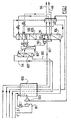
- FIG. 1 is a diagram of an apparatus according to the prior art
- FIG. 2 is a device diagram according to the invention.
- an air flow rate of 5.25 bar is divided in two to form a flow 2 of 188135 Nm3 / h and a flow 81 of 12900 Nm3 / h.
- Flow 2 is cools in exchanger 100 and is sent to the middle column vessel pressure 104.
- the flow 81 is boosted to 8.7 bars, cooled partially in the exchanger 100 and relaxed in the insufflation turbine 103 before being sent in low pressure column 105.
- the medium pressure column 104 operates at 5 bar and the low column pressure 105 operates at 1.3 bar.
- the columns are thermally connected by a first condenser vaporizer 111.
- the apparatus produces liquid oxygen 46 and liquid nitrogen 36.
- rich liquid from the medium pressure column 104 is sent to the column low pressure 105 above the level of insufflation air.
- Liquid oxygen 50 withdrawn into the bottom of the low pressure column is sent to the top of the mixing column 107 after being pumped to 5.1 bars.
- a third air flow 90 cools completely in the exchanger 100 and feeds the mixing column into the tank.
- a tank liquid 93 and optionally at least one intermediate liquid withdrawn from the column of mixture are sent to the low pressure column while a flow of oxygen containing 54 to 95 mol% oxygen is withdrawn at the top of the mixing column and warms up in exchanger 100 with 3100 Nm3 / h of medium nitrogen pressure and the low pressure residual.
- the rich liquid 18 sent to the second vaporizer-condenser 109 constitutes 37% of the total flow of rich liquid and vaporizes in that one for then be sent to the low pressure column a few theoretical plateaus above the first vaporizer-condenser 111.
- the apparatus may comprise an argon column or a pressure column intermediate between the medium and low pressures.
- the frigories necessary for the apparatus can be produced by a Claude turbine or a nitrogen turbine or a combination of several turbines.
- the low pressure column can contain at least two vaporizers condensers, the vessel vaporizer being supplied for example with nitrogen compressed.
- the mixing column can operate at equal pressure, higher or less than average pressure.
- a liquid coming from the apparatus and rich in nitrogen or oxygen can be pressurized, for example by a pump, and vaporized in the exchanger 100 or another exchanger, for example by heat exchange with air for supply a gaseous product under pressure.
- the low pressure column can operate at a pressure between 1.5 and 10 bars. To produce oxygen directly under pressure, the column low pressure operates at between 4 and 10 bar.
- Some of the air from the insufflation turbine can be sent to the mixing column.
- the medium and low pressure columns can be built side by side side.
- the process can allow gaseous oxygen production by drawing off a flow of gaseous oxygen in the bottom of the low pressure column.
- the gas heats in the exchanger 100 and can optionally be compressed once warmed.
Description
L'invention proposée ici est relative au domaine de la distillation des gaz de l'air et en particulier à un appareil et procède de séparation d'air par distillation cryogénique. Elle permet d'améliorer le rendement d'extraction d'oxygène et ainsi les performances énergétiques sur les schémas de distillation ne comportant pas ordinairement d'alimentation d'air liquéfié dans les colonnes et dont la production frigorifique est assurée par une détente d'air (turbine à frein d'huile, génératrice ou auto-boostée). Les gains de cette invention lorsqu'elle est implantée sur une unité de séparation d'air sont de 3.5% (cf. cas présenté ci-dessous) en énergie de séparation de l'oxygène.The invention proposed here relates to the field of gas distillation air and especially to a device and proceeds from air separation by cryogenic distillation. It improves the extraction efficiency of oxygen and so the energy performance on the patterns of distillation which does not ordinarily include a supply of liquefied air columns and whose cooling production is ensured by an air release (oil brake turbine, generator or auto-boosted). The gains of this invention when it is implanted on an air separation unit are of 3.5% (see case below) in oxygen separation energy.
Ceci constitue une avancée importante dans un domaine déjà bien exploré où les gains supérieurs à 1% sont les bienvenus notamment dans les pays où le coût de l'énergie est important.This is an important step forward in a field already well explored where earnings above 1% are welcome especially in countries where the cost of energy is important.
Les procédés de distillation de base sur lesquels l'invention peut être utilisée, sont des procédés qui ne comportent pas ordinairement d'alimentation d'air liquide dans les colonnes de distillation.The basic distillation processes on which the invention can be used, are processes that do not ordinarily involve feeding of liquid air in the distillation columns.
Ces procédés de base sont des procédés de séparation des gaz de l'air avec compression d'air, pré refroidissement d'air comprimé, épuration d'air, refroidissement d'air dans un échangeur principal, séparation d'air dans une colonne de distillation comprenant au moins une colonne moyenne pression et une colonne basse pression et sous-refroidissement des liquides venant en reflux de la colonne moyenne pression vers la colonne basse pression.These basic processes are processes for separating gases from the air with air compression, pre-cooling of compressed air, air cleaning, cooling of air in a main exchanger, separation of air in a distillation column comprising at least one medium pressure column and a column low pressure and subcooling liquids coming in reflux of the medium pressure column to the low pressure column.
Parmi les schémas concernés, nous pouvons citer :Among the schemes concerned, we can mention:
Un cas d'application : production d'oxygène impur avec colonne moyenne pression MP et basse pression BP sous pression (valorisation du résiduaire). Dans ce cas, la perte de rendement due à la baisse de reflux (distillation plus difficile dans la colonne MP) se fait cruellement sentir. Cette invention permettra d'améliorer le rendement dans ce cas. An application case: production of impure oxygen with medium pressure MP column and low pressure BP under pressure (recovery of the waste). In this case, the loss of efficiency due to the reflux decline (more difficult distillation in the MP column) is sorely feel. This invention will improve the efficiency in this case.
Sur ce type de schéma produisant de l'oxygène directement sous pression (5 bars par exemple) en ne mettant que le minimum d'énergie dans l'appareil (par rapport à un schéma à pompe), on atteint pour un rendement de 99 % O2, une production de 1.1 % d'azote MP (une caractérisation possible de la surpuissance de rectification en azote gazeux moyenne pression) (turbine d'insufflation, 2000 t/j, oxygène à 95 % et 5 bars, nombre important de plateaux).On this type of scheme producing oxygen directly under pressure (5 bars for example) by putting only the minimum energy in the device (compared to a pump diagram), one achieves for a performance of 99% O2, a production of 1.1% nitrogen MP (a possible characterization of the overheating rectification in medium pressure nitrogen gas) (turbine insufflation, 2000 t / d, 95% oxygen and 5 bar, a large number of plateaus).
Pour des tailles d'appareil plus petites, le rendement de 99 % ne peut plus être atteint. Là encore, un gain en rendement est obtenu avec cette invention.For smaller device sizes, the 99% efficiency can not no longer be reached. Again, a gain in yield is obtained with this invention.
Sur ces deux schémas, nous allons pouvoir ainsi augmenter les rendements d'oxygène (ou la quantité d'azote moyenne pression produite si le rendement d'oxygène est déjà haut) et ainsi améliorer les performances énergétiques de l'unité de séparation d'air. Ceci conduit bien sûr à faire des économies d'argent importantes.On these two schemes, we will be able to increase oxygen yields (or the amount of medium pressure nitrogen produced if the oxygen yield is already high) and thus improve performance energy of the air separation unit. This of course leads to significant savings.
Il est connu de EP-A-0556516 de condenser un débit d'air provenant d'une turbine d'insufflation dans un vaporiseur condenseur, soit à un niveau intermédiaire de la colonne basse pression, soit alimenté par un liquide provenant de la colonne moyenne pression ou de la colonne basse pression. L'air ainsi liquéfié est envoyé à la colonne basse pression mais ne constitue pas le seul apport d'air liquide à l'appareil puisque de l'air est également liquéfié dans le condenseur de cuve de l'appareil et envoyé aux deux colonnes de la double colonne.It is known from EP-A-0556516 to condense a flow of air from of a blowing turbine in a condenser vaporizer, ie at a level intermediate of the low pressure column, is fed by a liquid from the medium pressure column or the low pressure column. The air thus liquefied is sent to the low pressure column but does not constitute not the only supply of liquid air to the device since air is also liquefied in the cell condenser of the apparatus and sent to both columns double column.
EP-A-0381319 décrit un système de colonnes dans lequel un débit d'air se vaporise contre un débit contenant 95 vol.% d'oxygène.EP-A-0381319 discloses a column system in which an air flow rate vaporizes against a flow containing 95 vol.% oxygen.
US-A-5765396 concerne un procédé à pompe classique dans lequel un débit d'air se condense contre du liquide contenant entre 98 et 100 mol.%.US-A-5765396 relates to a conventional pump process in which a air flow condenses against liquid containing between 98 and 100 mol%.
US-A-5582035 et US-A-5291737 divulguent des procédés de séparation d'air avec colonne de mélange dans lequel tout l'air rentre dans les colonnes sous forme gazeuse. US-A-5582035 and US-A-5291737 disclose separation methods of air with mixing column in which all the air enters the columns in gaseous form.
US-A-3754406 propose de vaporiser du liquide riche de la colonne moyenne pression d'une double colonne contre de l'azote gazeux moyenne pression. De l'air est liquéfié par échange de chaleur avec de l'oxygène liquide pompé et envoyé à la colonne basse pression.US-A-3754406 proposes to vaporize rich liquid from the column medium pressure of a double column against medium nitrogen gas pressure. Air is liquefied by heat exchange with liquid oxygen pumped and sent to the low pressure column.
Selon un objet de l'invention, il est prévu un appareil de séparation d'air selon la revendication 1.According to an object of the invention, there is provided an air separation apparatus according to claim 1.
Optionnellement l'air au moins partiellement condensé envoyé à la colonne basse pression constitue le seul débit d'air liquéfié envoyé au système de colonnes.Optionally at least partially condensed air sent to the Low pressure column is the only flow of liquefied air to the system of columns.
De préférence, l'appareil comprend des moyens pour détendre l'air avec production de travail avant de l'envoyer au deuxième vaporiseur-condenseur et /ou des moyens pour refroidir l'air à son point de rosée avant de l'envoyer au deuxième vaporiseur-condenseur.Preferably, the apparatus comprises means for relaxing the air with production work before sending it to the second vaporizer-condenser and / or means to cool the air to its dew point before sending it to second vaporizer-condenser.
L'air au moins partiellement condensé peut être envoyé à la colonne basse pression et/ou à la colonne moyenne pression et/ou à une autre colonne du système de colonnes.At least partially condensed air can be sent to the column low pressure and / or medium pressure column and / or other column of the column system.
Préférablement, l'appareil comprend une colonne de mélange alimentée en tête par un liquide riche en oxygène provenant de la colonne basse pression et alimentée en cuve par un gaz plus volatil que le liquide riche en oxygène.Preferably, the apparatus comprises a powered mixing column at the top by a rich oxygen liquid from the column tank-fed by a more volatile gas than the liquid rich in oxygen.
Il peut y avoir des moyens pour soutirer un gaz riche en azote en tête de la colonne moyenne pression.There may be ways to extract a nitrogen-rich gas at the top of the medium pressure column.
De préférence, la colonne basse pression n'a pas de condenseur de tête.Preferably, the low pressure column has no overhead condenser.
Selon un autre objet de l'invention, il est prévu un procédé de séparation selon la revendication 7. According to another object of the invention, there is provided a separation process according to claim 7.
Selon d'autres aspects facultatifs :
- on détend le deuxième débit dans une turbine avant d'en envoyer au moins une partie au deuxième vaporiseur-condenseur ;
- on envoie un liquide riche en oxygène de la colonne basse pression en tête d'une colonne de mélange et on envoie un gaz plus volatil que le liquide en cuve de la colonne de mélange, par exemple de l'air ;
- on soutire de l'azote en tête de la colonne moyenne pression ;
- the second flow rate is expanded in a turbine before sending at least a portion to the second vaporizer-condenser;
- an oxygen-rich liquid is sent from the low pressure column to the top of a mixing column and a more volatile gas is sent than the liquid in the tank of the mixing column, for example air;
- Nitrogen is withdrawn at the top of the medium pressure column;
De l'air gazeux sortant d'une turbine peut être condensé dans le deuxième vaporiseur/condenseur contre une partie du liquide riche sortant de la MP. Cette fraction de ce dernier se vaporise à la pression de la BP et est introduite ensuite en BP dans un tronçon sous l'alimentation en liquide riche principale. L'air liquéfié est, quant à lui, introduit, par exemple, dans la BP à un tronçon intermédiaire entre le liquide riche et le liquide pauvre. (cf. schémas ci-joint).Gaseous air coming out of a turbine can be condensed into the second vaporizer / condenser against a part of the rich liquid coming out of the MP. This fraction of the latter vaporizes at the pressure of the BP and is then introduced into BP in a section under the rich liquid supply main. The liquefied air is, for its part, introduced, for example, in the BP to a Intermediate section between the rich liquid and the poor liquid. (see diagram attached).
L'avantage déterminant de l'ajout de ce deuxième vaporiseur/condenseur est qu'il crée en distillant une partie du liquide riche, de l'air liquide qui vient assurer le reflux dans le tronçon supérieur de la BP en complément du liquide pauvre. Le diagramme de distillation en BP se trouve ainsi amélioré. Même s'il y a moins d'air qui alimente la MP à cause d'une augmentation du débit d'insufflation (taux de détente plus faible), l'effet global va dans le sens d'une amélioration de la puissance de rectification.The decisive advantage of adding this second vaporizer / condenser is that it creates by distilling some of the rich liquid, liquid air that comes ensure the reflux in the upper section of the BP in addition to the liquid poor. The distillation diagram in BP is thus improved. Even if he there is less air that feeds the MP due to increased flow insufflation (lower relaxation rate), the overall effect is in line with improvement of the grinding power.
L'invention sera maintenant décrite en plus de détail en se référant aux figures suivantes :The invention will now be described in more detail with reference to the following figures:
La figure 1 est un schéma d'un appareil selon l'art antérieur, la figure 2 est un schéma d'appareil selon l'invention.FIG. 1 is a diagram of an apparatus according to the prior art, FIG. 2 is a device diagram according to the invention.
Dans la figure 1, un débit d'air à 5,25 bars est divisé en deux pour former
un débit 2 de 188135 Nm3/h et un débit 81 de 12900 Nm3 /h. Le débit 2 se
refroidit dans l'échangeur 100 et est envoyé à la cuve de la colonne moyenne
pression 104. Le débit 81 est surpressé à 8,7 bars, refroidi partiellement dans
l'échangeur 100 et détendu dans la turbine d'insufflation 103 avant d'être
envoyé en colonne basse pression 105.In Figure 1, an air flow rate of 5.25 bar is divided in two to form
a flow 2 of 188135 Nm3 / h and a
La colonne moyenne pression 104 opère à 5 bars et la colonne basse
pression 105 opère à 1,3 bar. Les colonnes sont reliées thermiquement par un
premier vaporiseur condenseur 111.The
L'appareil produit de l'oxygène liquide 46 et de l'azote liquide 36. Le
liquide riche de la colonne moyenne pression 104 est envoyé à la colonne
basse pression 105 au-dessus du niveau d'air d'insufflation.The apparatus produces
De l'oxygène liquide 50 soutiré en cuve de la colonne basse pression est
envoyé en tête de la colonne de mélange 107 après être pompé à 5,1 bars. Un
troisième débit d'air 90 se refroidit complètement dans l'échangeur 100 et
alimente la colonne de mélange en cuve. Un liquide de cuve 93 et
éventuellement au moins un liquide intermédiaire soutirés de la colonne de
mélange sont envoyés à la colonne basse pression alors qu'un débit d'oxygène
contenant 54 à 95 mol % d'oxygène est soutiré en tête de colonne de mélange
et se réchauffe dans l'échangeur 100 avec 3100 Nm3/h d'azote moyenne
pression et le résiduaire basse pression.
Dans la figure 2, on retrouve les mêmes colonne et échangeurs alimentés
de la même façon sauf que tout l'air 86 de la turbine d'insufflation est envoyé
au deuxième vaporiseur-condenseur 109 où il se condense contre une partie
du liquide riche 18 qui s'y vaporise au moins partiellement. L'air liquéfié est
détendu dans une vanne et envoyé à la colonne basse pression quelques
plateaux en dessus du point d'injection de liquide pauvre provenant de la
colonne basse pression.In Figure 2, we find the same column and exchangers powered
in the same way except that all the
Le liquide riche 18 envoyé au deuxième vaporiseur-condenseur 109
constitue 37% du débit total de liquide riche et se vaporise dans celui-là pour
être ensuite envoyé à la colonne basse pression quelques plateaux théoriques
au-dessus du premier vaporiseur-condenseur 111.The
Ceci permet de soutirer 11400 Nm3/h d'azote gazeux moyenne pression
30.
Figure 1
(Figure 2)
Figure 1
(Figure 2)
L'appareil peut comprendre une colonne argon ou une colonne à pression intermédiaire entre les moyenne et basse pressions.The apparatus may comprise an argon column or a pressure column intermediate between the medium and low pressures.
Les frigories nécessaires à l'appareil peuvent être produites par une turbine Claude ou une turbine d'azote ou par une combinaison de plusieurs turbines. The frigories necessary for the apparatus can be produced by a Claude turbine or a nitrogen turbine or a combination of several turbines.
La colonne basse pression peut contenir au moins deux vaporiseur condenseurs, le vaporiseur de cuve étant alimenté par exemple par de l'azote comprimé.The low pressure column can contain at least two vaporizers condensers, the vessel vaporizer being supplied for example with nitrogen compressed.
La colonne de mélange peut opérer à une pression égale, supérieure ou inférieure à la moyenne pression.The mixing column can operate at equal pressure, higher or less than average pressure.
Un liquide provenant de l'appareil et riche en azote ou oxygène peut être
pressurisé, par exemple par une pompe, et vaporisé dans l'échangeur 100 ou
un autre échangeur, par exemple par échange de chaleur avec de l'air pour
fournir un produit gazeux sous pression.A liquid coming from the apparatus and rich in nitrogen or oxygen can be
pressurized, for example by a pump, and vaporized in the
La colonne basse pression peut opérer à une pression entre 1,5 et 10 bars. Pour produire l'oxygène directement sous pression, la colonne basse pression opère à entre 4 et 10 bars.The low pressure column can operate at a pressure between 1.5 and 10 bars. To produce oxygen directly under pressure, the column low pressure operates at between 4 and 10 bar.
Une partie de l'air de la turbine d'insufflation peut être envoyée à la colonne de mélange.Some of the air from the insufflation turbine can be sent to the mixing column.
Les colonnes moyenne et basse pression peuvent être construites côte à côte.The medium and low pressure columns can be built side by side side.
Le procédé peut permettre une production d'oxygène gazeux en soutirant
un débit d'oxygène gazeux en cuve de la colonne basse pression. Le gaz se
réchauffe dans l'échangeur 100 et peut éventuellement être comprimé une fois
réchauffé.The process can allow gaseous oxygen production by drawing off
a flow of gaseous oxygen in the bottom of the low pressure column. The gas
heats in the
Claims (13)
- Air separation apparatus comprising a column system comprising at least one double column comprising a medium-pressure column (104) and a low-pressure column (105) which are thermally linked to each other by a first reboiler/condenser (111) where the gas at the top of the medium-pressure column condenses, means for sending compressed and purified air to a heat exchanger (100) where it cools, means (2) for sending cooled air to the medium-pressure column in gas form, means for sending an oxygen-enriched fluid from the medium-pressure column to the low-pressure column where it is separated by cryogenic distillation, means for sending a nitrogen-enriched fluid from the medium-pressure column to the low-pressure column, means for withdrawing a nitrogen-rich fluid and an oxygen-rich fluid from the low-pressure column, a second reboiler/condenser (109), means (86) for sending air to the second reboiler/condenser where it condenses at least partially, and means for sending the at least partially condensed air to the low-pressure column, and the at least partially condensed air sent to the low-pressure column (104) comprising the only stream of liquefied air sent to the column system, the liquid sent to the second reboiler/condenser coming. from the medium-pressure column, the apparatus including means for sending a portion of the liquid from the bottom of the medium-pressure column (104) directly to the low-pressure column (105) at a first level and another portion (18) of the liquid from the bottom of the medium-pressure column to the second reboiler/condenser (109), and means for sending the liquid vaporized in the second reboiler/condenser to the low-pressure column at a level below the first level, the liquid (18) sent to the second reboiler/condenser containing between 22 and 70 mol%, optionally between 22 and 35 mol% of oxygen.
- Apparatus according to Claim 1, which includes means (103) for expanding the air with production of work before sending it to the second reboiler/condenser (109).
- Apparatus according to either of the preceding claims, which includes means for cooling the air to its dew point before sending it to the second reboiler/condenser (109).
- Apparatus according to one of the preceding claims, which includes a mixing column (107) fed at the top with an oxygen-rich liquid (50) coming from the low-pressure column and fed at the bottom with a gas (90) more volatile than the oxygen-rich liquid.
- Apparatus according to one of the preceding claims, which includes means (30) for withdrawing a nitrogen-rich gas from the top of the medium-pressure column.
- Apparatus according to one of the preceding claims, in which the low-pressure column does not have a top condenser.
- Process for separating air by cryogenic distillation in an apparatus comprising at least one double column with a medium-pressure column (104) and a low-pressure column (105) which are thermally linked to each other by a first reboiler/condenser (111), in which process a stream of purified, compressed and cooled air (2) is sent to the medium-pressure column, in gas form, an oxygen-enriched fluid is sent from the medium-pressure column to the low-pressure column, where it is separated by cryogenic distillation, a nitrogen-enriched fluid is sent from the medium-pressure column to the low-pressure column, an oxygen-rich fluid and a nitrogen-rich fluid are withdrawn from the low-pressure column, a second stream of purified, compressed and cooled air (86) is sent to a second reboiler/condenser (109) where it condenses, at least partially, by heat exchange with a liquid (18) coming from the medium-pressure column (104), the at least partially condensed air is sent to the low-pressure column, the liquid (18) sent to the second reboiler/condenser containing between 22 and 70 mol% oxygen, optionally between 22 and 35 mol% oxygen, the air liquefied in the second reboiler/condenser constituting the only stream of liquefied air sent to the column system, a portion of the liquid from the bottom of the medium-pressure column being sent directly to the low-pressure column at a first level, another portion of the bottom liquid being sent to the second reboiler/condenser, where it is vaporizes, and the vaporized liquid being sent to the low-pressure column at a level below the first level.
- Process according to Claim 7, in which the second stream is expanded in a turbine (103) before at least one portion thereof is sent to the second reboiler/condenser (109).
- Process according to Claim 7 or 8, in which an oxygen-rich liquid (50) is sent from the low-pressure column to the top of a mixing column (107) and a gas (90) more volatile than the oxygen-rich liquid is sent to the bottom of the mixing column (107).
- Process according to Claim 7, 8 or 9, in which nitrogen (30) is sent, optionally in gas form, to the top of the medium-pressure column (104).
- Process according to one of Claims 7 to 10, in which a liquid and/or a gas rich in oxygen are/is withdrawn from the bottom of the low-pressure column, optionally as product(s).
- Process according to one of Claims 7 to 11, in which the low-pressure column operates at between 1.5 and 10 bar absolute, optionally between 3 and 10 bar absolute.
- Process according to one of Claims 7 to 12, in which the gas at the top of the low-pressure column (105) does not condense in a condenser.
Applications Claiming Priority (2)
| Application Number | Priority Date | Filing Date | Title |
|---|---|---|---|
| FR9907931 | 1999-06-22 | ||
| FR9907931A FR2795496B1 (en) | 1999-06-22 | 1999-06-22 | APPARATUS AND METHOD FOR SEPARATING AIR BY CRYOGENIC DISTILLATION |
Publications (2)
| Publication Number | Publication Date |
|---|---|
| EP1063485A1 EP1063485A1 (en) | 2000-12-27 |
| EP1063485B1 true EP1063485B1 (en) | 2005-04-06 |
Family
ID=9547139
Family Applications (1)
| Application Number | Title | Priority Date | Filing Date |
|---|---|---|---|
| EP00401768A Expired - Lifetime EP1063485B1 (en) | 1999-06-22 | 2000-06-21 | Device and process for air separation by cryogenic distillation |
Country Status (4)
| Country | Link |
|---|---|
| US (1) | US6339938B1 (en) |
| EP (1) | EP1063485B1 (en) |
| DE (1) | DE60019198T2 (en) |
| FR (1) | FR2795496B1 (en) |
Families Citing this family (4)
| Publication number | Priority date | Publication date | Assignee | Title |
|---|---|---|---|---|
| FR2830928B1 (en) * | 2001-10-17 | 2004-03-05 | Air Liquide | PROCESS FOR SEPARATING AIR BY CRYOGENIC DISTILLATION AND AN INSTALLATION FOR CARRYING OUT SAID METHOD |
| US7296437B2 (en) * | 2002-10-08 | 2007-11-20 | L'air Liquide, Societe Anonyme A Directoire Et Conseil De Surveillance Pour L'etude Et L'exploitation Des Procedes Georges Claude | Process for separating air by cryogenic distillation and installation for implementing this process |
| GB0422635D0 (en) * | 2004-10-12 | 2004-11-10 | Air Prod & Chem | Process for the cryogenic distillation of air |
| FR2930629B1 (en) * | 2008-04-23 | 2010-05-07 | Air Liquide | APPARATUS AND METHOD FOR AIR SEPARATION BY CRYOGENIC DISTILLATION |
Citations (1)
| Publication number | Priority date | Publication date | Assignee | Title |
|---|---|---|---|---|
| EP0682219A1 (en) * | 1994-05-10 | 1995-11-15 | Praxair Technology, Inc. | Air boiling cryogenic rectification system for producing elevated pressure oxygen |
Family Cites Families (5)
| Publication number | Priority date | Publication date | Assignee | Title |
|---|---|---|---|---|
| US4895583A (en) * | 1989-01-12 | 1990-01-23 | The Boc Group, Inc. | Apparatus and method for separating air |
| FR2680114B1 (en) * | 1991-08-07 | 1994-08-05 | Lair Liquide | METHOD AND INSTALLATION FOR AIR DISTILLATION, AND APPLICATION TO THE GAS SUPPLY OF A STEEL. |
| US5257504A (en) * | 1992-02-18 | 1993-11-02 | Air Products And Chemicals, Inc. | Multiple reboiler, double column, elevated pressure air separation cycles and their integration with gas turbines |
| EP0636845B1 (en) * | 1993-04-30 | 1999-07-28 | The BOC Group plc | Air separation |
| US5765396A (en) * | 1997-03-19 | 1998-06-16 | Praxair Technology, Inc. | Cryogenic rectification system for producing high pressure nitrogen and high pressure oxygen |
-
1999
- 1999-06-22 FR FR9907931A patent/FR2795496B1/en not_active Expired - Fee Related
-
2000
- 2000-06-21 EP EP00401768A patent/EP1063485B1/en not_active Expired - Lifetime
- 2000-06-21 DE DE60019198T patent/DE60019198T2/en not_active Expired - Fee Related
- 2000-06-22 US US09/599,407 patent/US6339938B1/en not_active Expired - Fee Related
Patent Citations (1)
| Publication number | Priority date | Publication date | Assignee | Title |
|---|---|---|---|---|
| EP0682219A1 (en) * | 1994-05-10 | 1995-11-15 | Praxair Technology, Inc. | Air boiling cryogenic rectification system for producing elevated pressure oxygen |
Also Published As
| Publication number | Publication date |
|---|---|
| FR2795496B1 (en) | 2001-08-03 |
| DE60019198D1 (en) | 2005-05-12 |
| US6339938B1 (en) | 2002-01-22 |
| DE60019198T2 (en) | 2006-03-09 |
| FR2795496A1 (en) | 2000-12-29 |
| EP1063485A1 (en) | 2000-12-27 |
Similar Documents
| Publication | Publication Date | Title |
|---|---|---|
| EP0713069B1 (en) | Process and plant for air separation | |
| EP1623172A1 (en) | Method and system for the production of pressurized air gas by cryogenic distillation of air | |
| EP1189003B1 (en) | Process and apparatus for air separation by cryogenic distillation | |
| EP1143216B1 (en) | Process and apparatus for the production of oxygen enriched fluid by cryogenic distillation | |
| JP2000310481A (en) | Method and device for separating cryogenic air | |
| FR2949846A1 (en) | PROCESS AND PLANT FOR PRODUCING OXYGEN BY AIR DISTILLATION | |
| EP1063485B1 (en) | Device and process for air separation by cryogenic distillation | |
| CA2830826A1 (en) | Method and device for separating air by cryogenic distillation | |
| EP3069091A2 (en) | Process and apparatus for separating air by cryogenic distillation | |
| EP3058297B1 (en) | Method and device for separating air by cryogenic distillation | |
| EP0699884A1 (en) | Process and installation for the production of oxygen by cryogenic destillation | |
| EP1106945B1 (en) | Process for air separation by cryogenic distillation | |
| EP1132700B1 (en) | Process and apparatus for air separation by cryogenic distillation | |
| US20040244416A1 (en) | Method for separating air by cryogenic distillation and installation therefor | |
| FR2787559A1 (en) | Air separation using cryogenic distillation has double column receiving compressed, cooled, and expanded air to produce oxygen rich and nitrogen rich fractions | |
| FR2787561A1 (en) | Cryogenic distillation of air uses double column with air supply to medium pressure column and oxygen rich fluid from bottom of both low pressure and auxiliary columns | |
| FR2972794A1 (en) | APPARATUS AND METHOD FOR AIR SEPARATION BY CRYOGENIC DISTILLATION | |
| FR2819046A1 (en) | Cryogenic distillation air separation plant uses compressor to compress nitrogen-rich flow with inlet temperature below that of heat exchanger | |
| EP3913310A1 (en) | Method and device for air separation by cryogenic distilling | |
| FR2861841A1 (en) | METHOD AND APPARATUS FOR AIR SEPARATION BY CRYOGENIC DISTILLATION | |
| FR2974890A1 (en) | Method for separating air by cryogenic distillation in installation, involves condensing part of nitrogen enriched gas flow before being sent to average pressure column and/or low pressure column, and heating gas flow rich in oxygen | |
| FR2854232A1 (en) | Air separation procedure to produce argon uses cryogenic distillation with additional liquid flow containing 18-30 mol percent oxygen fed to low pressure column | |
| FR2874249A1 (en) | Air separation by cryogenic distillation using medium and low pressure columns, for production of oxygen and/or nitrogen, with residual stream extracted from low pressure column to maintain product purity |
Legal Events
| Date | Code | Title | Description |
|---|---|---|---|
| PUAI | Public reference made under article 153(3) epc to a published international application that has entered the european phase |
Free format text: ORIGINAL CODE: 0009012 |
|
| AK | Designated contracting states |
Kind code of ref document: A1 Designated state(s): DE FR GB |
|
| AX | Request for extension of the european patent |
Free format text: AL;LT;LV;MK;RO;SI |
|
| 17P | Request for examination filed |
Effective date: 20010627 |
|
| AKX | Designation fees paid |
Free format text: DE FR GB |
|
| RAP1 | Party data changed (applicant data changed or rights of an application transferred) |
Owner name: L'AIR LIQUIDE, S.A. A DIRECTOIRE ET CONSEIL DE SUR |
|
| 17Q | First examination report despatched |
Effective date: 20030319 |
|
| GRAP | Despatch of communication of intention to grant a patent |
Free format text: ORIGINAL CODE: EPIDOSNIGR1 |
|
| RIN1 | Information on inventor provided before grant (corrected) |
Inventor name: DE BUSSY, FRANEOIS Inventor name: JUDAS, FREDERIC |
|
| GRAS | Grant fee paid |
Free format text: ORIGINAL CODE: EPIDOSNIGR3 |
|
| GRAA | (expected) grant |
Free format text: ORIGINAL CODE: 0009210 |
|
| AK | Designated contracting states |
Kind code of ref document: B1 Designated state(s): DE FR GB |
|
| REG | Reference to a national code |
Ref country code: GB Ref legal event code: FG4D Free format text: NOT ENGLISH |
|
| REF | Corresponds to: |
Ref document number: 60019198 Country of ref document: DE Date of ref document: 20050512 Kind code of ref document: P |
|
| GBT | Gb: translation of ep patent filed (gb section 77(6)(a)/1977) |
Effective date: 20050719 |
|
| PLBE | No opposition filed within time limit |
Free format text: ORIGINAL CODE: 0009261 |
|
| STAA | Information on the status of an ep patent application or granted ep patent |
Free format text: STATUS: NO OPPOSITION FILED WITHIN TIME LIMIT |
|
| 26N | No opposition filed |
Effective date: 20060110 |
|
| PGFP | Annual fee paid to national office [announced via postgrant information from national office to epo] |
Ref country code: DE Payment date: 20080523 Year of fee payment: 9 |
|
| PGFP | Annual fee paid to national office [announced via postgrant information from national office to epo] |
Ref country code: GB Payment date: 20080521 Year of fee payment: 9 |
|
| GBPC | Gb: european patent ceased through non-payment of renewal fee |
Effective date: 20090621 |
|
| REG | Reference to a national code |
Ref country code: FR Ref legal event code: ST Effective date: 20100226 |
|
| PG25 | Lapsed in a contracting state [announced via postgrant information from national office to epo] |
Ref country code: FR Free format text: LAPSE BECAUSE OF NON-PAYMENT OF DUE FEES Effective date: 20090630 |
|
| PGFP | Annual fee paid to national office [announced via postgrant information from national office to epo] |
Ref country code: FR Payment date: 20080513 Year of fee payment: 9 |
|
| PG25 | Lapsed in a contracting state [announced via postgrant information from national office to epo] |
Ref country code: GB Free format text: LAPSE BECAUSE OF NON-PAYMENT OF DUE FEES Effective date: 20090621 |
|
| PG25 | Lapsed in a contracting state [announced via postgrant information from national office to epo] |
Ref country code: DE Free format text: LAPSE BECAUSE OF NON-PAYMENT OF DUE FEES Effective date: 20100101 |