EP1063125B1 - Stellantrieb für ein Kraftfahrzeug - Google Patents
Stellantrieb für ein Kraftfahrzeug Download PDFInfo
- Publication number
- EP1063125B1 EP1063125B1 EP00108886A EP00108886A EP1063125B1 EP 1063125 B1 EP1063125 B1 EP 1063125B1 EP 00108886 A EP00108886 A EP 00108886A EP 00108886 A EP00108886 A EP 00108886A EP 1063125 B1 EP1063125 B1 EP 1063125B1
- Authority
- EP
- European Patent Office
- Prior art keywords
- friction
- actuator according
- displacement
- connexion
- members
- Prior art date
- Legal status (The legal status is an assumption and is not a legal conclusion. Google has not performed a legal analysis and makes no representation as to the accuracy of the status listed.)
- Expired - Lifetime
Links
- 238000006073 displacement reaction Methods 0.000 claims description 41
- 229910052751 metal Inorganic materials 0.000 claims description 7
- 239000002184 metal Substances 0.000 claims description 7
- 238000005452 bending Methods 0.000 claims description 2
- 239000002131 composite material Substances 0.000 claims description 2
- 239000000463 material Substances 0.000 claims description 2
- 230000000284 resting effect Effects 0.000 claims 2
- 230000000694 effects Effects 0.000 description 3
- 229910052782 aluminium Inorganic materials 0.000 description 2
- XAGFODPZIPBFFR-UHFFFAOYSA-N aluminium Chemical compound [Al] XAGFODPZIPBFFR-UHFFFAOYSA-N 0.000 description 2
- 238000013016 damping Methods 0.000 description 2
- 238000004519 manufacturing process Methods 0.000 description 2
- 238000004080 punching Methods 0.000 description 2
- FYYHWMGAXLPEAU-UHFFFAOYSA-N Magnesium Chemical compound [Mg] FYYHWMGAXLPEAU-UHFFFAOYSA-N 0.000 description 1
- AZDRQVAHHNSJOQ-UHFFFAOYSA-N alumane Chemical group [AlH3] AZDRQVAHHNSJOQ-UHFFFAOYSA-N 0.000 description 1
- 230000009286 beneficial effect Effects 0.000 description 1
- 230000005540 biological transmission Effects 0.000 description 1
- 230000015572 biosynthetic process Effects 0.000 description 1
- 238000010276 construction Methods 0.000 description 1
- 230000008878 coupling Effects 0.000 description 1
- 238000010168 coupling process Methods 0.000 description 1
- 238000005859 coupling reaction Methods 0.000 description 1
- 238000001514 detection method Methods 0.000 description 1
- 239000011521 glass Substances 0.000 description 1
- 229910052749 magnesium Inorganic materials 0.000 description 1
- 239000011777 magnesium Substances 0.000 description 1
Images




Classifications
-
- B—PERFORMING OPERATIONS; TRANSPORTING
- B60—VEHICLES IN GENERAL
- B60R—VEHICLES, VEHICLE FITTINGS, OR VEHICLE PARTS, NOT OTHERWISE PROVIDED FOR
- B60R1/00—Optical viewing arrangements; Real-time viewing arrangements for drivers or passengers using optical image capturing systems, e.g. cameras or video systems specially adapted for use in or on vehicles
- B60R1/02—Rear-view mirror arrangements
- B60R1/06—Rear-view mirror arrangements mounted on vehicle exterior
- B60R1/062—Rear-view mirror arrangements mounted on vehicle exterior with remote control for adjusting position
- B60R1/07—Rear-view mirror arrangements mounted on vehicle exterior with remote control for adjusting position by electrically powered actuators
- B60R1/072—Rear-view mirror arrangements mounted on vehicle exterior with remote control for adjusting position by electrically powered actuators for adjusting the mirror relative to its housing
-
- Y—GENERAL TAGGING OF NEW TECHNOLOGICAL DEVELOPMENTS; GENERAL TAGGING OF CROSS-SECTIONAL TECHNOLOGIES SPANNING OVER SEVERAL SECTIONS OF THE IPC; TECHNICAL SUBJECTS COVERED BY FORMER USPC CROSS-REFERENCE ART COLLECTIONS [XRACs] AND DIGESTS
- Y10—TECHNICAL SUBJECTS COVERED BY FORMER USPC
- Y10T—TECHNICAL SUBJECTS COVERED BY FORMER US CLASSIFICATION
- Y10T74/00—Machine element or mechanism
- Y10T74/18—Mechanical movements
- Y10T74/18568—Reciprocating or oscillating to or from alternating rotary
- Y10T74/188—Reciprocating or oscillating to or from alternating rotary including spur gear
- Y10T74/18808—Reciprocating or oscillating to or from alternating rotary including spur gear with rack
- Y10T74/18816—Curvilinear rack
-
- Y—GENERAL TAGGING OF NEW TECHNOLOGICAL DEVELOPMENTS; GENERAL TAGGING OF CROSS-SECTIONAL TECHNOLOGIES SPANNING OVER SEVERAL SECTIONS OF THE IPC; TECHNICAL SUBJECTS COVERED BY FORMER USPC CROSS-REFERENCE ART COLLECTIONS [XRACs] AND DIGESTS
- Y10—TECHNICAL SUBJECTS COVERED BY FORMER USPC
- Y10T—TECHNICAL SUBJECTS COVERED BY FORMER US CLASSIFICATION
- Y10T74/00—Machine element or mechanism
- Y10T74/18—Mechanical movements
- Y10T74/18568—Reciprocating or oscillating to or from alternating rotary
- Y10T74/188—Reciprocating or oscillating to or from alternating rotary including spur gear
- Y10T74/18808—Reciprocating or oscillating to or from alternating rotary including spur gear with rack
- Y10T74/18816—Curvilinear rack
- Y10T74/18824—Curvilinear rack with biasing means
-
- Y—GENERAL TAGGING OF NEW TECHNOLOGICAL DEVELOPMENTS; GENERAL TAGGING OF CROSS-SECTIONAL TECHNOLOGIES SPANNING OVER SEVERAL SECTIONS OF THE IPC; TECHNICAL SUBJECTS COVERED BY FORMER USPC CROSS-REFERENCE ART COLLECTIONS [XRACs] AND DIGESTS
- Y10—TECHNICAL SUBJECTS COVERED BY FORMER USPC
- Y10T—TECHNICAL SUBJECTS COVERED BY FORMER US CLASSIFICATION
- Y10T74/00—Machine element or mechanism
- Y10T74/20—Control lever and linkage systems
- Y10T74/20396—Hand operated
- Y10T74/20402—Flexible transmitter [e.g., Bowden cable]
- Y10T74/2042—Flexible transmitter [e.g., Bowden cable] and hand operator
- Y10T74/20432—Flexible transmitter [e.g., Bowden cable] and hand operator for moving a mirror
Definitions
- the invention relates to an actuator for a motor vehicle, wherein a first element the vehicle can be fixed and one with the first element by at least one Pivot axis pivotally connected second element, a holder for an actuator has, the second element with at least one of a drive between the first and the second element actuable, adjusting element and at least one on which first element adjacent, friction element is connected.
- the known actuator has the disadvantage that the adjusting elements within the Drive housing are housed and thus a relative of the pivot axes have a short distance. Therefore, the adjustment torque that is from the drive to the Actuator is exercised relatively little.
- Another disadvantage is the undefined Frictional forces generated by the spherical shell segments. Because this one Plastic material, their elasticity may deteriorate over time.
- At least one friction element an adjustment element form a one-piece friction adjustment element, which as Connection means between the first and the second element is used and the friction adjusting element is loaded on train.
- the friction adjusting element preferably consists of a metal band or a Composite part with at least one toothed area, because this training is special easy to manufacture, and has sufficient strength.
- the gearing can be stamped into the metal band, by punching, deep drawing or punching and Bending be made.
- the friction adjustment element can also be used as a technical plastic part be trained, especially if there are special requirements for the quality of the Gearing.
- At least one friction adjustment element is connected to the connection points second element connected.
- a second solution to the problem is achieved in that a multi-link chain Adjustment element and the friction element forms, wherein the chain is loaded on train.
- the chain has the advantage of being able to move in all directions, thereby preventing movement can follow an actuator in all directions.
- the drive engages in or between the chain links by a gear To produce a coupling, this means that there is no need for separate gears required.
- each friction adjusting element can be driven independently of one another, each friction adjusting element at least two of the connection points is connected to the second element, at Use of two connection points per friction adjusting element, one each Connection point of the second element with the first friction adjusting element on a Junction of the second element with the second friction adjusting element follows, wherein the joints at a uniform angular distance of 90 ° with respect to one Intersection of the two pivot axes are arranged, each friction adjusting element includes the first element and the friction adjusting elements at least partially in or on the first Element are guided.
- the Toothings can be carried out simply because no or only little non-axial Movements occur.
- the second element can be comprised of the first element, whereby the second element is held securely on the first element.
- secure guides are provided in or on the first element.
- the two friction adjustment elements intersect at one point, this is necessary Form the first element so that the two friction adjusting elements are not mutually hinder. The same effect could be achieved if the friction adjustment elements were designed accordingly to reach. Especially when using thin metal bands there is no obstruction between the two friction adjustment elements, even if these slide on each other. This makes the first element particularly easy to design. The the two friction adjustment elements can then be at essentially the same distance run to the intersection of the swivel axes.
- the tensile forces can be achieved, for example be formed that at least one friction adjusting element with a resilient area is, wherein it is particularly preferred to design the resilient area in wave form, because this allows the desired maximum travel to be set very precisely. in the assembled state, the resilient areas are fully stretched to run idle during operation to rule out as far as possible.
- the second element is in the designed to be essentially rigid, as a result of which vibrations of the actuator become decisive suppressed.
- the second element has an annular edge provided annular wall, which has a particularly stiffening effect on the second element. At this edge / this wall are the connection points to the molded on at least one friction adjusting element. As a result, the adjustment forces on cheapest to transfer to the entire second element.
- the friction adjustment elements are designed without a resilient area.
- the spring means are easy by introducing a slot-shaped recess in the second element formable.
- At least one friction adjustment element is articulated to the second element, As a result, it is not necessary to close the friction adjustment elements with curved teeth Mistake.
- this can be from a Aluminum deep-drawn part, an aluminum die-cast part or a magnesium die-cast part be trained.
- a particularly low-component construction is achieved in that between the first and no separate fastening means are provided for the second element. This is possible because the friction adjustment elements are sufficient as fastening elements.
- Anti-rotation between the first and the second element is one with guides and grooved calotte provided. Due to the anti-rotation device is a safe and exact positioning possible.
- Recesses are expediently provided in the first element through which Gear means of the drive with the one-piece friction adjustment elements in engagement can come.
- the angle of the friction adjustment elements slightly deviate from each other in the extreme positions of the second element by 90 °. Therefore, it may be necessary for at least one friction adjusting element in the case of a rigid design at least at one connection point with the second element Has alternatives.
- At least one of the friction adjustment elements in the guides has no or only one very little play longitudinally moveable, thereby preventing rotation between reached the first element and the second element.
- An additional anti-twist device this makes it superfluous.
- To the mobility of the second element compared to the not to restrict the first element is at least one friction adjustment element with a clear Play in the guides longitudinally movable and slightly laterally movable. It offers itself to form the guides at least partially groove-like.
- the toothed area of at least one friction adjustment element can be the first element be facing or be arranged at about 90 ° to it. This makes them different Gear types can be used. It is also possible to have at least the part of a friction adjusting element, that carries the toothed area into the interior of the first element let it protrude.
- At least one friction adjusting element at least in the engagement area with the Gear means are supported by a support means.
- the gear means can high load may Snap over the toothed area of the friction adjustment element. This eliminates the need for an additional overload clutch.
- the support of a friction adjusting element can be achieved by using a Support element at least partially engages behind.
- the support element can also be used as Snap connection must be executed. This facilitates the assembly of the friction adjustment element, especially if the snap connection in the form of snap hooks is trained.
- the guides and / or the snap connection are / is in one piece with the first element.
- the support means are preferably in one piece with the first element or in one piece with the second element.
- Another way to simplify assembly is to over the support means to connect a film hinge to the first element, with the support means in its Final assembly position is held via a snap connection.
- a spring element can be arranged in the first element and the second element.
- This Spring element is in the simplest case with the first element or the second Element in one piece, but an additional spring element can also be provided.
- the spring element tries to move the second element away from the first element move and at least one friction adjusting element holds the second element against the Spring action of the spring element on the first element.
- the second element can be mounted against the Spring action of the spring can be pressed against the first element. This allows the ends of the friction adjusting element more easily with the projecting drivers on second element.
- the spring then takes care of the assembly Clearance between the first and the second element and between the friction adjusting element and the first and the second element.
- a similar Simplification of assembly can also be achieved if a friction adjusting element with a resilient area is provided, or if the second element in the area of Connection points is designed as a spring means.
- the wall is proposed for the formation of the actuator with memory operation to understand the first element with recesses through which at least one Position determination device can be coupled to the friction adjusting elements.
- Part of the position determination device can be located within the first element be arranged and a second part can be firmly connected to a friction adjusting element, with a connection between the two parts through the wall of the first Elements is manufactured.
- Another way to mount a memory device is to Position detection device subsequently to be placed on the first element from the outside and to connect it mechanically and electrically. This is a kind of modular Given the structure of a less expensive storage of different types of drives or drive parts allowed.
- the actuator according to the invention is particularly suitable for actuating a motor vehicle rear view mirror.
- the first element 1 shows an actuator 10, with a first element 1, a second element 2, that of two friction adjustment elements 3a, 3b by two mutually perpendicular Pivot axes 5a, 5b is pivotable, the first element 1 on the second Element 2 is mounted in a pivot bearing 24.
- the first element 1 is preferred formed in two parts as a housing.
- Fig. 2 shows the friction adjusting elements 3a, 3b Junctions 4a, 4b, 4c, 4d are connected to the second element 2, wherein each a connection point 4a, 4b of the friction adjusting element 3a with the second element a connection point, 4c, 4d of the friction adjusting element 3b with the second element follows and the distances between the connection points 4a, 4b, 4c, 4d around an intersection 6 of FIG Pivot axes 5a, 5b are evenly distributed.
- gear means in the form of Gears shown as part of a drive for actuating the friction adjusting elements 3a, 3b in toothed areas 11 of the friction adjusting elements 3a, 3b intervention.
- Fig. 3 shows an embodiment for the friction adjusting element 3a, 3b, with the toothed area 11, which is designed as an impressed toothing 26, Connection openings 28 which are shaped in the shape of a circular segment and a resilient Area 23 that is wavy.
- 4 and 5 show variants of the toothed region 11 of the friction adjusting elements 3a, 3b, the teeth being designed as perforations 27.
- 4 is the Perforation 27 round, in Fig. 5 rectangular.
- Fig. 6 shows the second element 2, which is designed as a deep-drawn aluminum part with an / an annular edge / wall 14, the pivot bearing 24, brackets 7 for a Actuator, such as a mirror (usually with a mirror glass support), connecting points 4a, 4b, 4c, 4d and struts 29 for connecting the / the annular edge / wall 14 with the pivot bearing 24.
- a Actuator such as a mirror (usually with a mirror glass support)
- connecting points 4a, 4b, 4c, 4d and struts 29 for connecting the / the annular edge / wall 14 with the pivot bearing 24.
- connection points 4a, 4b, 4c, 4d are in the form of from Inner surface of the annular edge (s) 14 projecting driver 15a, 15b, 15c, 15d are formed, which are shaped in the shape of an annular segment, so that the respective Pivots of the connection points 4a, 4b, 4c, 4d on the corresponding Pivot axes 5a, 5b lie.
- the pivot bearing 24 has a groove 30 provided, which is part of an anti-rotation device.
- Fig. 8 shows a simplified sectional view of the actuator 10, with the two-part first element 1, second element 2, intersection 6 of pivot axes 5a, 5b, the drive 9 with the gear means 18, which has a recess 17 in a wall 16 of the first element 1 engages in the toothed area of the friction adjusting element 3a, wherein the friction adjusting element 3a around the first element 1, which is at least partially is spherical and / or cylindrical in shape, is laid around and over the Connection points 4a, 4b is connected to the second element.
- Fig. 8 shows a simplified sectional view of the actuator 10, with the two-part first element 1, second element 2, intersection 6 of pivot axes 5a, 5b, the drive 9 with the gear means 18, which has a recess 17 in a wall 16 of the first element 1 engages in the toothed area of the friction adjusting element 3a, wherein the friction adjusting element 3a around the first element 1, which is at least partially is spherical and / or cylindrical in shape, is laid
- the electrical connections to a terminal 21 can be made via baffles 22, the for example, are injected into the first element 1.
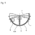
- Fig. 9 shows a second embodiment of the invention in which one of a plurality of Chain links 13 existing chain 12, e.g. a ball chain as a friction adjusting element 3a, 3b is used, the chain links forming a toothing due to their shape in which the gear means 18 engages directly.
- a plurality of Chain links 13 existing chain 12 e.g. a ball chain as a friction adjusting element 3a, 3b is used, the chain links forming a toothing due to their shape in which the gear means 18 engages directly.
- Fig. 10 shows a variant of the second element 2, in its annular / annular Edge / wall 14 recesses 34 are formed, whereby spring means 35 arise, which are provided with the connecting means 4a, 4b, 4c, 4d. In this way, the resilient areas of the friction adjusting elements are dispensed with.
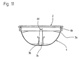
- Fig. 11 shows an external view of the actuator, with the first element 1, the groove-like Has guides 36 in which the friction adjusting elements 3a, 3b extend, the ends of which are connected to the second element 2 via the connection points 4b, 4d.
- 12 shows a first embodiment of a support for the friction adjusting element 3a in the form of snap connections 39.
- the snap connections are in Engagement area of the transmission means 18 in the toothed area of the friction adjusting element arranged.
- 13 is a second embodiment of the support 38a shown, which is designed as a web, the two guides 36 together combines.
- 14 shows a third embodiment of the support 38a, in which a web with one of the guides 36 over a film hinge 40 and with the second guide 36 is connected via a snap connection.
- a fourth embodiment of the 15 shows the support 38b with the second element 2 integrally.
Landscapes
- Engineering & Computer Science (AREA)
- Multimedia (AREA)
- Mechanical Engineering (AREA)
- Mechanical Operated Clutches (AREA)
- Transmission Devices (AREA)
- Pivots And Pivotal Connections (AREA)
Description
- Fig. 1
- eine vereinfachte räumliche Darstellung eines Stellantriebes mit einem ersten und einem zweiten Element,
- Fig. 2
- eine weitere vereinfachte räumliche Darstellung eines Teils des Stellantriebes,
- Fig. 3
- ein Reib-Verstellelement in Form eines Metallbandes mit einer Verzahnung,
- Fig. 4
- eine erste Variante der Verzahnung des Metallbandes,
- Fig. 5
- eine zweite Variante der Verzahnung des Metallbandes
- Fig. 6
- eine räumliche Darstellung des zweiten Elements,
- Fig. 7
- eine zweite räumliche Darstellung des Stellantriebes aus anderer Perspektive,
- Fig. 8
- eine vereinfachte Schnittdarstellung des Stellantriebes,
- Fig. 9
- eine zweite Ausführungsart der Erfindung,
- Fig. 10
- eine räumliche Darstellung einer Variante des zweiten Elements,
- Fig. 11
- eine Außenansicht des Stellantriebs mit Führungen,
- Fig. 12
- eine erste Ausführungsform einer Abstützung,
- Fig. 13
- eine zweite Ausführungsform der Abstützung,
- Fig. 14
- eine dritte Ausführungsform der Abstützung und
- Fig. 15
- eine vierte Ausführungsform einer Abstützung.
- 1
- erstes Element
- 2
- zweites Element
- 3a, 3b
- Reib-Verstellelement
- 4a, 4b, 4c, 4d
- Verbindungsstellen
- 5a, 5b
- Schwenkachsen
- 6
- Schnittpunkt der Schwenkachsen
- 7
- Halterung für Stellglied
- 8
- Stellglied
- 9
- Antrieb
- 10
- Stellantrieb
- 11
- verzahnter Bereich
- 12
- Kette
- 13
- Kettenglieder
- 14
- ringförmiger Rand/ringförmigeWandung
- 15a, 15b, 15c, 15d
- Mitnehmer
- 16
- Wandung
- 17
- Ausnehmungen für Getriebemittel
- 18
- Getriebemittel
- 19
- Ausnehmungen für Positionsermittlungseinrichtung
- 20
- Positionsermittlungseinrichtung
- 21
- Anschlüsse
- 22
- Leitbleche
- 23
- federnder Bereich der Reib-Verstellelemente
- 24
- Schwenklager
- 25
- Kalotte
- 26
- eingeprägte Verzahnung
- 27
- Lochung
- 28
- Verbindungsöffnung
- 29
- Verstrebungen
- 30
- Nut
- 32
- Leiterplatte
- 33
- Schleifer
- 34
- Freisparungen
- 35
- Federmittel
- 36
- Führungen
- 37
- Spiel
- 38a, 38b
- Abstützung
- 39
- Schnappverbindung
- 40
- Filmschamier
Claims (41)
- Stellantrieb (10) für ein Kraftfahrzeug, wobei ein erstes Element (1) an dem Fahrzeug festlegbar ist und ein mit dem ersten Element (1) um zumindest eine Schwenkachse (5a,5b) schwenkbar verbundenes zweites Element (2) eine Halterung (7) für ein Stellglied (8) aufweist und das zweite Element (2) mit zumindest einem, von einem Antrieb (9) zwischen dem ersten und dem zweiten Element (1, 2) betätigbaren, Verstellelement und zumindest einem, an dem ersten Element anliegenden, Reibelement verbunden ist, dadurch gekennzeichnet, daß zumindest ein Reibelement mit einem Verstellelement ein einstückiges Reib-Verstellelement (3a, 3b) bildet, das als Verbindungsmittel zwischen dem ersten und dem zweiten Element (1, 2) dient und das Reib-Verstellelement (3a, 3b) auf Zug belastet ist.
- Stellantrieb nach Anspruch 1, dadurch gekennzeichnet, daß zumindest ein Reib-Verstellelement (3a, 3b) ein Metallband, ein Verbundteil oder ein technisches Kunststoffteil mit mindestens einem verzahnten Bereich (11) ist.
- Stellantrieb nach Anspruch 2, dadurch gekennzeichnet, daß der verzahnte Bereich (11) durch eine eingeprägte Verzahnung (26) gebildet ist.
- Stellantrieb nach Anspruch 2, dadurch gekennzeichnet, daß der verzahnte Bereich (11) durch eine Lochung (27) gebildet ist.
- Stellantrieb nach Anspruch 2, dadurch gekennzeichnet, daß der verzahnte Bereich (11) durch Tiefziehen oder Stanzen und Biegen hergestellt ist.
- Stellantrieb nach Anspruch 1, 2, 3, 4 oder 5, dadurch gekennzeichnet, daß zumindest ein Reib-Verstellelement (3a, 3b) an Verbindungsstellen (4a, 4b, 4c, 4d) mit dem zweiten Element (2) verbunden ist.
- Stellantrieb (10) für ein Kraftfahrzeug, wobei ein erstes Element (1) an dem Fahrzeug festlegbar ist und ein mit dem ersten Element (1) um zumindest eine Schwenkachse (5a,5b) schwenkbar verbundenes zweites Element (2) eine Halterung (7) für ein Stellglied (8) aufweist und das zweite Element (2) mit zumindest einem, von einem Antrieb (9) zwischen dem ersten und dem zweiten Element (1,2) betätigbaren, Verstellelement und zumindest einem, an dem ersten Element anliegenden, Reibelement verbunden ist, dadurch gekennzeichnet, daß eine mehrgliedrige Kette (12) als ein Reib-Verstellmittel (3a; 3b) dient und daß die Kette (12) auf Zug belastet ist.
- Stellantrieb, nach Anspruch 7, dadurch gekennzeichnet, daß der Antrieb in oder zwischen Kettenglieder (13) der Kette (12) eingreift.
- Stellantrieb nach Anspruch 1, 2, 3, 4, 5, 6, 7 oder 8, dadurch gekennzeichnet, daß das zweite Element (2) um zwei rechtwinklig zueinander angeordnete Schwenkachsen (5a, 5b) schwenkbar ist, wobei für jede Schwenkachse ein Reib-Verstellelement (3a, 3b) oder eine Kette (12) vorgesehen ist.
- Stellantrieb nach Anspruch 9, dadurch gekennzeichnet, daßdie beiden Reib-Verstellelemente (3a, 3b) unabhängig voneinander antreibbar sind,jedes Reib-Verstellelement (3a, 3b) an zumindest zwei der Verbindungsstellen (4a, 4b, bzw. 4c, 4d) mit dem zweiten Element (2) verbunden ist,bei Verwendung zweier Verbindungsstellen (4a, 4b, bzw. 4c, 4d) je Reib-Verstellelement (3a, 3b), jeweils eine Verbindungsstelle (4a, 4b) des zweiten Elements (2) mit dem ersten Reib-Verstellelement (3a) auf eine Verbindungsstelle (4c, 4d) des zweiten Elements (2) mit dem zweiten Reib-Verstellelements (3b) folgt, wobei die Verbindungsstellen (4a, 4c, 4b, 4d) in einem gleichmäßigen Winkelabstand von 90° in bezug auf einen Schnittpunkt (6) der beiden Schwenkachsen (5a ,5b) angeordnet sind,jedes Reib-Verstellelement (3a, 3b) das erste Element (1) umfaßt unddie Reib-Verstellelemente (3a, 3b) zumindest teilweise im oder am ersten Element (1) geführt sind.
- Stellantrieb nach Anspruch 10, dadurch gekennzeichnet, daß die beiden Reib-Verstellelemente (3a, 3b) so geformt oder angeordnet sind, daß sie sich nicht gegenseitig behindern können und/oder daß sie aufeinander gleiten.
- Stellantrieb nach Anspruch 10 oder 11, dadurch gekennzeichnet, daß die beiden Reib-Verstellelemente (3a, 3b) sich auf unterschiedlichen Bahnen und zumindest teilweise mit unterschiedlichem Abstand zum Schnittpunkt (6) der Schwenkachsen (5a, 5b) bewegen.
- Stellantrieb nach zumindest einem der vorhergehenden Ansprüche, dadurch gekennzeichnet, daß zumindest auf ein Reib-Verstellelement (3a, 3b) im Stillstand und im Betrieb Zugkräfte wirken.
- Stellantrieb nach zumindest einem der vorhergehenden Ansprüche, dadurch gekennzeichnet, daß das zweite Element (2) im wesentlichen steif ausgebildet ist.
- Stellantrieb nach Anspruch 14, dadurch gekennzeichnet, daß das zweite Element (2) mit einem/einer ringförmigen Rand/Wandung (14) versehen ist.
- Stellantrieb nach Anspruch 15, dadurch gekennzeichnet, daß an dem/der ringförmigen Rand/Wandung (14) die Verbindungsstellen (4a, 4b, 4c, 4d) zu dem zumindest einen Reib-Verstellelement (3a, 3b) angeformt sind.
- Stellantrieb nach Anspruch 14, 15 oder 16, dadurch gekennzeichnet, daß am zweiten Element (2) Federmittel (35) vorgesehen sind, an denen die Verbindungsstellen (4a, 4b, 4c, 4d) zwischen den Reib-Verstellelementen (3a, 3b) und dem zweiten Element (2) angeformt sind.
- Stellantrieb nach Anspruch 17, dadurch gekennzeichnet, daß im zweiten Element (2) schlitzförmige Freisparungen (34) vorgesehen sind, durch welche die Federmittel (35) gebildet werden.
- Stellantrieb nach zumindest einem der vorhergehenden Ansprüche, dadurch gekennzeichnet, daß zumindest ein Reib-Verstellelement (3a, 3b) gelenkig mit dem zweiten Element (2) verbunden ist.
- Stellantrieb nach zumindest einem der vorhergehenden Ansprüche, dadurch gekennzeichnet, daß zwischen dem ersten (1) und dem zweiten Element (2) ein Schwenklager (24) vorgesehen ist, das nur von einem oder von zwei Reib-Verstellelementen (3a, 3b) zusammengehalten wird.
- Stellantrieb nach zumindest einem der vorhergehenden Ansprüche, dadurch gekennzeichnet, daß in einer Wandung (16) des ersten Elements (1) Ausnehmungen (17) vorhanden sind, durch welche Getriebemittel (18) des Antriebes (9) mit den Reib-Verstellelementen (3a, 3b) in Eingriff kommen können.
- Steilantrieb nach zumindest einem der vorhergehenden Ansprüche, dadurch gekennzeichnet, daß die Reib-Verstellelemente (3a, 3b) rechtwinklig zur Verstellrichtung flexibel oder starr ausgebildet sind.
- Stellantrieb nach zumindest einem der vorhergehenden Ansprüche, dadurch gekennzeichnet, daß bei flexibler Ausbildung die Reib-Verstellelemente (3a, 3b) an deren Verbindungsstellen (4a, 4b, 4c, 4d) mit dem zweiten Element (2) seitlich fixiert sind.
- Stellantrieb nach zumindest einem der vorhergehenden Ansprüche, dadurch gekennzeichnet, daß die Winkel der Reib-Verstellelemente (3a, 3b) zueinander in den Extremstellungen des zweiten Elements (2) geringfügig von 90° abweichen können.
- Stellantrieb nach zumindest einem der vorhergehenden Ansprüche, dadurch gekennzeichnet, daß bei starrer Ausbildung zumindest ein Reib-Verstellelement (3a, 3b) an zumindest einer Verbindungsstelle (4a, 4b, 4c, 4d) mit dem zweiten Element (2) seitliche Ausweichmöglichkeiten besitzt.
- Stellantrieb nach zumindest einem der vorhergehenden Ansprüche, dadurch gekennzeichnet, daß zumindest ein Reib-Verstellelement (3a, 3b) am ersten Element (1) in Führungen (36) seitlich geführt ist.
- Stellantrieb nach Anspruch 26, dadurch gekennzeichnet, daß das Reib-Verstellelement (3a, 3b) in den Führungen (36) beidseitig geführt ist.
- Stellantrieb nach Anspruch 26 oder 27, dadurch gekennzeichnet, daß zumindest ein Reib-Verstellelement (3a, 3b) mit keinem oder nur sehr geringem Spiel in den Führungen (36) längsbeweglich gelagert ist.
- Stellantrieb nach Anspruch 28, dadurch gekennzeichnet, daß zumindest ein Reib-Verstellelement (3a, 3b) in Verbindung mit der Führung (36) als Verdrehsicherungselement dient.
- Stellantrieb nach Anspruch 26, 27, 28 oder 29, dadurch gekennzeichnet, daß zumindest ein Reib-Verstellelement (3a, 3b) mit deutlichem Spiel (37) in den Führungen (36) längsbeweglich und geringfügig seitlich beweglich gelagert ist.
- Stellantrieb nach zumindest einem der vorhergehenden Ansprüche, dadurch gekennzeichnet, daß der verzahnte Bereich (11) zumindest eines Reib-Verstellelements (3a, 3b) dem ersten Element (1) zugewandt ist oder um ca. 90° dazu angeordnet/ausgerichtet ist.
- Stellantrieb nach Anspruch 31, dadurch gekennzeichnet, daß zumindest ein Reib-Verstellelement (3a, 3b) zumindest im Eingriffsbereich mit dem Getriebemittel (18) durch ein Abstützmittel (38a, 38b) abgestützt ist.
- Stellantrieb nach Anspruch 32, dadurch gekennzeichnet, daß das Reib-Verstellelement (3a, 3b) durch eine Schnappverbindung (39) in der Führung gehalten wird.
- Steilantrieb nach Anspruch 32, dadurch gekennzeichnet, daß das Abstützmittel (38a, 38b) einstückig mit dem ersten Element (1) oder einstückig mit dem zweiten Element (2) ist.
- Stellantrieb nach zumindest einem der vorhergehenden Ansprüche, dadurch gekennzeichnet, daß zwischen dem ersten Element (1) und dem zweiten Element (2) ein Federelement angeordnet ist.
- Stellantrieb nach Anspruch 35, dadurch gekennzeichnet, daß das Federelement einstückig mit dem ersten Element (1) oder dem zweiten Element(2) ist, oder daß ein zusätzliches Federelement vorgesehen ist.
- Stellantrieb nach Anspruch 35 oder 36, dadurch gekennzeichnet, daß das Federelement versucht das zweite Element (2) vom ersten Element (1) weg zu bewegen und daß zumindest ein Reib-Verstellelement (3a, 3b) das zweite Element (2) gegen die Federwirkung des Federelements am ersten Element (1) hält.
- Stellantrieb nach zumindest einem der vorhergehenden Ansprüche, dadurch gekennzeichnet, daß das erste Element (1) Ausnehmungen (19) in der Wandung (16) aufweist, durch welche zumindest eine Positionsermittlungseinrichtung (20) mit den Reib-Verstellelementen (3a, 3b) gekoppelt werden kann.
- Stellantrieb nach zumindest einem der vorhergehenden Ansprüche, dadurch gekennzeichnet, daß ein Teil der Positionsermittlungseinrichtung (20) innerhalb des ersten Elements (1) angeordnet ist und ein zweiter Teil fest mit einem Reib-Verstellelement (3a, 3b) verbunden ist, wobei eine Verbindung zwischen den beiden Teilen durch die Wandung (16) des ersten Elementes hergestellt wird.
- Stellantrieb nach zumindest einem der vorhergehenden Ansprüche, dadurch gekennzeichnet, daß die Positionsermittlungseinrichtung (20) nachträglich von außen auf das erste Element aufgesetzt und mechanisch sowie elektrisch mit diesem verbunden werden kann.
- Stellantrieb nach zumindest einem der vorhergehenden Ansprüche, dadurch gekennzeichnet, daß das Stellglied (8) ein Kfz-Rückblickspiegel ist.
Applications Claiming Priority (2)
| Application Number | Priority Date | Filing Date | Title |
|---|---|---|---|
| DE19919529 | 1999-04-29 | ||
| DE19919529A DE19919529B4 (de) | 1999-01-25 | 1999-04-29 | Stellantrieb für ein Kraftfahrzeug |
Publications (2)
| Publication Number | Publication Date |
|---|---|
| EP1063125A1 EP1063125A1 (de) | 2000-12-27 |
| EP1063125B1 true EP1063125B1 (de) | 2002-07-24 |
Family
ID=7906296
Family Applications (1)
| Application Number | Title | Priority Date | Filing Date |
|---|---|---|---|
| EP00108886A Expired - Lifetime EP1063125B1 (de) | 1999-04-29 | 2000-04-27 | Stellantrieb für ein Kraftfahrzeug |
Country Status (2)
| Country | Link |
|---|---|
| US (1) | US6341536B1 (de) |
| EP (1) | EP1063125B1 (de) |
Families Citing this family (11)
| Publication number | Priority date | Publication date | Assignee | Title |
|---|---|---|---|---|
| DE29923786U1 (de) * | 1999-07-21 | 2001-04-19 | Magna Auteca Zweigniederlassung Der Magna Holding Ag, Weiz | Antriebsvorrichtung für einen verstellbaren Rückblickspiegel mit einem selbstkalibrierenden Potentiometer |
| NL1015428C2 (nl) * | 2000-06-14 | 2001-12-17 | Iku Holding Montfoort Bv | Bewegingsmechanisme. |
| DE10058730A1 (de) * | 2000-11-25 | 2003-01-02 | Buhler Motor Gmbh | Verstellvorrichtung für Kraftfahrzeug-Außenspiegel |
| DE50103429D1 (de) * | 2001-03-12 | 2004-09-30 | Oechsler Ag | Motorische verschwenkeinrichtung für eine träger-platte insbesondere zur aufnahme eines kraftfahrzeugspiegels |
| DE10152813B4 (de) * | 2001-10-25 | 2005-12-08 | Em Kunststofftechnik Gmbh | Antriebsanordnung zum gesteuerten mehrachsigen Verstellen, insbesondere eines Kraftfahrzeug-Rückblickspiegels |
| US20040207940A1 (en) * | 2003-04-02 | 2004-10-21 | Carter John W | Interior rearview mirror with magnesium components |
| EP2415640B1 (de) | 2010-08-03 | 2013-02-13 | SMR Patents S.à.r.l. | Außenrückspiegel und Verfahren zu dessen Montage |
| KR101652889B1 (ko) * | 2015-03-13 | 2016-09-01 | 주식회사 호영자동차부품 | 자동차용 아웃사이드미러 조정 장치 |
| DE202019100579U1 (de) * | 2019-01-31 | 2019-02-25 | Mci (Mirror Controls International) Netherlands B.V. | Sichteinstellmechanismus |
| DE102019108303B4 (de) * | 2019-03-29 | 2020-12-10 | Mci (Mirror Controls International) Netherlands B.V. | Sichteinstellmechanismus und Stellmittel für einen solchen |
| DE102019215213B3 (de) * | 2019-10-02 | 2020-10-01 | Festo Se & Co. Kg | Gelenkvorrichtung |
Family Cites Families (10)
| Publication number | Priority date | Publication date | Assignee | Title |
|---|---|---|---|---|
| DE2453498C3 (de) * | 1974-11-12 | 1978-07-13 | Ymos-Metallwerke Wolf & Becker Gmbh & Co, 6055 Hausen | Ferneinstellbarer Außenspiegel für Kraftfahrzeuge |
| NL183086C (nl) * | 1977-01-10 | 1988-07-18 | Koot Ind Bv | Inrichting voor het verstellen van een buitenspiegel, alsmede een veiligheidshuis geschikt voor het opnemen van de inrichting. |
| US4101206A (en) | 1976-04-09 | 1978-07-18 | Industrie Koot B.V. | Adjustable motor car mirror with compact electrically driven adjusting means |
| NL189807C (nl) | 1979-07-26 | 1993-08-02 | Iku Holding Montfoort Bv | Spiegelverstelinrichting voor een buitenspiegel van een voertuig. |
| US4628760A (en) * | 1983-01-17 | 1986-12-16 | Harman Automotive, Inc. | Remote control rearview mirror and pivot |
| JPS6231540A (ja) * | 1985-08-05 | 1987-02-10 | Honda Motor Co Ltd | 自動車用ミラ−の駆動方法 |
| US5467230A (en) * | 1993-08-16 | 1995-11-14 | Lowell Engineering Corp. | Dual pivoted member mount for mirror |
| AT405501B (de) | 1997-01-17 | 1999-09-27 | Magna Reflex Holding Gmbh | Verstellbarer rückspiegel, insbesondere aussenspiegel, für ein kraftfahrzeug |
| BR9702665A (pt) * | 1997-07-28 | 1999-10-05 | Metagal Ind Stria E Comercio L | Articulação multiuso para espelhos retrovisores externos |
| NL1007139C2 (nl) * | 1997-09-26 | 1999-03-29 | Iku Holding Montfoort Bv | Actuator. |
-
2000
- 2000-04-26 US US09/559,398 patent/US6341536B1/en not_active Expired - Fee Related
- 2000-04-27 EP EP00108886A patent/EP1063125B1/de not_active Expired - Lifetime
Also Published As
| Publication number | Publication date |
|---|---|
| US6341536B1 (en) | 2002-01-29 |
| EP1063125A1 (de) | 2000-12-27 |
Similar Documents
| Publication | Publication Date | Title |
|---|---|---|
| DE3026561C2 (de) | ||
| DE69030388T2 (de) | Rückblickspiegel für kraftfahrzeug | |
| DE3882896T2 (de) | Elektrisch schwenkbarer Türspiegel. | |
| DE69427760T2 (de) | Verbessertes doppelgelenkmontageelement für einen spiegel | |
| DE19527912C2 (de) | Beidseitig wirkender, manueller Antrieb zur Erzeugung einer Drehbewegung, insbesondere für Kraftfahrzeugsitze | |
| DE3881495T2 (de) | Antriebseinheit fuer elektrisch fernbedienbaren spiegel. | |
| DE19919529B4 (de) | Stellantrieb für ein Kraftfahrzeug | |
| EP1063125A1 (de) | Stellantrieb für ein Kraftfahrzeug | |
| EP2934937B1 (de) | Pedaleinheit für ein kfz | |
| EP3789239A1 (de) | Fahrzeugsitz mit drehverstelleinrichtung | |
| DE69208332T2 (de) | Einstellungseinrichtung für Scheinwerfer | |
| DE69924205T2 (de) | Ferngesteurter Fahrzeugspiegel | |
| DE10162519B4 (de) | Manuell anklappbarer Türspiegel | |
| DE19912755A1 (de) | Antriebseinrichtung zum Verstellen eines in einem Spiegelgehäuse eines Kraftfahrzeug-Rückblickspiegels schwenkbar gelagerten Spiegelglasträgers | |
| DE69806775T2 (de) | Betätigungseinrichtung | |
| DE102004039057B3 (de) | Untersetzungsgetriebe und dieses verwendende Antriebseinheit | |
| DE10042678C2 (de) | Vorrichtung zum Bewegen eines Körpers, insbesondere eines Fahrzeugteils und vorzugsweise eines Fahrzeugspiegels | |
| DE69511645T2 (de) | Dämpfendes schwungrad, insbesondere für kraftfahrzeuge | |
| DE10219477C1 (de) | Mehrwegeschaltmittel | |
| DE4420790B4 (de) | Betätigungsvorrichtung für eine Drosselklappe | |
| DE2644074A1 (de) | Vorrichtung zum verschwenken eines spiegels, insbesondere kraftfahrzeug- rueckspiegels | |
| EP2277210B1 (de) | Rotationsantrieb | |
| DE4323938A1 (de) | Heck-Beobachtungsspiegelvorrichtung für ein Fahrzeug | |
| DE3416656C2 (de) | ||
| DE69613758T2 (de) | Rollende Arretiervorrichtung |
Legal Events
| Date | Code | Title | Description |
|---|---|---|---|
| PUAI | Public reference made under article 153(3) epc to a published international application that has entered the european phase |
Free format text: ORIGINAL CODE: 0009012 |
|
| AK | Designated contracting states |
Kind code of ref document: A1 Designated state(s): FR GB |
|
| AX | Request for extension of the european patent |
Free format text: AL;LT;LV;MK;RO;SI |
|
| 17P | Request for examination filed |
Effective date: 20001212 |
|
| AKX | Designation fees paid | ||
| RBV | Designated contracting states (corrected) |
Designated state(s): FR GB |
|
| GRAG | Despatch of communication of intention to grant |
Free format text: ORIGINAL CODE: EPIDOS AGRA |
|
| GRAG | Despatch of communication of intention to grant |
Free format text: ORIGINAL CODE: EPIDOS AGRA |
|
| GRAH | Despatch of communication of intention to grant a patent |
Free format text: ORIGINAL CODE: EPIDOS IGRA |
|
| 17Q | First examination report despatched |
Effective date: 20011227 |
|
| GRAH | Despatch of communication of intention to grant a patent |
Free format text: ORIGINAL CODE: EPIDOS IGRA |
|
| REG | Reference to a national code |
Ref country code: DE Ref legal event code: 8566 |
|
| GRAA | (expected) grant |
Free format text: ORIGINAL CODE: 0009210 |
|
| AK | Designated contracting states |
Kind code of ref document: B1 Designated state(s): FR GB |
|
| REG | Reference to a national code |
Ref country code: GB Ref legal event code: FG4D Free format text: NOT ENGLISH |
|
| GBT | Gb: translation of ep patent filed (gb section 77(6)(a)/1977) |
Effective date: 20020813 |
|
| ET | Fr: translation filed | ||
| PLBE | No opposition filed within time limit |
Free format text: ORIGINAL CODE: 0009261 |
|
| STAA | Information on the status of an ep patent application or granted ep patent |
Free format text: STATUS: NO OPPOSITION FILED WITHIN TIME LIMIT |
|
| 26N | No opposition filed |
Effective date: 20030425 |
|
| PGFP | Annual fee paid to national office [announced via postgrant information from national office to epo] |
Ref country code: GB Payment date: 20080430 Year of fee payment: 9 |
|
| PGFP | Annual fee paid to national office [announced via postgrant information from national office to epo] |
Ref country code: FR Payment date: 20090212 Year of fee payment: 10 |
|
| GBPC | Gb: european patent ceased through non-payment of renewal fee |
Effective date: 20090427 |
|
| PG25 | Lapsed in a contracting state [announced via postgrant information from national office to epo] |
Ref country code: GB Free format text: LAPSE BECAUSE OF NON-PAYMENT OF DUE FEES Effective date: 20090427 |
|
| REG | Reference to a national code |
Ref country code: FR Ref legal event code: ST Effective date: 20101230 |
|
| PG25 | Lapsed in a contracting state [announced via postgrant information from national office to epo] |
Ref country code: FR Free format text: LAPSE BECAUSE OF NON-PAYMENT OF DUE FEES Effective date: 20100430 |