EP1062896B1 - Présentoir - Google Patents
Présentoir Download PDFInfo
- Publication number
- EP1062896B1 EP1062896B1 EP00305344A EP00305344A EP1062896B1 EP 1062896 B1 EP1062896 B1 EP 1062896B1 EP 00305344 A EP00305344 A EP 00305344A EP 00305344 A EP00305344 A EP 00305344A EP 1062896 B1 EP1062896 B1 EP 1062896B1
- Authority
- EP
- European Patent Office
- Prior art keywords
- module
- display apparatus
- slot
- wall
- base portion
- Prior art date
- Legal status (The legal status is an assumption and is not a legal conclusion. Google has not performed a legal analysis and makes no representation as to the accuracy of the status listed.)
- Expired - Lifetime
Links
Images


Classifications
-
- A—HUMAN NECESSITIES
- A47—FURNITURE; DOMESTIC ARTICLES OR APPLIANCES; COFFEE MILLS; SPICE MILLS; SUCTION CLEANERS IN GENERAL
- A47F—SPECIAL FURNITURE, FITTINGS, OR ACCESSORIES FOR SHOPS, STOREHOUSES, BARS, RESTAURANTS OR THE LIKE; PAYING COUNTERS
- A47F7/00—Show stands, hangers, or shelves, adapted for particular articles or materials
- A47F7/14—Show stands, hangers, or shelves, adapted for particular articles or materials for pictures, e.g. in combination with books or seed-bags ; for cards, magazines, newspapers, books or booklike articles, e.g. audio/video cassettes
- A47F7/144—Show stands, hangers, or shelves, adapted for particular articles or materials for pictures, e.g. in combination with books or seed-bags ; for cards, magazines, newspapers, books or booklike articles, e.g. audio/video cassettes the show stands or the like being provided with trays, shelves or adjustable partitioning means therefor
- A47F7/145—Terraced shelves
Definitions
- This invention relates to a display apparatus, in particular but not exclusively for use in retail environments such as shops.
- the display apparatus of the invention may also be used e.g. in banks, hospitals, offices and indeed virtually anywhere that it is required to provide an attractive display of articles.
- EP-A-0295869 discloses a display apparatus intended primarily for the displaying of laminar articles such as cards, leaflets, sheets, brochures and magazines.
- EP-A-0295869 discloses a plurality of elongate channels suspended one below another, each channel being of generally J-shaped cross section for supporting articles in the trough thereby formed.
- Each J-shaped trough has a longer arm and a shorter arm.
- the apparatus includes a support for supporting each lower J-shaped channel on the next higher J-shaped channel.
- the support includes a hook, which is provided on the longer arm of each lower J-shaped channel and which hooks over the shorter arm of the next higher J-shaped channel whereby each lower J-shaped channel is suspended from the shorter, forward arm of the next higher J-shaped channel so as to provide a suspended tiered display.
- EP-A-0295869 may be readily dismantled for transportation, storage and replacement.
- each lower J-shaped channel is suspended from the shorter arm (i.e. the front arm) of the upwardly adjacent J-shaped channel. This means that, in order to provide a visually attractive display, all the J-shaped channels must have longer and shorter arms of the same respective lengths.
- the formation of the upper end of the longer arm of each J-shaped channel as a hook, that hooks over the shorter arm of the next upwardly adjacent J-shaped channel means that some of the space, between the shorter and longer arms defining the trough for displaying articles, is occupied by the material of the hook. This limits the available distance between the front and rear arms, and hence the quantity of articles that can be displayed in the apparatus of EP-A-0295869. This is important when the articles displayed are, e.g. greetings cards.
- EP-A-0 225 568 discloses a modular display apparatus in which an upper module has two upstanding walls interconnected at a base portion of the upper module and defining a first receptacle, that is open at its upper end, for receiving articles for display; and a first, lower module that is supportable beneath the upper module, the first, lower module having two upstanding walls defining a further receptacle, that is open at its upper end, for receiving articles for display; the base portion of the upper module and an upper portion of the first, lower module including mutually engageable hanger parts releasably hanging the first lower module beneath and partly forwardly of the upper module so as to permit access of articles via each of the receptacles, the hanger parts, when engaged, defining a joint that precludes angular rotation between the upper and lower adjacent modules both in a plane normal to an axis of the modules and in terms of relative rotation between the modules.
- the locating of mutually engagable hanger parts respectively at the base portion of an upper module and at an upper part of a lower module means that it is not necessary to provide a hook for hooking the lower module onto the front wall of the upper module.
- at least the front wall of the apparatus may be decorated e.g by means of the addition embellishments, or by virtue of having a non-rectilinear upper edge.
- the apparatus of the invention remains readily dismantleable and reassemblable.
- the absence of any attachment involving the front wall of the receptacle means that the front wall at least may be made to any height to suit the application under consideration. This in turn provides the option of having differently sized modules within a single display, without any detrimental effect on the overall visual attractiveness of the display.
- a lower part of the rear wall of each channel is provided by the rear wall of the lower module, and an upper part of the rear wall of each receptacle is provided by the front wall of an upper module.
- Claims 2 and 3 define features that permit the connecting together, in a tiered display, of more than two of the modules of the apparatus.
- Claim 4 defines the boundary between the rear wall of a lower module and the front wall of the next upwardly adjacent module.
- the use of a substantially contiguous boundary as defined in Claim 4 advantageously provides a neat, attractive appearance to the display apparatus.
- the said substantially contiguous boundary is non-rectilinear. This feature may be used to produce attractive visual effects, e.g. when the rear wall of the lower module is a different colour than the front wall of the upper adjacent module.
- each lower module is generally parallel to the front wall of the upwardly adjoining module when the modules are connected together. This allows the apparatus conveniently to display flat laminar items such as greetings cards.
- the rear wall of a lower module is not parallel to the front wall of the next upwardly adjoining module. This may be of benefit when displaying curved items.
- each module is of generally equal heights. This allows the manufacture of a standard module size, that may be used to build up a tiered display of virtually any preferred depth.
- the apparatus may include a module whose upstanding walls are of unequal heights.
- a display apparatus may if desired include both modules having walls of equal heights; and modules having walls of unequal heights, as required.
- At least the front wall of a said module may include ornamental features.
- An example of such an ornamental feature is that of a non-rectilinear free edge to the front wall of a module.
- the said upper edge may include cut-outs or recesses to define a preferred image or pattern.
- the said front wall to include eg embossments and/or recesses, to enhance the appearance of the display or for other purposes as disclosed hereinbelow.
- Claim 11 defines an advantageously simple means for connecting the upper portion of a lower module to the base portion of an upper module of the apparatus. It is inherent in the arrangement of the invention that the front wall of a said module need not be parallel to the rear wall of the module below, since the angle of the front wall does not determine the angle at which the rear wall is supported.
- Claims 12 and 13 define further means for connecting the upper portion of a lower module to the base portion of an upper module.
- Claim 14 defines a particularly preferred embodiment of the invention, in which a base wall spaces the front and rear walls of the module. This allows the said walls to lie parallel to one another. Such an arrangement is highly suitable for displaying greetings cards and other laminar items.
- Claim 15 defines a further feature that advantageously assists in the display of thin, laminar items such as greetings cards.
- Claim 16 defines an elongate channel that permits the slidable retention in at least one of the modules of the apparatus of a movable divider for subdividing the interior of a said receptacle.
- the channel for receiving the divider extends longitudinally from one end of the apparatus to the other parallel to the base portion of its associated module, although other shapes and positions for the channel are possible.
- the arrangement of the invention advantageously permits the presence of the channel, for receiving the divider, as a depression in the surface of a wall that results in a protuberance on the other side of the wall. This is because, in contrast with EP-A-0295869, there are no overlapping walls in the apparatus of the invention.
- Claims 17 and 18 define covenient means by which the apparatus may be assembled and suspended.
- Claims 19 and 20 define an arrangement by means of which the orientation of the apparatus, relative to a fixed surface such as a wall, may readily be adjusted. This improves the versatility of the apparatus.
- Claims 21 to 23 define a further arrangement which the orientation of the apparatus, relative to a fixed surface such as a wall, may readily be adjusted.
- Claim 24 defines another form of divider. Use of this divider is facilitated by the fact that the upper edge of each upstanding wall is free. Therefore the U-shaped portion of the divider can be a comparatively slim component. Assuming that the two upstanding walls are each of the same thickness, the U-shaped portion may be slidingly fitted over either of them. The divider may readily be removed from the apparatus, rotated through 180° and replaced. Thus the divider may project either forwardly or rearwardly relative to one of the upstanding walls, as required.
- Claim 25 defines another form of divider.
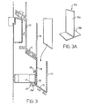
- the apparatus 10 is a modular display apparatus comprising an upper module 11 and a lower module 16.
- Module 11 includes a pair, 12, 13 of upstanding side walls.
- Side walls 12, 13 are in the embodiment of Figure 1 generally parallel to one another and spaced from one another in a horizontal direction.
- Walls 12, 13 are in the Figure 1 embodiment of generally the same length as each other, although this need not necessarily be so.
- Walls 12, 13 are interconnected by a bottom wall 14 at the base portion of upper module 11.
- the bottom wall 14 is inclined at an obtuse angle relative to rear wall 13, and at an acute angle to front wall 12 so that the walls 12, 13, 14 in the embodiment of Figure 1 generally define three sides of a parallelogram or trapezium shape when viewed in cross section.
- the walls 12, 13, 14 define a first receptacle, open at its upper end in use of the display apparatus.
- the receptacle is dimensioned to be suitable for receiving articles for display (not shown in the drawings).
- Figure 1 shows a first, lower module 16, having substantially identical front and rear walls 17, 18 that are substantially parallel to one another and interconnected at the base portion of lower module 16 by bottom wall 19.
- the walls 17, 18, 19 define a further receptacle, similar to the receptacle of upper module 11, that is open at its upper end for receiving articles for display (not shown in the drawings).
- Lower module 16 is suspended beneath upper module 11 by means of mutually engageable connector parts formed on or secured to the base portion of the upper module 11 and an upper portion of the first lower module 16.
- the connector parts secured on the base portion of upper module 11 include a pair of flanged members 20, 22.
- Each flanged member 20, 22 includes a generally downwardly extending wall 20a, 22a protruding perpendicular to the exterior of bottom wall 14; and a respective flange 20b, 22b extending generally perpendicular to each downwardly depending wall 20a, 22a.
- the flanges 20b, 22b are generally parallel to one another and when viewed in cross-section extend in mutually opposite directions, so that the flange members 20, 22 together define a T-shaped member for engagement with connector parts located at the top of the first lower module 16.
- the flanges 20b, 22b extend for part or all of the length of the underside of bottom wall 14.
- the connector parts at the top of first lower module 16 include a slot 23 of generally complementary shape to the T-shape defined by the flange members 20, 22.
- the slot 23 is defined by a elongate plate 24 extending from the upper end of rear wall 18, at an angle substantially parallel to that of bottom wall 14 of upper module 11, when walls 12 and 18 lie parallel to one another.
- flanges 25, 26 Extending parallel to plate 24, and spaced a short vertical distance above it, are two mutually parallel flanges 25, 26.
- the flanges 25, 26 are spaced from one another by a central aperture extending along their respective lengths for receiving the flange members 20, 22.
- Flange 25 that is remote from wall 18, is connected to plate 23 by means of an upstand 28.
- Flange 26 is connected to a short extension 29 of the top of wall 18.
- Bottom wall 19 of first lower module 16 includes flange members 120 122 identical to flange members 20, 22 of upper module 11.
- a further article typically but not necessarily a further module such as lower module 16 may thus be suspended from the base portion of first lower module 16.
- the further article is a further module similar or identical to first lower module 16, it is readily possible to build up a tiered display including a descending cascade of the receptacles.
- the tiered display may in theory have any number of modules, to suit the precise requirements of the installation.
- each front wall, 11, 17, etc of each module is not used for suspending a lower module beneath an upper module. Consequently the outer face and upper edge of each such front wall are available for display and/or support purposes.
- each upper edge can include e.g an undulatory profile or another shape, thereby enhancing the appearance of the display when empty.
- each front wall may include embossments, recesses, apertures, printed decorations, surface textures and the like that either are visually appealing or are of assistance in supporting articles to be displayed in the apparatus.
- the arrangement of suspending an upper portion of the lower module from the base portion of an upper module may result in a neat, comparatively narrow line joint 30 between the two modules.
- this line joint may also may be arranged to be non-rectilinear, or may be a straight line that is inclined for aesthetic purposes.
- the angle at which the plate 24 and flanges 25, 26 protrude relative to the wall 18 determines whether wall 18 lies parallel to wall 12, or at an angle thereto.
- the walls 12 and 18 may readily be manufactured in different colours, in order to produce a chosen aesthetic effect when the display apparatus is empty.
- front and rear walls of each module are of substantially the same height.
- one of the walls preferably but not necessarily the front wall 12 or 17
- the overall depth of a tiered display of the modules is determined by the lengths of the rear walls 13, 18, if the rear walls 13, 18 are all of the same length the differently dimensioned front walls 12, 17 may be employed without having an adverse effect on the overall dimensions of the tiered display.
- Each of the modules 11, 16 includes a series of ribs 31 formed parallel to one another and extending transversely of each rear wall 13, 18 and bottom wall 14, 19.
- the ribs assist in supporting laminar articles such as greetings cards in preferred locations in the apparatus.
- Each of the modules 11, 16 shown in Figure 1 includes, adjacent the upper end of its respective rear wall 13, 18, a protuberance 32 formed on the outer surface of the respective rear wall.
- Each protuberance extends longitudinally along the length of the rear wall on which it is formed.
- the inner surface of the said wall includes an L-shaped slot 32a extending rearwardly into the protuberance.
- the L-shaped slot extends along the length of the protuberance 32.
- the slot 32a is intended to receive a moveable divider 34 for the receptacle of the module 11, 16.
- the divider 34 includes a forwardly extending, laminar member 35 extending perpendicular to a support member 36 whose cross section is cranked to be of complementary shape to the L-shaped slot. It will thus be seen that the support member 36 may readily be inserted into the L-shaped slot at the top of each module, in order to support the laminar member 35 in a cantilever fashion.
- the divider 34 may be slid along the slot 32a to any chosen position in the associated module, in order to subdivide the interior of the module.
- the elongate plate 24 of at least the upper module 11 has formed therein a circular, though-going aperture 37.
- the diameter of aperture 37 is less than the distance separating the edges of the flanges 25, 26 above the aperture 37.
- the aperture 37 permits the upper module 11 to be pivotally suspended by means of a pin 38 that is of smaller diameter than the aperture 37.
- Pin 38 may be secured to a bracket or boss 40 that includes one or more projections 41 for rigid securing e.g to a slot wall.
- Pin 38 may be secured to any other fast item to provide a suitable hanging point for the tiered display.
- pin 38 protrudes though aperture 37 and upwardly beyond the flanges 25, 26 via the space there between.
- At least a lower module such as module 16 includes formed on the outer surface of its rear wall 18 a slot 42 for a strut 43.
- Slot 42 includes an upper formation 44 and a lower formation 46.
- Upper formation 44 includes an upper wall 47 protruding perpendicular to the outer surface of rear wall 18, preferably but not necessarily along the length thereof.
- a further wall 48 depends downwardly from upper wall 47 at an acute angle to wall 18, to define an inverted V-shaped channel.
- Lower formation 46 is substantially sinusoidal in cross section as shown, and extends preferably but not necessarily along the length of the outer surface of wall 18.
- Lower formation 46 is spaced downwardly from upper formation 44.
- Lower formation 46 defines two generally parallel sided slots 49, 50 that are open at their upper ends and disposed opposite the inverted V-shaped slot defined by upper formation 44.
- Parallel sided slot 50 extends generally parallel to wall 18; whereas parallel sided slot 49 extends generally parallel to further wall 48 of upper formation 44.
- Strut 43 includes a tubular member 52 that in the as-manufactured state is open at either end.
- tubular member 52 remote from the display apparatus is closed by means of bung 53 inserted in the open end.
- Bung 53 has a domed outer surface to act as a bumper for bracing against a solid surface such the slot wall that supports the bracket 40.
- tubular member 52 adjacent display apparatus 10 receives inserted therein a further bung 54 that terminates at its free end in a flange 55 that protrudes outwardly beyond the extremity of tubular member 52.
- flange 55 in the vertical direction visible in Figure 1 corresponds to the distance between juxtaposed pairs of slots defined by the upper and lower formations 44, 46. Therefore if flange 55 is slid into one of the slots 49, 50 and simultaneously into the V-shaped slot defined by upper formation 44, the strut 43 is retained slideably captive relative to the apparatus 10.
- strut 43 spaces the lower portion of the display apparatus 10 from e.g the slot wall, and simultaneously braces the lower part of the display apparatus 10.
- the flange 55 is received in the V-shaped slot and in slot 49, to support the recesses defined by the modules at an angle relative to the slot wall. This allows for slight fanning of laminar articles displayed in the apparatus. It also ensures that any stack of flexible articles received in any of the modules is tilted backwards, thereby preventing the articles from flopping over forwardly.
- the modules 11, 16 extend substantially vertically (i.e parallel to the slot wall, etc).
- the lower formation 46 includes two parallel sided slots 49, 50 that extend generally parallel to wall 48 and wall 18 respectively, and it also includes a further parallel sided slot 49a, provided between these two slots 49, 50. This further slot 49a extends generally at an angle between the angle of the other two slots 49, 50.
- This further slot 49a allows mounting of the display in a further configuration in which the modules do not extend substantially vertically, but extend at an angle that is mid-way between the vertical position and the position defined by slot 49, relative to the slot wall.
- the aperture 37 and the formations 44, 46 are respectively described with regard to the upper 11 and lower 16 modules, in preferred embodiments all the modules of a plurality making up a tiered display would include both the aperture 37 and the formations 44, 46, in order to standardise the manufacturing process and assist in assembly of a display.
- a bottom portion of the boss or bracket 40 protrudes between the formations 44 and 46 of the upper module 11.
- the formations and the bracket 40 are shaped so as to avoid fouling of the lower module 46 on the bracket 40.
- Figure 2 shows an alternative form of divider 34a.
- Figure 2a shows the divider 34a in perspective.
- Divider 34a includes a laminar member 35a similar to the laminar member 35 of divider 34 shown in Figure 1. However, instead of having a member of cranked profile extending perpendicular to laminar member 35, divider 34a instead has an n section member 36a extending perpendicular to laminar member 35a.
- the spacing between the downwardly depending limbs of the n-shaped member 36a is slightly greater than the thickness of the walls 12, 17 at the front of each respective module. It will thus be apparent that the n-shaped member 36a may simply be fitted over the upper, free end of such a wall 12, 16 in order to provide a slidable support for the divider.
- each n-shaped member 36a is short compared with the overall length of the display apparatus in the transverse direction, the divider 34a may be employed even when the upper, free edge of a wall such as wall 12 or wall 17 is non-rectilinear.
- Divider 34a has the advantage that it may be positioned with the laminar member 35a projecting either forwardly or rearwardly relative to the wall to which it is slideably secured. Thus the divider may serve to divide either the recess forward of it, or the recess to the rear of it, at the option of the user of the display apparatus.
- Figure 2 omits the channel 32 visible in Figure 1.
- Figure 1 may readily be positioned in a vertical orientation identical to that of Figure 2, notwithstanding the use of the alternative divider 35a.
- Figure 3 shows another form of divider 34b.
- Figures 3a and 3b show the divider 34b in perspective.
- Divider 34b includes a laminar upstand 35b that is connected to a laminar foot member 36b to form a generally inverted T-shaped configuration.
- the bottom edge of laminar upstand 35b is angled relative to the base of the recess defined by the module in which the divider 34b is to be positioned.
- the angle of the bottom edge of the laminar upstand 35b ensures that when divider 34b is positioned to divide the recess, the laminar foot member 36b attached at right angles to this bottom edge, lies flat against the bottom wall 14 or 19 of the module.
- the laminar upstand 35b then extends upwards between and generally parallel to, the side walls 12 and 13, or 17 and 18 of the module in which it is positioned as can be seen in Figure 3b.
- the connector part secured on the base portion of the upper module 11 includes a single flanged member 220.
- This flanged member includes a generally downwardly extending wall 220a protruding parallel to the front wall 12, from the front edge of the bottom wall 14; and a respective flange 220b extending generally parallel to the base wall 14.
- the flange 220b extends from the front to the back edge of bottom wall 14.
- the flange member 220 hence defines a member for engagement with a connector part located at the top of the first lower module 16.
- the connector part at the top of the first lower module 16 includes a single slot member 223.
- This slot member 223 is defined by an elongate plate 224 extending from the upper end of rear wall 18, at an angle substantially parallel to that of the bottom wall 14 of the upper module 11, when walls 12 and 18 lie parallel to each other.
- Flange 225 Extending parallel to plate 224, and spaced a short vertical distance above it, is a flange 225. Flange 225 is connected to plate 224 by means of an upstanding wall 228 as shown.
- Bottom wall 19 of first lower module 16 includes connector parts similar to those on bottom wall 19 of upper module 11. Thus one or more further articles may be suspended from first lower module 16, in a manner as described in relation to Figure 1.
- Figure 4 also shows another slot arrangement 142, on the outer surface of the rear wall 18, for a strut 43.
- Slot 142 is defined by a wall 144 that extends outwardly from the base of the rear wall 18, parallel to the bottom wall 19; and a flange member 146 that extends upwardly from wall 144, parallel to the rear wall 18.
- Strut 43 is almost identical to strut 43 of Figure 1. However in this embodiment the end of tubular member 52 adjacent the display apparatus 10 receives therein a first bung 154 or a second bung 154a, ( Figure 4a), both of which are provided on a strut connector plate 155. Bungs 154 and 154a are laterally spaced from one another and project from plate 155 at mutually divergent angles.
- the strut connector plate 155 ( Figure 4a) is an n-shaped member, one of its downwardly extending limbs being longer than the other, and the spacing between the downwardly extending limbs being slightly greater than the thickness of the flange 146 provided on the rear wall 18.
- the bungs 154, 154a project from the longer limb of the n shape.
- tubular member 52 When tubular member 52 is comparatively short strut 43 spaces the lower portion of the display apparatus 10 from e.g the slot wall so that the modules 11, 16 extend substantially vertically (i.e parallel to the slot wall etc.) when the strut is assembled as shown.
- end of tubular member 52 adjacent the display apparatus 10 receives therein first bung 154, the longitudinal axis of which extends perpendicular to the plane of the strut connector plate 155.
- tubular member 52 When tubular member 52 is comparatively long strut 43 spaces the lower portion of the display apparatus 10 further from e.g the slot wall so that the modules 11, 16 are supported at an angle relative to the slot wall. In this arrangement the end of tubular member 52 adjacent the display apparatus 10 receives therein second bung 154a, the longitudinal axis of which extends at an angle to the plane of the strut connector plate 155.
- the length of the longer downwardly extending limb of strut connector 155 is such that in use it extends below the bottom wall 19, and prevents the engagement member 320 of module 16 from becoming disengaged from slot 323 of a lower article. For this reason, the strut connector plate 155 is not attached to the display apparatus 10, until after the modules have been assembled together.
- the strut connector plate 155 is attached to the display apparatus by inserting the comparatively shorter limb of the n shape into slot 142 so that the two limbs of the n shape straddle the flange member 146.
- a strut connector 155 may be attached to each of the modules or articles making up the display apparatus, even if a strut 43 is not to be used for that particular module or article, to prevent disengagement of connector parts.
- the connector parts secured on the base portion of the upper module 11 include two flanged members 420, 422.
- These flanged members include generally downwardly extending walls 420a, 422a spaced apart and protruding parallel to the front wall 12 from the bottom wall 14; and respective flange members 420b, 422b extending generally parallel to the base wall 14 and in the same direction as each other, from the extending walls 420a, 422a towards the rear of the bottom wall 14.
- the flanges 420b, 422b each extend only part-way along of the bottom wall 14, and hence the connector members define members for engagement with connector parts located at the top of the first lower module 16.
- the connector part at the top of the first lower module 16 includes two slot members 430, 432. These slot members are defined by an elongate plate 424 extending from the upper end of the rear wall 18, at an angle substantially parallel to that of the bottom wall 14 of the upper module 11, when walls 12 and 18 lie parallel to each other.
- flanges 430, 432 Extending parallel to plate 424, and spaced a short vertical distance above it are two parallel flanges 430, 432. These flanges 430a, 432a are connected to plate 424 by two upstanding flanges 430b, 432b spaced apart from each other, and extending generally parallel to rear wall 18. The flanges 430a, 432a extend in the same direction from these upwardly extending flanges 430b, 432b towards the front edge of the plate 424.
- flange members 420, 422 of upper module 11 may be engaged in the slots 430, 432 of the first lower module 16 to releaseably join the two modules together, such that the first lower module 16 is suspended beneath the upper module 11.
- This embodiment is very similar to the embodiment shown in Figure 4, except that the connector parts comprise two engagement members and two corresponding slots, rather than one engagement member and one corresponding slot.
- This embodiment is advantageous over the single engagement embodiment, as it is less likely to flex when articles are loaded into the recesses of the display apparatus.
- the bottom wall 14a of the upper module 11a and the bottom wall 19a of each lower module 16a extend generally perpendicular to the front and rear walls 12a, 13a, 17a and 18a.
- the display apparatus 10 in normal use does not fan the articles stored therein, because the bottom wall of each module is generally horizontal in use.
- each module forming part of the mutually engageable connector parts extends forwardly of each rear wall 13a, 18a in the arrangement shown.
- the flanges 25, 26 are disposed above the plates 24a in the lower modules 16a.
- the lower module 16a of Figure 6 includes slots 46a, 48a similar to the slots of the embodiments of Figure 1 and 2. However, unless it is required to provide adjustability of the angle at which the Figure 6 arrangement may hang, the slots 46a, 48a need each only define a single, n-shaped slot for receipt of the flange 55 of the strut.
- the uppermost module 11a is suspended from a bracket 57, that includes a through going aperture indicated schematically at 58 for suspension from a pin such as pin 38 shown in Figure 1.
- Bracket 57 includes a horizontally extending plate 57a from the underside of which depend downwardly two walls 59, 60 that respectively terminate in opposed horizontally spaced flanges 61, 63.
- the plate 57a, the walls 59, 60 and the flanges 61, 63 define a T-slot in which may be slideably received a pair of flanges 64, 65 that are mutually parallel and are supported spaced a short distance above the upper surface of the top wall 66 of upper module 11a.
- the flanges 64, 65 extend in opposite directions when viewed in cross section.
- the flanges 64, 65 and the short upstanding wails that support them define a T-shaped combination that may be slideably inserted into the two slots defined by the walls 59, 60 and flanges 61, 63 for suspending the display apparatus 10.
- each module having plate 24 defining a top wall that overlies the recess, it is equally possible for the plates 24 of the respective modules to extend upwardly rearwardly of the associated modules of Figure 1. Obviously in such an arrangement a tiered display apparatus, that would not fan articles, would result.
- Figure 7 shows yet a further variant, not forming part of the invention, of the display apparatus 10.
- each module defines a V-shaped cross section of each module.
- each rear wall 13, 18 of each module includes a combination of a plate 24, flanges 25, 26 upstand 28 and extension 29, to define an elongate, T-shaped slot that is similar to the slot shown in the embodiment of Figures 1 and 2.
- the flange members 20 and 22 extend respectively to the rear and the front of each module, being connected to the associated module at the base thereof (i.e at the junction between the front and rear walls of the module). Thus there is no need for the wall portions 20a, 22a to space the flange members 20, 22 downwardly from the underside of each module.
- each module 11, 12, etc may be assembled to a position suspended below the next uppermost module, in a manner similar to that shown in Figures 1 to 6.
- Each plate 24 may include the aperture 37 by means of which the module designated the uppermost module may be suspended from a pin such as pin 38 as shown in Figure 1.
- the modules of the display apparatus 10 that are assembled into a display typically are identical to or similar to one another, in order to ease production and stockholding. However, as is evident from the variety of module types described herein, it is equally possible to combine modules of differing designs in a single display.
- the modules are manufactured from a material such as acrylic, which may readily be self-coloured or transparent, depending on the precise requirements for the display.
- each module may easily be manufactured as an elongate extrusion. Consequently, the manufacture of each module is advantageously quick to achieve. Also, through use of per se known extrusion technology, the quality and integrity of the modules may be assured.
- modules are manufactured from acrylic or polycarbonate, they may be fabricated from a series of acrylic or polycarbonate panels that can be welded together, e.g by heat or ultrasound welding.
- the modules of the invention may be manufactured from other plastics materials, from metal, or even from formable natural materials such as timber.
Landscapes
- Display Racks (AREA)
- Fittings On The Vehicle Exterior For Carrying Loads, And Devices For Holding Or Mounting Articles (AREA)
- Measuring Pulse, Heart Rate, Blood Pressure Or Blood Flow (AREA)
- Eye Examination Apparatus (AREA)
- Rigid Containers With Two Or More Constituent Elements (AREA)
- Devices For Indicating Variable Information By Combining Individual Elements (AREA)
Claims (25)
- Un présentoir (10) modulaire comprenant un module supérieur (11) ayant au moins deux parois (12, 13) montantes interconnectées par au moins une portion de base du module supérieur et définissant un premier réceptacle, ouvert à son extrémité supérieure, pour recevoir des articles devant être présentés ; et au moins un premier module inférieur (16), pouvant être supporté au-dessous du module supérieur (11), le premier module inférieur (16) ayant au moins deux parois montantes (17, 18), et définissant un autre réceptacle ouvert à son extrémité supérieure, pour recevoir des articles devant être présentés ; la portion de base du module supérieur (11) et une partie supérieure du premier module inférieur (16) comprenant respectivement des parties de chevalet susceptibles être mises en prise mutuellement, suspendant de façon désolidarisable le module inférieur (16) au-dessous et à distance à l'avant du module supérieur (11) pour permettre l'accès des articles via chacun des réceptacles, les parties de chevalet, une fois mises en prise mutuellement, définissant un joint empêchant toute rotation angulaire entre les modules supérieurs et inférieurs (11, 16) adjacents, et le présentoir (10) comprenant en outre un étai (43) fixé à au moins un module inférieur (16), l'étai (43) étant destiné à entretoiser le présentoir (10) en un emplacement situé au-dessous de la partie supérieure du module inférieur (16) par rapport à une surface fixe, caractérisé en ce que le module supérieur (11) et le premier module inférieur (16) sont interconnectés par ou à une portion de base du premier module inférieur et en ce que le joint comprend en outre des moyens pour empêcher tout mouvement relatif dans toutes les directions dans un plan normal à l'axe longitudinal desdits modules (11, 16) entre lesdits modules supérieurs et inférieures (11, 16).
- Un présentoir selon la revendication 1, comprenant un autre module inférieur pouvant être supporté au-dessous du premier module inférieur, l'autre module inférieur comprenant au moins deux parois montantes, interconnectées par ou à une portion de base de l'autre module inférieur et définissant un autre réceptacle devant recevoir des articles devant être présentés, la portion de base du premier module inférieur et une portion supérieure de l'autre module inférieur comprenant respectivement des parties de chevalet pouvant être mises en prise mutuellement, suspendant de façon désolidarisable l'autre module inférieur au-dessous et à distance à l'avant du premier module inférieur, de manière à permettre l'accès d'articles via chacun des réceptacles ; et les parties de chevalet une fois mutuellement en prise, définissant un joint empêchant toute rotation angulaire entre les modules supérieurs et inférieurs adjacents, le joint comprenant en outre des moyens pour empêcher tout déplacement relatif dans toutes les directions dans un plan normal à l'axe longitudinal desdits modules, entre le premier module inférieur et l'autre module inférieur.
- Un présentoir selon la revendication 2, comprenant une pluralité de modules inférieurs susceptibles être supportés l'un au-dessous et à distance à l'avant d'un autre par suspension conjointe des parties de chevalet pouvant être mises en prise mutuellement, de modules inférieurs adjacents respectifs, de manière à permettre l'accès aux articles via chacun des réceptacles du présentoir.
- Un présentoir selon l'une quelconque des revendications précédentes, dans lequel à l'extrémité supérieure ouverte de chaque réceptacle, les parois montantes de chaque module sont espacées horizontalement les unes des autres pour définir des parois avant et arrière de chaque module, la paroi arrière de chaque module inférieur étant sensiblement contiguë à la paroi arrière du module adjacent vers le haut lorsque les modules sont reliés ensemble.
- Un présentoir selon la revendication 4,
dans lequel la frontière entre une dite paroi arrière d'un module inférieur et une dite paroi avant du module adjacent supérieur est non rectiligne. - Un présentoir selon la revendication 4 ou la revendication 5, dans lequel la paroi arrière de chaque module inférieur est globalement parallèle à la paroi avant du module adjacent vers le haut lorsque les modules sont reliés ensemble.
- Un présentoir selon l'une quelconque des revendications précédentes, comprenant un dit module dont les parois montantes sont de hauteur globalement identique.
- Un présentoir selon l'une quelconque des revendications 1 à 6, incluant un dit module dont les parois montantes sont de hauteur différente.
- Un présentoir selon l'une quelconque des revendications précédentes, dans lequel à son extrémité supérieure ouverte, les parois montantes d'au moins l'un des réceptacles sont espacées horizontalement les unes des autres, afin de définir des parois avant et arrière, au moins la paroi avant comprenant des caractéristiques ornementales.
- Un présentoir selon la revendication 9, dans lequel le bord supérieur libre de la paroi avant est non rectiligne.
- Un présentoir selon l'une quelconque des revendications précédentes, dans lequel les parties de chevalet susceptibles être mises en prise mutuellement comprennent une fente et un organe susceptible être mis en prise avec verrouillage de forme, susceptible être logé de façon coulissante dans la fente, l'une de la fente et de l'organe étant fixée sur une partie supérieure d'un dit module inférieur ; et l'autre de la fente et de l'organe étant fixée sur l'extérieur de la portion de base d'un dit module adjacent vers le haut.
- Un présentoir selon l'une quelconque des revendications 1 à 10, dans lequel les parties de chevalet susceptibles être mises en prise mutuellement comprennent une fente et un organe de mise en prise pouvant être logés avec mise en prise dans la fente, l'une de la fente et de l'organe étant fixée sur une partie supérieure d'un dit module inférieur ; et l'autre de la fente et dudit organe de mise en prise étant fixée sur l'extérieur de la portion de base d'un dit module adjacent vers le haut.
- Un présentoir selon l'une quelconque des revendications 1 à 10, dans lequel les parties de chevalet pouvant être mises en prise mutuellement comprennent au moins deux fentes et au moins deux organes de mise en prise pouvant être logés avec mise en prise dans lesdites fentes, l'une des fentes ou des organes de mise en prise étant assurée sur une partie supérieure d'un dit module inférieur ; et l'autre des fentes et des organes de mise en prise étant fixée sur l'extérieur de la portion de base d'un dit module adjacent vers le haut.
- Un présentoir selon l'une quelconque des revendications précédentes, comprenant au moins un module dont la portion de base comprend une paroi interconnectant les parois montantes du module, de manière à espacer les parois les unes des autres et à leurs permettre être situées parallèlement les unes aux autres.
- Un présentoir selon l'une quelconque des revendications précédentes, dans lequel l'intérieur d'au moins l'un des réceptacles comprend une pluralité de nervures s'étendant transversalement pour empêcher que des articles laminaires ne s'échappement une fois présentés dans le présentoir.
- Un présentoir selon l'une quelconque des revendications précédentes, comprenant un dit module dont au moins l'une des parois comprend un canal allongé, le présentoir comprenant un organe diviseur pour le réceptacle dudit module, l'organe diviseur comprenant une saillie susceptible être retenue à coulissement dans le canal, de manière que le diviseur soit susceptible être placé de façon coulissante en une pluralité de positions dans le réceptacle.
- Un présentoir selon l'une quelconque des revendications précédentes, comprenant un dit module ayant une bride s'étendant transversalement depuis une dite paroi montante, la bride définissant l'une des parties de chevalet.
- Un présentoir selon la revendication 17, dans lequel le module supérieur comprend une dite bride au sein de laquelle est formée une ouverture permettant une suspension avec possibilité de pivotement du présentoir depuis un crochet.
- Un présentoir selon l'une quelconque des revendications précédentes, dans lequel un dit module comprend une fente adjacente à sa partie de base ; et le ou chaque étai comprend une saillie susceptible être fixée de façon désolidarisable dans la fente.
- Un présentoir selon la revendication 19, dans lequel ledit module comprend une pluralité de telles fentes inclinées sous des angles mutuellement divergents pour soutenir le présentoir en une pluralité de positions correspondantes par rapport à une surface fixe.
- Un présentoir selon l'une quelconque des revendications 1 à 18, dans lequel le ou chaque étai comprend un organe de mise en prise lui étant relié ; et un dit module comprend une fente ménagée sur sa paroi arrière de façon adjacente à sa portion de base pour recevoir un organe de mise en prise respectif.
- Un présentoir selon la revendication 21, dans lequel ledit organe de mise en prise connecté audit étai est réalisé d'une seule pièce avec un connecteur d'étai ; et ledit connecteur d'étai est connecté audit étai par insertion d'une d'une pluralité de saillies tubulaires prévues sur une surface plane dudit connecteur d'étai, dans une extrémité ouverte de l'étai ; lesdites saillies tubulaires étant formées de manière que lorsque chacune desdites saillies est insérée à leur tour, dans l'extrémité ouverture de l'étai, ledit dispositif est soutenu en une pluralité de positions par rapport à une surface fixe.
- Un présentoir selon les revendications 12, 13 et 21, dans lequel ledit connecteur d'étai s'étend parallèlement à la paroi arrière d'un module à une distance au-dessous de la partie de base du module suffisante, pour que la ou les fente (s) et le ou les organe (s) de mise en prise, mis en prise mutuellement, directement au-dessous de la portion de base dudit module ne soient pas en mesure de se dégager les un(e)s des autres jusqu'à ce que ledit connecteur d'étai ait été déconnecté dudit module.
- Un présentoir selon l'une quelconque des revendications précédentes, comprenant un organe diviseur ayant une portion laminaire et, s'étendant de façon globalement perpendiculaire à celui-ci, une portion en forme de U s'ajustant à coulissement sur le bord supérieur libre des parois montantes pour agir comme diviseur déplaçable à coulissement pour un réceptacle lui étant associé.
- Un présentoir selon l'une quelconque des revendications précédentes, comprenant un organe diviseur montant librement ayant deux portions planes reliées à angle droit l'une à l'autre pour former une section transversale globalement en forme de T inversé, coïncidant avec la rotation angulaire relative desdites parois montantes et de la portion de base d'un module associé, pour agir en tant que diviseur mobile pour un réceptacle leur étant associé.
Applications Claiming Priority (2)
| Application Number | Priority Date | Filing Date | Title |
|---|---|---|---|
| GB9914772A GB2351224B (en) | 1999-06-25 | 1999-06-25 | A display apparatus |
| GB9914772 | 1999-06-25 |
Publications (3)
| Publication Number | Publication Date |
|---|---|
| EP1062896A2 EP1062896A2 (fr) | 2000-12-27 |
| EP1062896A3 EP1062896A3 (fr) | 2001-09-12 |
| EP1062896B1 true EP1062896B1 (fr) | 2006-05-17 |
Family
ID=10855977
Family Applications (1)
| Application Number | Title | Priority Date | Filing Date |
|---|---|---|---|
| EP00305344A Expired - Lifetime EP1062896B1 (fr) | 1999-06-25 | 2000-06-23 | Présentoir |
Country Status (7)
| Country | Link |
|---|---|
| US (1) | US6412648B1 (fr) |
| EP (1) | EP1062896B1 (fr) |
| AT (1) | ATE326159T1 (fr) |
| CA (1) | CA2312495C (fr) |
| DE (1) | DE60027958T2 (fr) |
| ES (1) | ES2267463T3 (fr) |
| GB (1) | GB2351224B (fr) |
Families Citing this family (20)
| Publication number | Priority date | Publication date | Assignee | Title |
|---|---|---|---|---|
| US6655056B1 (en) * | 2000-08-17 | 2003-12-02 | Steve Wolf | Trading card display and storage device |
| CA2423176A1 (fr) * | 2000-09-20 | 2002-03-28 | Merle M. Waldron | Presentation de marchandises |
| GB2375948B (en) * | 2001-05-30 | 2005-06-01 | Eml Ltd | A modular display apparatus |
| SE523452C2 (sv) * | 2002-02-21 | 2004-04-20 | Hl Display Ab | Varuexponeringsställ innefattande rännformade bärare uppstödda av konsoler |
| US7204373B2 (en) * | 2004-04-02 | 2007-04-17 | American Grease Stick Company | Angulated package and display system |
| US20060283819A1 (en) * | 2005-06-17 | 2006-12-21 | B-O-F Corporation | Modular Shelf Management System |
| US7913862B2 (en) | 2006-05-04 | 2011-03-29 | Hallmark Cards, Incorporated | Display tray with movable dividers |
| US7775379B2 (en) * | 2006-10-03 | 2010-08-17 | American Greetings Corporation | Retail display for greeting cards |
| EP2207457A4 (fr) | 2007-10-09 | 2011-08-31 | Waterloo Ind Inc | Dispositif de montage pour stockage sur paroi |
| US8157109B2 (en) * | 2007-12-12 | 2012-04-17 | Deflecto, LLC | Mountable storage apparatus with retractable linking mechanism and method |
| US8132679B2 (en) * | 2008-12-31 | 2012-03-13 | Hallmark Cards, Incorporated | Convertible card row |
| US7987999B2 (en) * | 2009-01-16 | 2011-08-02 | American Greetings Corporation | Product display highlighter |
| ITRM20100149A1 (it) * | 2010-03-31 | 2011-10-01 | Andrea Garzuglia | Cassetta porta pubblicita' |
| US8991624B2 (en) * | 2012-08-27 | 2015-03-31 | American Greetings Corporation | Greeting card highlighter |
| US10104988B2 (en) | 2014-08-14 | 2018-10-23 | N. Eric Knudsen | Fence panel display systems and methods |
| WO2018125545A1 (fr) | 2016-12-30 | 2018-07-05 | Wal-Mart Stores, Inc. | Système d'étagères modulaires interchangeables |
| US10362886B2 (en) | 2016-12-30 | 2019-07-30 | Walmart Apollo, Llc | Small item overstock storage system |
| US10010197B1 (en) * | 2017-05-26 | 2018-07-03 | W.A. Krapf, Inc. | Document holding apparatus |
| US10952550B2 (en) * | 2018-04-09 | 2021-03-23 | American Greetings Corporation | Flexible row count card tier |
| US11291315B2 (en) * | 2020-01-28 | 2022-04-05 | American Greetings Corporation | Greeting card displayer |
Family Cites Families (31)
| Publication number | Priority date | Publication date | Assignee | Title |
|---|---|---|---|---|
| US1594754A (en) * | 1923-08-04 | 1926-08-03 | Reines Arthur | Display rack |
| US2532600A (en) * | 1948-01-19 | 1950-12-05 | Henry T Parker | Display rack |
| GB740648A (en) * | 1953-07-14 | 1955-11-16 | Kaye Kards Ltd | Improvements in or relating to display equipment |
| US3285424A (en) * | 1964-12-28 | 1966-11-15 | Harbor Ind Inc | Display devices |
| US3298538A (en) * | 1965-07-23 | 1967-01-17 | Darrol Company Inc | Display rack divider |
| DE1911331A1 (de) | 1969-03-06 | 1970-10-01 | Felix Zock | Fachboden,insbesondere fuer Stufenregale |
| US3612292A (en) * | 1969-08-28 | 1971-10-12 | American Greeting Corp | Display rack and divider |
| GB1337194A (en) | 1971-02-17 | 1973-11-14 | Hallmark Cards | Merchandise display unit |
| US3791651A (en) * | 1972-07-13 | 1974-02-12 | D Barnum | Card holder |
| US3895720A (en) * | 1973-10-15 | 1975-07-22 | Charles D Presberg | Rack for tickets and the like |
| GB1482997A (en) | 1975-10-31 | 1977-08-17 | Cooper Ltd P | Display racks for greeting cards records stationery and the like |
| US4015886A (en) * | 1975-11-03 | 1977-04-05 | Wickenberg Chester H | Storage bins |
| GB2121273B (en) * | 1982-06-05 | 1986-09-10 | Linvar Ltd | Shelf dividers and clamps |
| US4613047A (en) | 1985-03-25 | 1986-09-23 | Hallmark Cards, Incorporated | Small article display assembly |
| DE3542850A1 (de) * | 1985-12-04 | 1987-06-11 | Werner Schenk | Verkaufsmoebel und warenfach fuer ein derartiges moebel |
| ES2042744T3 (es) | 1987-06-15 | 1993-12-16 | Eolas Irish Science & Tech | Dispositivo para la exhibicion de articulos. |
| GB8724686D0 (en) * | 1987-10-21 | 1987-11-25 | Johnson B T | Article display apparatus |
| US4796764A (en) * | 1987-10-22 | 1989-01-10 | American Greetings Corporation | Divider for merchandise display |
| NL8801136A (nl) | 1988-05-02 | 1989-12-01 | Robert Gerard Cornelis Jonker | Inrichting voor het uitstallen van platte voorwerpen. |
| GB2241155B (en) * | 1990-01-11 | 1992-12-23 | Glazer Plastics Limited | Racking system |
| US5085328A (en) * | 1990-10-15 | 1992-02-04 | Eldon Industries | Brochure display system |
| US5184737A (en) * | 1991-06-21 | 1993-02-09 | American Greetings Corporation | Display system having suspended channels and method of assembly |
| US5505315A (en) * | 1992-03-04 | 1996-04-09 | Carroll Products And Designs Limited | Gravity feed merchandising apparatus |
| GB2279554B (en) * | 1993-07-08 | 1997-01-08 | Glazer Plastics Limited | Display systems |
| GB2317328B (en) * | 1994-08-16 | 1998-12-02 | Barkston Plastics Display Limi | Display apparatus |
| ES2119499T3 (es) * | 1994-11-30 | 1998-10-01 | Carroll Prod & Designs Ltd | Estanteria modular escalonada o disposicion de estantes. |
| GB9608177D0 (en) * | 1996-04-19 | 1996-06-26 | Pursall Robert W | Display systems |
| AUPO708297A0 (en) * | 1997-05-30 | 1997-06-19 | Checkmate International Pty Ltd | Apparatus for displaying articles |
| US5930926A (en) * | 1997-06-04 | 1999-08-03 | International Patterns Incorporated | Display sign system |
| US5924778A (en) * | 1997-07-14 | 1999-07-20 | Tenbrink; Carl Evan | Modular display case |
| GB2359730B (en) * | 2000-03-03 | 2004-06-23 | Eml Ltd | A display apparatus |
-
1999
- 1999-06-25 GB GB9914772A patent/GB2351224B/en not_active Expired - Lifetime
-
2000
- 2000-05-30 US US09/580,712 patent/US6412648B1/en not_active Expired - Fee Related
- 2000-06-23 ES ES00305344T patent/ES2267463T3/es not_active Expired - Lifetime
- 2000-06-23 AT AT00305344T patent/ATE326159T1/de not_active IP Right Cessation
- 2000-06-23 DE DE60027958T patent/DE60027958T2/de not_active Expired - Fee Related
- 2000-06-23 EP EP00305344A patent/EP1062896B1/fr not_active Expired - Lifetime
- 2000-06-27 CA CA002312495A patent/CA2312495C/fr not_active Expired - Fee Related
Also Published As
| Publication number | Publication date |
|---|---|
| EP1062896A3 (fr) | 2001-09-12 |
| DE60027958D1 (de) | 2006-06-22 |
| CA2312495A1 (fr) | 2000-12-25 |
| GB2351224A (en) | 2000-12-27 |
| GB9914772D0 (en) | 1999-08-25 |
| ES2267463T3 (es) | 2007-03-16 |
| DE60027958T2 (de) | 2007-05-10 |
| ATE326159T1 (de) | 2006-06-15 |
| US6412648B1 (en) | 2002-07-02 |
| EP1062896A2 (fr) | 2000-12-27 |
| CA2312495C (fr) | 2006-08-01 |
| GB2351224B (en) | 2004-03-31 |
Similar Documents
| Publication | Publication Date | Title |
|---|---|---|
| EP1062896B1 (fr) | Présentoir | |
| US6164467A (en) | Free-standing modular slat-wall system | |
| CA1191484A (fr) | Rayonnage modifiable pour magasin | |
| EP0794722B1 (fr) | Ensemble etagere modulaire en gradins | |
| US5464103A (en) | Display rack | |
| US20100181267A1 (en) | Displaying sheet merchandise | |
| US7743933B2 (en) | Display system | |
| WO1997030612A9 (fr) | Systeme de parois a lattes modulaire et independant | |
| US20080083514A1 (en) | Slotwall board system | |
| EP1129650B1 (fr) | Dispositif de présentation | |
| US6439399B1 (en) | Molded display rack with snap-in retainer and hinged mold insert tool | |
| CA2096387C (fr) | Support a journaux | |
| US20080099417A1 (en) | Flexible merchandising display system | |
| US20090107936A1 (en) | Display racks and methods of use thereof | |
| MXPA01010908A (es) | Exhibidor modular de productos. | |
| US6484894B2 (en) | Merchandiser display fixture | |
| EP1260162B1 (fr) | Présentoir modulable | |
| US20040256338A1 (en) | Wall mountable curvilinear display racks, hangers, and associated display methods | |
| US20040060879A1 (en) | Watch display stand and support | |
| GB2241426A (en) | Display apparatus | |
| CA2453273C (fr) | Presentoir de rayonnage | |
| JP3350449B2 (ja) | 商品陳列棚台 | |
| IE883699L (en) | Merchandising shelf | |
| RU18135U1 (ru) | Устройство для подвешивания товара в упаковке | |
| GB2375948A (en) | Modular display apparatus |
Legal Events
| Date | Code | Title | Description |
|---|---|---|---|
| PUAI | Public reference made under article 153(3) epc to a published international application that has entered the european phase |
Free format text: ORIGINAL CODE: 0009012 |
|
| AK | Designated contracting states |
Kind code of ref document: A2 Designated state(s): AT BE CH CY DE DK ES FI FR GB GR IE IT LI LU MC NL PT SE |
|
| AX | Request for extension of the european patent |
Free format text: AL;LT;LV;MK;RO;SI |
|
| PUAL | Search report despatched |
Free format text: ORIGINAL CODE: 0009013 |
|
| AK | Designated contracting states |
Kind code of ref document: A3 Designated state(s): AT BE CH CY DE DK ES FI FR GB GR IE IT LI LU MC NL PT SE |
|
| AX | Request for extension of the european patent |
Free format text: AL;LT;LV;MK;RO;SI |
|
| 17P | Request for examination filed |
Effective date: 20020306 |
|
| AKX | Designation fees paid | ||
| REG | Reference to a national code |
Ref country code: DE Ref legal event code: 8566 |
|
| RAX | Requested extension states of the european patent have changed |
Free format text: AL PAYMENT 20020311;LT PAYMENT 20020311;LV PAYMENT 20020311;MK PAYMENT 20020311;RO PAYMENT 20020311;SI PAYMENT 20020311 |
|
| RBV | Designated contracting states (corrected) |
Designated state(s): AT BE CH CY DE DK ES FI FR GB GR IE IT LI LU MC NL PT SE |
|
| 17Q | First examination report despatched |
Effective date: 20031120 |
|
| GRAP | Despatch of communication of intention to grant a patent |
Free format text: ORIGINAL CODE: EPIDOSNIGR1 |
|
| GRAS | Grant fee paid |
Free format text: ORIGINAL CODE: EPIDOSNIGR3 |
|
| GRAA | (expected) grant |
Free format text: ORIGINAL CODE: 0009210 |
|
| AK | Designated contracting states |
Kind code of ref document: B1 Designated state(s): AT BE CH CY DE DK ES FI FR GB GR IE IT LI LU MC NL PT SE |
|
| AX | Request for extension of the european patent |
Extension state: AL LT LV MK RO SI |
|
| PG25 | Lapsed in a contracting state [announced via postgrant information from national office to epo] |
Ref country code: AT Free format text: LAPSE BECAUSE OF FAILURE TO SUBMIT A TRANSLATION OF THE DESCRIPTION OR TO PAY THE FEE WITHIN THE PRESCRIBED TIME-LIMIT Effective date: 20060517 Ref country code: FI Free format text: LAPSE BECAUSE OF FAILURE TO SUBMIT A TRANSLATION OF THE DESCRIPTION OR TO PAY THE FEE WITHIN THE PRESCRIBED TIME-LIMIT Effective date: 20060517 Ref country code: NL Free format text: LAPSE BECAUSE OF FAILURE TO SUBMIT A TRANSLATION OF THE DESCRIPTION OR TO PAY THE FEE WITHIN THE PRESCRIBED TIME-LIMIT Effective date: 20060517 Ref country code: CH Free format text: LAPSE BECAUSE OF FAILURE TO SUBMIT A TRANSLATION OF THE DESCRIPTION OR TO PAY THE FEE WITHIN THE PRESCRIBED TIME-LIMIT Effective date: 20060517 Ref country code: BE Free format text: LAPSE BECAUSE OF FAILURE TO SUBMIT A TRANSLATION OF THE DESCRIPTION OR TO PAY THE FEE WITHIN THE PRESCRIBED TIME-LIMIT Effective date: 20060517 Ref country code: LI Free format text: LAPSE BECAUSE OF FAILURE TO SUBMIT A TRANSLATION OF THE DESCRIPTION OR TO PAY THE FEE WITHIN THE PRESCRIBED TIME-LIMIT Effective date: 20060517 |
|
| REG | Reference to a national code |
Ref country code: GB Ref legal event code: FG4D |
|
| REG | Reference to a national code |
Ref country code: CH Ref legal event code: EP |
|
| REG | Reference to a national code |
Ref country code: IE Ref legal event code: FG4D |
|
| REF | Corresponds to: |
Ref document number: 60027958 Country of ref document: DE Date of ref document: 20060622 Kind code of ref document: P |
|
| PG25 | Lapsed in a contracting state [announced via postgrant information from national office to epo] |
Ref country code: MC Free format text: LAPSE BECAUSE OF NON-PAYMENT OF DUE FEES Effective date: 20060630 |
|
| PG25 | Lapsed in a contracting state [announced via postgrant information from national office to epo] |
Ref country code: DK Free format text: LAPSE BECAUSE OF FAILURE TO SUBMIT A TRANSLATION OF THE DESCRIPTION OR TO PAY THE FEE WITHIN THE PRESCRIBED TIME-LIMIT Effective date: 20060817 Ref country code: SE Free format text: LAPSE BECAUSE OF FAILURE TO SUBMIT A TRANSLATION OF THE DESCRIPTION OR TO PAY THE FEE WITHIN THE PRESCRIBED TIME-LIMIT Effective date: 20060817 |
|
| PG25 | Lapsed in a contracting state [announced via postgrant information from national office to epo] |
Ref country code: PT Free format text: LAPSE BECAUSE OF FAILURE TO SUBMIT A TRANSLATION OF THE DESCRIPTION OR TO PAY THE FEE WITHIN THE PRESCRIBED TIME-LIMIT Effective date: 20061017 |
|
| LTIE | Lt: invalidation of european patent or patent extension |
Effective date: 20060517 |
|
| NLV1 | Nl: lapsed or annulled due to failure to fulfill the requirements of art. 29p and 29m of the patents act | ||
| REG | Reference to a national code |
Ref country code: CH Ref legal event code: PL |
|
| ET | Fr: translation filed | ||
| REG | Reference to a national code |
Ref country code: ES Ref legal event code: FG2A Ref document number: 2267463 Country of ref document: ES Kind code of ref document: T3 |
|
| PLBE | No opposition filed within time limit |
Free format text: ORIGINAL CODE: 0009261 |
|
| STAA | Information on the status of an ep patent application or granted ep patent |
Free format text: STATUS: NO OPPOSITION FILED WITHIN TIME LIMIT |
|
| 26N | No opposition filed |
Effective date: 20070220 |
|
| PG25 | Lapsed in a contracting state [announced via postgrant information from national office to epo] |
Ref country code: GR Free format text: LAPSE BECAUSE OF FAILURE TO SUBMIT A TRANSLATION OF THE DESCRIPTION OR TO PAY THE FEE WITHIN THE PRESCRIBED TIME-LIMIT Effective date: 20060818 |
|
| PG25 | Lapsed in a contracting state [announced via postgrant information from national office to epo] |
Ref country code: LU Free format text: LAPSE BECAUSE OF NON-PAYMENT OF DUE FEES Effective date: 20060623 |
|
| PGFP | Annual fee paid to national office [announced via postgrant information from national office to epo] |
Ref country code: DE Payment date: 20080626 Year of fee payment: 9 Ref country code: ES Payment date: 20080717 Year of fee payment: 9 Ref country code: IE Payment date: 20080613 Year of fee payment: 9 |
|
| PG25 | Lapsed in a contracting state [announced via postgrant information from national office to epo] |
Ref country code: CY Free format text: LAPSE BECAUSE OF FAILURE TO SUBMIT A TRANSLATION OF THE DESCRIPTION OR TO PAY THE FEE WITHIN THE PRESCRIBED TIME-LIMIT Effective date: 20060517 |
|
| PGFP | Annual fee paid to national office [announced via postgrant information from national office to epo] |
Ref country code: FR Payment date: 20080617 Year of fee payment: 9 Ref country code: IT Payment date: 20080627 Year of fee payment: 9 |
|
| REG | Reference to a national code |
Ref country code: FR Ref legal event code: ST Effective date: 20100226 |
|
| PG25 | Lapsed in a contracting state [announced via postgrant information from national office to epo] |
Ref country code: FR Free format text: LAPSE BECAUSE OF NON-PAYMENT OF DUE FEES Effective date: 20090630 Ref country code: IE Free format text: LAPSE BECAUSE OF NON-PAYMENT OF DUE FEES Effective date: 20090623 |
|
| PG25 | Lapsed in a contracting state [announced via postgrant information from national office to epo] |
Ref country code: DE Free format text: LAPSE BECAUSE OF NON-PAYMENT OF DUE FEES Effective date: 20100101 |
|
| REG | Reference to a national code |
Ref country code: ES Ref legal event code: FD2A Effective date: 20090624 |
|
| PG25 | Lapsed in a contracting state [announced via postgrant information from national office to epo] |
Ref country code: ES Free format text: LAPSE BECAUSE OF NON-PAYMENT OF DUE FEES Effective date: 20090624 |
|
| PG25 | Lapsed in a contracting state [announced via postgrant information from national office to epo] |
Ref country code: IT Free format text: LAPSE BECAUSE OF NON-PAYMENT OF DUE FEES Effective date: 20090623 |
|
| PGFP | Annual fee paid to national office [announced via postgrant information from national office to epo] |
Ref country code: GB Payment date: 20110921 Year of fee payment: 12 |
|
| GBPC | Gb: european patent ceased through non-payment of renewal fee |
Effective date: 20120623 |
|
| PG25 | Lapsed in a contracting state [announced via postgrant information from national office to epo] |
Ref country code: GB Free format text: LAPSE BECAUSE OF NON-PAYMENT OF DUE FEES Effective date: 20120623 |