EP1062083B1 - Injection mould for disc-like plastic objects and multiple injection moulding unit - Google Patents
Injection mould for disc-like plastic objects and multiple injection moulding unit Download PDFInfo
- Publication number
- EP1062083B1 EP1062083B1 EP99910864A EP99910864A EP1062083B1 EP 1062083 B1 EP1062083 B1 EP 1062083B1 EP 99910864 A EP99910864 A EP 99910864A EP 99910864 A EP99910864 A EP 99910864A EP 1062083 B1 EP1062083 B1 EP 1062083B1
- Authority
- EP
- European Patent Office
- Prior art keywords
- mould
- injection
- channel
- cavity
- plastic
- Prior art date
- Legal status (The legal status is an assumption and is not a legal conclusion. Google has not performed a legal analysis and makes no representation as to the accuracy of the status listed.)
- Expired - Lifetime
Links
- 239000004033 plastic Substances 0.000 title claims abstract description 41
- 238000002347 injection Methods 0.000 title claims abstract description 34
- 239000007924 injection Substances 0.000 title claims abstract description 34
- 238000001746 injection moulding Methods 0.000 title claims abstract description 13
- 238000004519 manufacturing process Methods 0.000 claims abstract description 12
- 238000010438 heat treatment Methods 0.000 claims abstract description 9
- 238000001816 cooling Methods 0.000 claims description 24
- 239000000463 material Substances 0.000 claims description 8
- 229910010293 ceramic material Inorganic materials 0.000 claims description 7
- 239000011248 coating agent Substances 0.000 claims description 7
- 238000000576 coating method Methods 0.000 claims description 7
- OKTJSMMVPCPJKN-UHFFFAOYSA-N Carbon Chemical compound [C] OKTJSMMVPCPJKN-UHFFFAOYSA-N 0.000 claims description 5
- 229910052799 carbon Inorganic materials 0.000 claims description 5
- 230000000694 effects Effects 0.000 claims description 4
- 239000012212 insulator Substances 0.000 claims description 4
- 229910052751 metal Inorganic materials 0.000 claims description 2
- 239000002184 metal Substances 0.000 claims description 2
- ATJFFYVFTNAWJD-UHFFFAOYSA-N Tin Chemical compound [Sn] ATJFFYVFTNAWJD-UHFFFAOYSA-N 0.000 claims 2
- 230000009977 dual effect Effects 0.000 description 4
- NRTOMJZYCJJWKI-UHFFFAOYSA-N Titanium nitride Chemical compound [Ti]#N NRTOMJZYCJJWKI-UHFFFAOYSA-N 0.000 description 3
- 239000000969 carrier Substances 0.000 description 3
- 230000003287 optical effect Effects 0.000 description 3
- 239000000110 cooling liquid Substances 0.000 description 2
- 230000032683 aging Effects 0.000 description 1
- 239000004020 conductor Substances 0.000 description 1
- 230000008878 coupling Effects 0.000 description 1
- 238000010168 coupling process Methods 0.000 description 1
- 238000005859 coupling reaction Methods 0.000 description 1
- 230000003628 erosive effect Effects 0.000 description 1
- 238000000034 method Methods 0.000 description 1
- 239000004417 polycarbonate Substances 0.000 description 1
- 229920000515 polycarbonate Polymers 0.000 description 1
- 238000005496 tempering Methods 0.000 description 1
Images


Classifications
-
- B—PERFORMING OPERATIONS; TRANSPORTING
- B29—WORKING OF PLASTICS; WORKING OF SUBSTANCES IN A PLASTIC STATE IN GENERAL
- B29C—SHAPING OR JOINING OF PLASTICS; SHAPING OF MATERIAL IN A PLASTIC STATE, NOT OTHERWISE PROVIDED FOR; AFTER-TREATMENT OF THE SHAPED PRODUCTS, e.g. REPAIRING
- B29C45/00—Injection moulding, i.e. forcing the required volume of moulding material through a nozzle into a closed mould; Apparatus therefor
- B29C45/17—Component parts, details or accessories; Auxiliary operations
- B29C45/26—Moulds
- B29C45/263—Moulds with mould wall parts provided with fine grooves or impressions, e.g. for record discs
-
- B—PERFORMING OPERATIONS; TRANSPORTING
- B29—WORKING OF PLASTICS; WORKING OF SUBSTANCES IN A PLASTIC STATE IN GENERAL
- B29C—SHAPING OR JOINING OF PLASTICS; SHAPING OF MATERIAL IN A PLASTIC STATE, NOT OTHERWISE PROVIDED FOR; AFTER-TREATMENT OF THE SHAPED PRODUCTS, e.g. REPAIRING
- B29C45/00—Injection moulding, i.e. forcing the required volume of moulding material through a nozzle into a closed mould; Apparatus therefor
- B29C45/17—Component parts, details or accessories; Auxiliary operations
- B29C45/26—Moulds
- B29C45/27—Sprue channels ; Runner channels or runner nozzles
- B29C45/28—Closure devices therefor
- B29C45/2896—Closure devices therefor extending in or through the mould cavity, e.g. valves mounted opposite the sprue channel
-
- B—PERFORMING OPERATIONS; TRANSPORTING
- B29—WORKING OF PLASTICS; WORKING OF SUBSTANCES IN A PLASTIC STATE IN GENERAL
- B29C—SHAPING OR JOINING OF PLASTICS; SHAPING OF MATERIAL IN A PLASTIC STATE, NOT OTHERWISE PROVIDED FOR; AFTER-TREATMENT OF THE SHAPED PRODUCTS, e.g. REPAIRING
- B29C45/00—Injection moulding, i.e. forcing the required volume of moulding material through a nozzle into a closed mould; Apparatus therefor
- B29C45/17—Component parts, details or accessories; Auxiliary operations
- B29C45/26—Moulds
- B29C45/27—Sprue channels ; Runner channels or runner nozzles
- B29C45/30—Flow control means disposed within the sprue channel, e.g. "torpedo" construction
-
- B—PERFORMING OPERATIONS; TRANSPORTING
- B29—WORKING OF PLASTICS; WORKING OF SUBSTANCES IN A PLASTIC STATE IN GENERAL
- B29C—SHAPING OR JOINING OF PLASTICS; SHAPING OF MATERIAL IN A PLASTIC STATE, NOT OTHERWISE PROVIDED FOR; AFTER-TREATMENT OF THE SHAPED PRODUCTS, e.g. REPAIRING
- B29C45/00—Injection moulding, i.e. forcing the required volume of moulding material through a nozzle into a closed mould; Apparatus therefor
- B29C45/17—Component parts, details or accessories; Auxiliary operations
- B29C45/26—Moulds
- B29C45/263—Moulds with mould wall parts provided with fine grooves or impressions, e.g. for record discs
- B29C2045/2651—Moulds with mould wall parts provided with fine grooves or impressions, e.g. for record discs using a plurality of mould cavities
-
- B—PERFORMING OPERATIONS; TRANSPORTING
- B29—WORKING OF PLASTICS; WORKING OF SUBSTANCES IN A PLASTIC STATE IN GENERAL
- B29C—SHAPING OR JOINING OF PLASTICS; SHAPING OF MATERIAL IN A PLASTIC STATE, NOT OTHERWISE PROVIDED FOR; AFTER-TREATMENT OF THE SHAPED PRODUCTS, e.g. REPAIRING
- B29C45/00—Injection moulding, i.e. forcing the required volume of moulding material through a nozzle into a closed mould; Apparatus therefor
- B29C45/17—Component parts, details or accessories; Auxiliary operations
- B29C45/26—Moulds
- B29C45/37—Mould cavity walls, i.e. the inner surface forming the mould cavity, e.g. linings
Definitions
- an injection mould for manufacturing disc-like plastic objects with a central hole, which mould comprises:
- the invention provides such an injection mould for manufacturing disc-like plastic objects with a central hole, which mould is characterized in that:
- EP-A-0 825 008 provides a similar apparatus which is equipped for simultaneously producing two disc-like plastic objects.
- WO92/08597 discloses a similar apparatus wherein only heating means have been provided around the channel.
- valve body has substantially the same shape as the valve seat.
- the mould according to the invention has the feature that at least the outer surface of the valve body has a hardness which corresponds at least to that of hard metal.
- This latter embodiment can advantageously have the special feature that at least said outer surface consists of ceramic material.
- a specific embodiment has the special feature that the third mould part is carried slidably by the guide sleeve by means of a number of guide protrusions present on the guide sleeve and/or on the third mould part.
- the guide protrusions can be arranged as desired on the inner surface of the guide sleeve or on the outer surface of the third mould part, or a combination thereof. These guide protrusions can advantageously be placed in angularly equidistant manner. For reasons of production technique it is recommended to form the guide protrusions, for instance in the form of ribs, on the third mould part.
- the guide protrusions must then have a certain dimension in axial direction or use is made of separate protrusions located at mutual axial distance. A reliable axial guiding is hereby realized.
- the guide protrusions preferably have such a large active surface area in common with the surface co-acting therewith that the pressure between the relevant surfaces is very small. This enhances the lifespan and low friction.
- the mould according to the invention comprises in a preferred embodiment first cooling means acting in the centre zone of the mould cavity for cooling plastic flowing into the mould cavity, which centre zone extends over an area with a diameter of (0.30 ⁇ 0.15) times the diameter of the mould cavity. A substantial quality improvement can be realized by thus tempering the inflowing plastic.
- the mould according to the invention in an embodiment in which the valve body has the same shape as the valve seat and the channel debouches via an annular opening into the mould cavity, can have the special feature that the relevant shape is a conical shape.
- a specific variant has the special feature that the top angle of the conical shape has a value of (20 ⁇ 5)°.
- the mould can have the special feature that the pressure member is a pressure cylinder which is provided with second cooling means.
- the mould can in accordance with another aspect of the invention have the special feature that the guide protrusions co-act with the adjacent surface by means of a friction-reducing coating, for instance TiN, DLC (diamond-like carbon).
- a friction-reducing coating for instance TiN, DLC (diamond-like carbon).
- Such a coating must be heat-resistant and wear-resistant.
- the mould can have the special feature that the coating is applied to all surfaces of the channel and is also of a type which has anti-stick properties relative to the plastic flow-past, for instance TiN, DLC (diamond-like carbon).
- the mould has the special feature that the valve body is releasably connected to the rest of the third mould part and consists of a material with poor heat conduction, for instance a ceramic material.
- the valve body which is subject to erosion and ageing by pressure, can be replaced as desired.
- the low thermal conduction through the valve body also prevents undesired thermal couplings being formed.
- the invention further provides an injection moulding unit comprising at least two injection moulds according to the present invention.
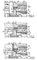
- Figures 1, 2, 4, 5, 6, 7 and 8 show an injection mould 1 for manufacturing disc-like plastic objects with a central hole.
- the mould comprises a first mould part 2, a second mould part 3 displaceable relative to this first mould part 2 by means of generally known first displacing means (not shown), which two mould parts 2, 3 are displaceable by means of first displacing means between a closed first position shown in figures 1, 2, 5, 6, 7, in which they bound together with a ring 5 a mould cavity 6 corresponding to the shape of an object for manufacture, and an open second position designated with 7 in which a formed object 8 can be taken out; a third mould part 4 (see also figure 3) which in an active position extends in the closed position of the first and second mould parts 3, 4 as according to figures 1, 2, 5, 6, 7 through the mould cavity 6 defined thereby and in the region of this mould cavity 6 has a shape corresponding to the shape of the central hole 9 of object 8, which third mould part 4 is axially displaceable with the first and second mould parts 2, 3 between said active position in which it forms
- An annular constriction 37 serves as stop for mould part 4.
- valve body 18 can have substantially the same shape as valve seat 16.
- the drawings show that the shape in question is a conical form with a top angle of about 20°.
- the channel 11 debouches in the region of valve 16, 18 into mould cavity 6 via an annular opening, at least in the active position shown in figure 6.
- the third mould part 4 has the shape of a torpedo, as shown clearly in figure 3, and has a generally elongate shape with three guide ribs 22, 23, 24, which are slidable over inner surface 17. Because ribs 22, 23, 24 extend over a substantial axial distance and fit with little clearance inside said cylindrical surface 17, the third mould part 3 is carried in easily slidable manner without substantial radial variation.
- Cooling means are selectively active in the centre zone of mould cavity 6. These consist of a cooling element 25 with cooling channel 26 formed integrally with first mould part 2 or separated therefrom in accordance with the annexed drawings.
- the front surface 27 of element 25 lies precisely in the same plane as front surface 28 of mould part 2.
- the effect of the operation of these cooling means 25, 26 is that in the situation according to figure 6 plastic flowing into mould cavity 6 is cooled, which is found to result in a greatly improved optical quality of the formed disc-like objects, this being particularly important in the case of transparent disc-like information carriers.
- Pressure cylinder 21 can be thermally coupled to a cooling channel 29.
- all surfaces of third mould part 4 and of channel 11 suitable for this purpose are provided with a coating which has anti-stick properties in respect of the plastic 20 flowing past, is heat-resistant, wear-resistant and reduces the friction between guide ribs 22, 23, 24 and surface 17.
- a coating which has anti-stick properties in respect of the plastic 20 flowing past, is heat-resistant, wear-resistant and reduces the friction between guide ribs 22, 23, 24 and surface 17.
- An example of such a coating is titanium nitride (TiN), diamond-like carbon (DLC) or the like.
- valve body 18 serving as valve body is connected in the manner shown particularly clearly in figure 3 to the rest of the third mould part 4 by means of a screw 30.
- the valve body can thus be replaced by another valve body and can moreover consist of a different material.
- the material of the valve body is a material which is a poor heat conductor, for instance a ceramic material.
- the fact that valve body 18 is exchangeable and connected releasably to the rest of the mould part 4 has the advantage that it can be replaced in the case of wear and can moreover be manufactured from a relatively expensive material without this substantially increasing the total cost of mould part 4, 18.
- Guide sleeve 10 is connected to cooling element 25 via a thermally insulating ring 31. Heating element 122 is thus thermally separated from cooling element 25.
- Heating element 122 is thus thermally separated from cooling element 25.
- Figure 5 shows the situation in which the mould is closed and mould cavity 6 is formed.
- FIG 6 shows the following phase in which the plastic 20 in channel 11 is placed under pressure, whereby valve body 18 is displaced to the situation shown in figure 6 in which valve 16, 18 is opened and the plastic is injected via an annular injection zone.
- cooling liquid flows through cooling channel 26 for cooling of front surface 27.
- a certain after-pressure is also exerted after injection.
- cooling liquid also flows through cooling channel 29.
- Figure 8 shows that for this purpose mould part 3 is displaced to the left as according to arrow 36 such that disc 8 can be taken out.
- stamper has been omitted from the drawing, i.e. a disc-like insert in the mould cavity in which the information for transferring onto the information carrier is displayed in negative form.
- Figure 9 shows a part of an injection mould 101 which forms part of the dual injection moulding unit 102 shown in figure 11.
- Mould 101 largely corresponds with mould 1 according to figure 2. An essential difference is the form of the helical guide ribs to be described hereinbelow.
- Mould 101 of figure 9 has a third mould part 103 with guide ribs 104, 105, 106 which, as shown, have a generally helical shape, are in angularly equidistant arrangement and have identical shapes.
- mould 101 In respect of mould 101 reference is otherwise made to mould 1 according to figure 2.
- Figure 10 shows the general torpedo-like third mould part 103.
- FIG 11 shows that the injection moulding unit 102 comprises two moulds of the type according to figure 9. These two moulds are therefore designated with the same reference numeral, i.e. 101. Attention is drawn to the fact that each of the two moulds comprises a pneumatic pusher unit 107 for urging third mould part 103 to a closed position as shown in figure 9 after the forming of a plastic object. In this position the conical widened portion 19 closes sealingly in the manner of a valve body against the correspondingly formed conical valve seat 16. For the sake of conciseness reference is otherwise made to figures 2, 4, 5, 6, 7 and 8 for the operation of mould 101.
- figure 12 shows a dual injection moulding unit 108 with two injection moulds 109, 110 in an embodiment other than that shown in figure 11 with reference to unit 102.
- each of the moulds 101 is provided with a third mould part 103 as according to figure 10.
- This mould part is slidingly shiftable in channel 111.
- the third mould part 112 is likewise axially shiftable but is guided slidably in the double hot-runner 114 via a continuous hole 113 by means of a guide stem 115 forming part of third mould part 112.
- the multiple hot-runner 114 connects with its inlet channel 115 in the same manner as shown in figure 1 onto a plastic-plasticizing and injecting unit of a per se known type.
- Inlet channel 115 branches into two channels 116, 117 respectively which each supply a part-flow of plastic to the respective moulds 101, 101 respectively 109, 110.
- the advantages in the embodiment of figure 12 may lie in the fact that the plastic flow in the direction of valve 16, 19 is influenced less and has more the character of a cylindrical jacket-like flow.
- a widened portion 118 acting as stop can further be positioned in very simple manner outside mould 109, 110.
- a drawback of the structure of figure 12 may be that the hot-runner is not fully closed, as is very much the case in the embodiment according to figures 1, 2, 9, and that plastic leakage can therefore occur as a result of the very high injection pressures.
Landscapes
- Engineering & Computer Science (AREA)
- Manufacturing & Machinery (AREA)
- Mechanical Engineering (AREA)
- Moulds For Moulding Plastics Or The Like (AREA)
- Injection Moulding Of Plastics Or The Like (AREA)
- Biological Depolymerization Polymers (AREA)
Applications Claiming Priority (5)
| Application Number | Priority Date | Filing Date | Title |
|---|---|---|---|
| NL1008579A NL1008579C2 (nl) | 1998-03-13 | 1998-03-13 | Spuitgietmatrijs voor schijfvormige kunststof voorwerpen. |
| NL1008579 | 1998-03-13 | ||
| NL1010868 | 1998-12-22 | ||
| NL1010868A NL1010868C2 (nl) | 1998-12-22 | 1998-12-22 | Spuitgietmatrijs voor schijfvormige kunststof voorwerpen en spuitgieteenheid. |
| PCT/NL1999/000140 WO1999046108A1 (en) | 1998-03-13 | 1999-03-15 | Injection mould for disc-like plastic objects and multiple injection moulding unit |
Publications (2)
| Publication Number | Publication Date |
|---|---|
| EP1062083A1 EP1062083A1 (en) | 2000-12-27 |
| EP1062083B1 true EP1062083B1 (en) | 2005-09-21 |
Family
ID=26642768
Family Applications (1)
| Application Number | Title | Priority Date | Filing Date |
|---|---|---|---|
| EP99910864A Expired - Lifetime EP1062083B1 (en) | 1998-03-13 | 1999-03-15 | Injection mould for disc-like plastic objects and multiple injection moulding unit |
Country Status (9)
| Country | Link |
|---|---|
| US (1) | US6461143B1 (da) |
| EP (1) | EP1062083B1 (da) |
| JP (1) | JP2002505967A (da) |
| AT (1) | ATE304930T1 (da) |
| DE (1) | DE69927362T2 (da) |
| DK (1) | DK1062083T3 (da) |
| ES (1) | ES2245093T3 (da) |
| PT (1) | PT1062083E (da) |
| WO (1) | WO1999046108A1 (da) |
Families Citing this family (4)
| Publication number | Priority date | Publication date | Assignee | Title |
|---|---|---|---|---|
| CA2317779A1 (en) * | 2000-09-06 | 2002-03-06 | Mold-Masters Limited | Valve gate assembly for injection molding |
| KR100587322B1 (ko) * | 2003-01-14 | 2006-06-08 | 엘지전자 주식회사 | 고강성 광 디스크의 제조 방법 |
| DE202005020412U1 (de) * | 2005-12-28 | 2007-05-10 | Günther Heisskanaltechnik Gmbh | Betätigungsvorrichtung für Verschlußnadeln in Spritzgießvorrichtungen mit Nadelverschlußdüsen |
| DE102008036203B4 (de) | 2008-08-02 | 2012-09-20 | Optimal Media Production Gmbh | Spritzgusswerkzeug zur Herstellung scheibenförmiger Aufzeichnungsträger |
Family Cites Families (18)
| Publication number | Priority date | Publication date | Assignee | Title |
|---|---|---|---|---|
| US2918086A (en) | 1948-10-18 | 1959-12-22 | Maschinefabrik Surth Zweignied | Valve devices |
| US3642418A (en) | 1970-04-29 | 1972-02-15 | Holdt J W Von | Heated feeder system for diecasting apparatus |
| US4077756A (en) | 1976-09-08 | 1978-03-07 | Peerless Machine & Tool Corporation | Injection molding extrusion mixer |
| US4340353A (en) | 1980-10-31 | 1982-07-20 | Discovision Associates | Hot sprue valve assembly for an injection molding machine |
| CA1165525A (en) | 1981-02-12 | 1984-04-17 | Jobst U. Gellert | Heated nozzle bushing with fixed spiral blade |
| US4394117A (en) | 1981-06-10 | 1983-07-19 | Discovision Associates | Hot sprue sleeve valve assembly for an injection molding machine |
| JPS5851126A (ja) | 1981-09-22 | 1983-03-25 | Toshiba Mach Co Ltd | 金型ゲ−トバランス制御方法およびその装置 |
| US4391579A (en) * | 1981-09-23 | 1983-07-05 | Discovision Associates | Hot sprue valve assembly for an injection molding machine |
| CA1193817A (en) | 1983-02-24 | 1985-09-24 | Jobst U. Gellert | Injection molding core ring gate system |
| JPS61229520A (ja) | 1985-04-05 | 1986-10-13 | Hitachi Ltd | 多数個取り用射出圧縮成形金型装置 |
| JPS61272119A (ja) | 1985-05-27 | 1986-12-02 | Shinagawa Refract Co Ltd | 可塑物の成形装置 |
| JPS6248519A (ja) | 1985-08-28 | 1987-03-03 | Toyoda Gosei Co Ltd | ホツトランナノズル |
| US4808106A (en) * | 1987-11-19 | 1989-02-28 | Holdt J W Von | Flex gate |
| JPH0710546B2 (ja) | 1990-11-09 | 1995-02-08 | プラストロン株式会社 | 加熱装置を有するゲート装置 |
| CA2057438C (en) * | 1991-12-11 | 2005-02-08 | Jobst Ulrich Gellert | Injection molding sealing collar with a central hot tip shaft |
| SE9200073L (sv) | 1992-01-13 | 1993-07-14 | Hans Mueller | Anordning vid reglernaalscylinder |
| US5783234A (en) | 1996-07-25 | 1998-07-21 | Husky Injection Molding Systems Ltd. | Hot runner valve gate for eliminating unidirectional molecular orientation and weld lines from solidified resin used for forming molded articles |
| US5785915A (en) * | 1996-09-13 | 1998-07-28 | Osuna-Diaz; Jesus M. | Injection molding with annular gate and sleeve shutoff valve |
-
1999
- 1999-03-15 DE DE69927362T patent/DE69927362T2/de not_active Expired - Fee Related
- 1999-03-15 DK DK99910864T patent/DK1062083T3/da active
- 1999-03-15 PT PT99910864T patent/PT1062083E/pt unknown
- 1999-03-15 ES ES99910864T patent/ES2245093T3/es not_active Expired - Lifetime
- 1999-03-15 US US09/622,668 patent/US6461143B1/en not_active Expired - Fee Related
- 1999-03-15 JP JP2000535503A patent/JP2002505967A/ja active Pending
- 1999-03-15 EP EP99910864A patent/EP1062083B1/en not_active Expired - Lifetime
- 1999-03-15 AT AT99910864T patent/ATE304930T1/de not_active IP Right Cessation
- 1999-03-15 WO PCT/NL1999/000140 patent/WO1999046108A1/en not_active Ceased
Also Published As
| Publication number | Publication date |
|---|---|
| DK1062083T3 (da) | 2006-01-30 |
| ATE304930T1 (de) | 2005-10-15 |
| JP2002505967A (ja) | 2002-02-26 |
| DE69927362D1 (de) | 2006-02-02 |
| DE69927362T2 (de) | 2006-07-13 |
| WO1999046108A1 (en) | 1999-09-16 |
| ES2245093T3 (es) | 2005-12-16 |
| EP1062083A1 (en) | 2000-12-27 |
| PT1062083E (pt) | 2005-11-30 |
| US6461143B1 (en) | 2002-10-08 |
Similar Documents
| Publication | Publication Date | Title |
|---|---|---|
| US4391579A (en) | Hot sprue valve assembly for an injection molding machine | |
| US7527490B2 (en) | Coinjection molding apparatus and related hot-runner nozzle | |
| CA2255341C (en) | Valve-type nozzle | |
| EP0936047B1 (en) | Injection molding method, injection mold, and valve gate device | |
| KR830007265A (ko) | 사출성형기의 열탕구 슬리이브 밸브조립체 | |
| CA2244762C (en) | Valve gate assembly | |
| AU2003303943A1 (en) | Injection molding nozzle | |
| JP3452988B2 (ja) | バルブゲート式金型装置 | |
| CA2095011A1 (en) | Injection mould | |
| EP1062083B1 (en) | Injection mould for disc-like plastic objects and multiple injection moulding unit | |
| US7497681B2 (en) | Needle valve nozzle | |
| US20190016031A1 (en) | Apparatus for injection moulding of plastic materials | |
| US20040009260A1 (en) | Injection-moulding tool for the production of information carriers in disc form | |
| CN108883560B (zh) | 注塑模具 | |
| JP2001503689A (ja) | 射出成形のための装置及びその方法 | |
| JP3859037B2 (ja) | 中空製品用射出成形金型 | |
| US6830447B2 (en) | Valve gate assembly for injection molding | |
| US20250262808A1 (en) | Injection mold component | |
| NL1010868C2 (nl) | Spuitgietmatrijs voor schijfvormige kunststof voorwerpen en spuitgieteenheid. | |
| NL1011564C2 (nl) | Spuitgietmatrijs voor schijfvormige kunststof voorwerpen en meervoudige spuitgieteenheid. | |
| JP3948791B2 (ja) | 射出成形金型 | |
| JP3457715B2 (ja) | 成形金型用ノズルホルダユニット | |
| JP2008030297A (ja) | 射出成形金型 | |
| JP2003245960A (ja) | 成形用金型装置 | |
| CN106393593A (zh) | 一种可防针阀打偏的注射塑料模具 |
Legal Events
| Date | Code | Title | Description |
|---|---|---|---|
| PUAI | Public reference made under article 153(3) epc to a published international application that has entered the european phase |
Free format text: ORIGINAL CODE: 0009012 |
|
| 17P | Request for examination filed |
Effective date: 20000816 |
|
| AK | Designated contracting states |
Kind code of ref document: A1 Designated state(s): AT BE CH DE DK ES FR GB IE IT LI LU NL PT SE |
|
| 17Q | First examination report despatched |
Effective date: 20010807 |
|
| GRAP | Despatch of communication of intention to grant a patent |
Free format text: ORIGINAL CODE: EPIDOSNIGR1 |
|
| GRAS | Grant fee paid |
Free format text: ORIGINAL CODE: EPIDOSNIGR3 |
|
| GRAA | (expected) grant |
Free format text: ORIGINAL CODE: 0009210 |
|
| AK | Designated contracting states |
Kind code of ref document: B1 Designated state(s): AT BE CH DE DK ES FR GB IE IT LI LU NL PT SE |
|
| REG | Reference to a national code |
Ref country code: GB Ref legal event code: FG4D |
|
| REG | Reference to a national code |
Ref country code: SE Ref legal event code: TRGR |
|
| REG | Reference to a national code |
Ref country code: CH Ref legal event code: NV Representative=s name: ARNOLD & SIEDSMA AG Ref country code: CH Ref legal event code: EP |
|
| REG | Reference to a national code |
Ref country code: IE Ref legal event code: FG4D |
|
| REF | Corresponds to: |
Ref document number: 69927362 Country of ref document: DE Date of ref document: 20051027 Kind code of ref document: P |
|
| REG | Reference to a national code |
Ref country code: ES Ref legal event code: FG2A Ref document number: 2245093 Country of ref document: ES Kind code of ref document: T3 |
|
| REG | Reference to a national code |
Ref country code: DK Ref legal event code: T3 |
|
| REF | Corresponds to: |
Ref document number: 69927362 Country of ref document: DE Date of ref document: 20060202 Kind code of ref document: P |
|
| ET | Fr: translation filed | ||
| PLBE | No opposition filed within time limit |
Free format text: ORIGINAL CODE: 0009261 |
|
| STAA | Information on the status of an ep patent application or granted ep patent |
Free format text: STATUS: NO OPPOSITION FILED WITHIN TIME LIMIT |
|
| 26N | No opposition filed |
Effective date: 20060622 |
|
| PGFP | Annual fee paid to national office [announced via postgrant information from national office to epo] |
Ref country code: DK Payment date: 20080331 Year of fee payment: 10 |
|
| PGFP | Annual fee paid to national office [announced via postgrant information from national office to epo] |
Ref country code: NL Payment date: 20080331 Year of fee payment: 10 Ref country code: LU Payment date: 20080326 Year of fee payment: 10 Ref country code: IT Payment date: 20080328 Year of fee payment: 10 Ref country code: GB Payment date: 20080331 Year of fee payment: 10 |
|
| PGFP | Annual fee paid to national office [announced via postgrant information from national office to epo] |
Ref country code: AT Payment date: 20080327 Year of fee payment: 10 |
|
| PGFP | Annual fee paid to national office [announced via postgrant information from national office to epo] |
Ref country code: ES Payment date: 20080331 Year of fee payment: 10 Ref country code: DE Payment date: 20080331 Year of fee payment: 10 Ref country code: CH Payment date: 20080328 Year of fee payment: 10 |
|
| PGFP | Annual fee paid to national office [announced via postgrant information from national office to epo] |
Ref country code: BE Payment date: 20080401 Year of fee payment: 10 |
|
| PGFP | Annual fee paid to national office [announced via postgrant information from national office to epo] |
Ref country code: SE Payment date: 20080331 Year of fee payment: 10 Ref country code: PT Payment date: 20080828 Year of fee payment: 10 |
|
| PGFP | Annual fee paid to national office [announced via postgrant information from national office to epo] |
Ref country code: IE Payment date: 20080829 Year of fee payment: 10 Ref country code: FR Payment date: 20080326 Year of fee payment: 10 |
|
| REG | Reference to a national code |
Ref country code: PT Ref legal event code: MM4A Free format text: LAPSE DUE TO NON-PAYMENT OF FEES Effective date: 20090915 |
|
| BERE | Be: lapsed |
Owner name: *AXXICON MOULDS EINDHOVEN B.V. Effective date: 20090331 |
|
| PG25 | Lapsed in a contracting state [announced via postgrant information from national office to epo] |
Ref country code: PT Free format text: LAPSE BECAUSE OF NON-PAYMENT OF DUE FEES Effective date: 20090915 Ref country code: AT Free format text: LAPSE BECAUSE OF NON-PAYMENT OF DUE FEES Effective date: 20090315 |
|
| REG | Reference to a national code |
Ref country code: CH Ref legal event code: PL |
|
| REG | Reference to a national code |
Ref country code: DK Ref legal event code: EBP |
|
| EUG | Se: european patent has lapsed | ||
| GBPC | Gb: european patent ceased through non-payment of renewal fee |
Effective date: 20090315 |
|
| NLV4 | Nl: lapsed or anulled due to non-payment of the annual fee |
Effective date: 20091001 |
|
| REG | Reference to a national code |
Ref country code: FR Ref legal event code: ST Effective date: 20091130 |
|
| REG | Reference to a national code |
Ref country code: IE Ref legal event code: MM4A |
|
| PG25 | Lapsed in a contracting state [announced via postgrant information from national office to epo] |
Ref country code: LI Free format text: LAPSE BECAUSE OF NON-PAYMENT OF DUE FEES Effective date: 20090331 Ref country code: IE Free format text: LAPSE BECAUSE OF NON-PAYMENT OF DUE FEES Effective date: 20090316 Ref country code: DE Free format text: LAPSE BECAUSE OF NON-PAYMENT OF DUE FEES Effective date: 20091001 Ref country code: CH Free format text: LAPSE BECAUSE OF NON-PAYMENT OF DUE FEES Effective date: 20090331 |
|
| PG25 | Lapsed in a contracting state [announced via postgrant information from national office to epo] |
Ref country code: BE Free format text: LAPSE BECAUSE OF NON-PAYMENT OF DUE FEES Effective date: 20090331 Ref country code: NL Free format text: LAPSE BECAUSE OF NON-PAYMENT OF DUE FEES Effective date: 20091001 |
|
| PG25 | Lapsed in a contracting state [announced via postgrant information from national office to epo] |
Ref country code: GB Free format text: LAPSE BECAUSE OF NON-PAYMENT OF DUE FEES Effective date: 20090315 Ref country code: FR Free format text: LAPSE BECAUSE OF NON-PAYMENT OF DUE FEES Effective date: 20091123 Ref country code: DK Free format text: LAPSE BECAUSE OF NON-PAYMENT OF DUE FEES Effective date: 20090331 |
|
| REG | Reference to a national code |
Ref country code: ES Ref legal event code: FD2A Effective date: 20090316 |
|
| PG25 | Lapsed in a contracting state [announced via postgrant information from national office to epo] |
Ref country code: ES Free format text: LAPSE BECAUSE OF NON-PAYMENT OF DUE FEES Effective date: 20090316 |
|
| PG25 | Lapsed in a contracting state [announced via postgrant information from national office to epo] |
Ref country code: IT Free format text: LAPSE BECAUSE OF NON-PAYMENT OF DUE FEES Effective date: 20090315 |
|
| PG25 | Lapsed in a contracting state [announced via postgrant information from national office to epo] |
Ref country code: LU Free format text: LAPSE BECAUSE OF NON-PAYMENT OF DUE FEES Effective date: 20090315 |
|
| PG25 | Lapsed in a contracting state [announced via postgrant information from national office to epo] |
Ref country code: SE Free format text: LAPSE BECAUSE OF NON-PAYMENT OF DUE FEES Effective date: 20090316 |