EP1061184A2 - Vorrichtung zum erfassen eines laserstrahls - Google Patents
Vorrichtung zum erfassen eines laserstrahls Download PDFInfo
- Publication number
- EP1061184A2 EP1061184A2 EP00112651A EP00112651A EP1061184A2 EP 1061184 A2 EP1061184 A2 EP 1061184A2 EP 00112651 A EP00112651 A EP 00112651A EP 00112651 A EP00112651 A EP 00112651A EP 1061184 A2 EP1061184 A2 EP 1061184A2
- Authority
- EP
- European Patent Office
- Prior art keywords
- laser beam
- detecting device
- sensor
- construction machine
- beam detecting
- Prior art date
- Legal status (The legal status is an assumption and is not a legal conclusion. Google has not performed a legal analysis and makes no representation as to the accuracy of the status listed.)
- Granted
Links
Images


Classifications
-
- G—PHYSICS
- G01—MEASURING; TESTING
- G01C—MEASURING DISTANCES, LEVELS OR BEARINGS; SURVEYING; NAVIGATION; GYROSCOPIC INSTRUMENTS; PHOTOGRAMMETRY OR VIDEOGRAMMETRY
- G01C15/00—Surveying instruments or accessories not provided for in groups G01C1/00 - G01C13/00
- G01C15/002—Active optical surveying means
- G01C15/004—Reference lines, planes or sectors
- G01C15/006—Detectors therefor
-
- E—FIXED CONSTRUCTIONS
- E02—HYDRAULIC ENGINEERING; FOUNDATIONS; SOIL SHIFTING
- E02F—DREDGING; SOIL-SHIFTING
- E02F9/00—Component parts of dredgers or soil-shifting machines, not restricted to one of the kinds covered by groups E02F3/00 - E02F7/00
- E02F9/26—Indicating devices
Definitions
- the present invention relates to a laser beam detecting device for detecting a laser beam emitted from a laser beam generator such as a rotating laser which is used in a land formation work or the like.
- a laser beam detecting device is installed in the vicinity of a leveling implement of a construction machine. Therefore, wiring which uses cords is an obstacle to the installation of the laser beam detecting device. Moreover, it is very dangerous to be caught by the leveling implement and therefore, for avoiding such a danger, it is necessary to exercise a great care in installing the laser beam detecting device. Thus, the work for installing the laser beam detecting device has so far been very troublesome.
- the battery will soon run down.
- the operation of a power supply for the entire device is switched over between ON and OFF, depending on whether a laser beam is incident or not.
- the operation mode of the device becomes "sleep mode" and the device stands by.
- the sleep mode is canceled and the laser beam detecting device assumes an operating state.
- the conventional laser beam detecting device which detects the incidence of laser beam is required to be always in a state capable of detecting a laser beam. That is, the beam sensor must be kept ON.
- the beam sensor since the beam sensor has a function of detecting a laser beam incidence position, it is provided with an analog circuit having many channels, resulting in power consumption as much as about five-sixths of that of the device.
- the laser beam detecting device detects a laser beam which is emitted from a laser beam generator and which forms a reference plane.
- a beam sensor used in the laser beam detecting device for detecting a laser beam is connected to a power supply.
- the power supply is turned OFF automatically.
- vibration of the construction machine is detected by a vibration sensor, thereby tuning ON the power supply for the beam sensor.
- the vibration sensor is constituted by a chip capacitor.
- the power supply for the beam sensor is controlled by a microcomputer and the state of operation of the construction machine is detected by the vibration sensor.
- a laser beam detecting device in a preferred mode of the present invention is fixed to a predetermined position of, for example, an arm of a construction machine such as an excavator through a magnet or a clamp.
- the predetermined position indicates a position which permits an offset to be clarified between a leveling implement (especially a tip end thereof) such as a bucket which forms a working surface and the predetermined position.
- a reference plane is formed with a laser beam emitted from a laser beam generator such as a rotating laser.
- the laser beam detecting device is mounted above the leveling implement of the construction machine so that a reference position is established at a predetermined height with respect to a portion of the leveling implement which portion forms a working surface.
- a laser beam is detected by the beam sensor, and in accordance with a deviation (in the vertical direction) between an incidence position of the laser beam and the reference position of the device, the direction in which the leveling implement is to be moved is instructed to an operator of the construction machine on a display (display portion).
- the beam sensor is mounted above the leveling implement, a laser beam as a reference is detected by the beam sensor, and information based on the beam detection is displayed on a display.
- a plurality of reference positions are established in a detection range of a beam receiving portion of the beam sensor and one of the reference positions is made a standard position, while the other reference positions are made offset positions.
- First and second offset positions are established respectively above and below the standard position.
- a display display portion indicating in which of standard and offset positions the laser beam detection is being conducted.
- an incidence position of a laser beam with respect to a reference position is detected, and on the basis of the detected beam incidence position, the direction in which the leveling implement is to be moved, as well as the distance at which the leveling implement is to be moved, are indicated to the operator.
- the laser beam detecting device is attached, at the back of its body, to a predetermined position (e.g., arm) of the construction machine removably with screws or the like.
- the laser beam detecting device may be fixed magnetically to the leveling implement of the construction machine.
- a strong magnetic force can be obtained by holding plural magnets in between plural net plates.
- the net plates are in contact with the leveling implement.
- the net plates are each adapted to move slightly, they can fix the magnets securely and prevent them from coming off even if the magnet surfaces are somewhat uneven or even under an abrupt shock.
- the laser beam detecting device may also be fixed to a pole or the like which is fixed to the leveling implement. In this case, a clamp is often used for the fixing.
- Fig. 1 is a plan view showing a state in which a civil engineering work is being carried out by a shovel car 2 equipped with a laser beam detecting device 1 for a construction machine according to the present invention.
- the reference numeral 10 denotes a detection range of a leveled land (formed land surface).
- a reference position 11 of the leveled land is a standard position.
- a rotating laser 4 is installed at a predetermined position of the leveled land or a land adjacent thereto through a tripod 3.
- a laser beam P emitted from the rotating laser 4 forms a reference plane.
- the laser beam detecting device 1 which is for indicating an appropriate height to an operator on the construction machine 2 in cooperation with the laser beam P, is attached to an arm portion 2a of the construction machine.
- the laser beam detecting device 1 has a beam sensor 5 for detecting the laser beam P and a display 6 for indicating an offset from the appropriate height to the operator on the construction machine 2 on the basis of the result of the detection.
- the beam sensor 5 is disposed at a front position of the laser beam detecting device 1. In a detection range of the beam sensor 5 are disposed an upper range R1 and a lower range R2 with respect to a center C. The ranges R1 and R2 are each about 10 cm in size. A laser beam is transmitted from left to right in Fig. 2 and can enter the detection range of the beam sensor 5.
- a large number of light emitting elements e.g., LEDs
- Nine rows are set in the vertical direction.
- two, one, three, one, three, one, three, one, three, one, and two light emitting elements 61 are arranged in the nine rows, respectively.
- there are three rows each including three light emitting elements, all of which represent reference positions and of which the central row represents a standard position, while the upper and lower rows represent first and second offset positions, respectively.
- Marks 63, 64, and 65 which are light emitting elements, are arranged correspondingly to the rows indicative of those reference positions.
- the reference numeral 66 denotes a button for selecting any one of the mark 65 as the standard position and the marks 63 and 64 as the first and second offset positions.
- the positions of the marks 63, 64, and 65 which are set (i.e., go ON) at every depression of the button 66 by the operator, change rotationwise.
- the numeral 67 denotes a power switch for ON-OFF switching.
- Fig. 3 shows an example of position display in a normal state, in which the mark 65 at the standard position is ON.
- the laser beam P lies below the reference position (standard position) S of the beam sensor 5.
- the laser beam P lies above the reference position (standard position) S.
- the four light emitting elements 61 emit light in two modes (three light emitting elements which constitute a triangular shape and one light emitting element present at the established reference position), urging the operator to move the arm.
- the light emitting element present at the reference position serves as a reference indicating the width and direction of offset with respect to the three light emitting elements which constitute a triangular shape.
- a plurality of light emitting elements located at the reference position may be turned ON so as to represent a reference line.
- the light emitting elements 61 which have emitted light in a triangular shape go OFF and a transverse row of three light emitting elements 61 newly located at the reference position emit light, indicating completion of the movement.
- the light emitting elements 61 in a triangular form and the light emitting elements 61 located in the apex direction of the triangle are turned ON in an alternate manner, thereby making it easier to visually check the direction of offset.
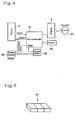
- Fig. 4 shows a system for controlling the beam sensor 5 and the display 6.
- the beam sensor 5 for detecting the laser beam P has an analog circuit (not shown).
- a power supply 83 for the beam sensor is controlled by a microcomputer 81 which is incorporated in the body of the laser beam detecting device.
- the microcomputer 81 judges that no construction work is being conducted, then sets the operation mode to a sleep mode and turns OFF the power supply 83 for the beam sensor 5.
- a sleep reset signal which is inputted to the microcomputer 81 from a vibration sensor 82, becomes effective. This signal is for canceling the sleep state and is applied to the microcomputer 81 when vibration is detected by the vibration sensor 82.
- the vibration sensor 82 is power-supplied by the power supply 83, which is kept ON.
- the power consumption of the entire device is 300 mW in operation and is 49 mW in the sleep state.
- the analog circuit in the beam sensor 5 consumes electric power about five-sixths of the electric power consumed by the entire detecting device and thus the power saving effect in the sleep mode is high.
- the reason for such a large power consumption of the beam sensor 5 is that the beam sensor requires a large number of circuit channels for detecting a laser beam incidence position and that therefore a large electric power is consumed inevitably.
- the power supply 83 there are used four UM-3 charging cells of NiMH type.
- the ordinary type of dry cells or a battery may also be used.
- Fig. 5 shows an example of the vibration sensor 82.
- the vibration sensor 82 is of a configuration similar to the configuration of a chip capacitor and possesses a characteristic such that a weak current is generated upon imposition of vibration on plural capacitors 91.
- the power consumption of the vibration sensor 82 is fairly weak and is 1 mW or so, even including the amplifier circuit.
- the vibration sensor 82 used in this embodiment is "PKGS-45LB-TC"(a product of Murata Manufacturing Company Limited).
- the numeral 84 denotes an operator and numeral 66 denotes a switch for the microcomputer 81.
- vibration sensor 82 permits reduction of the power consumption in the entire laser beam detecting device. Particularly, where a battery or the like is used as a drive source, there no longer is any fear that the work may be interrupted by exhaustion of the battery, thus enhancing the working efficiency.
- That the device becomes light is advantageous in that the device becomes less likely to come off under a sudden shock and becomes easier to carry for installation in a construction machine.
- vibration sensor permits the device to be controlled accurately in conformity with the operating condition of the construction machine in which it is installed.
Landscapes
- Engineering & Computer Science (AREA)
- Mining & Mineral Resources (AREA)
- Civil Engineering (AREA)
- General Engineering & Computer Science (AREA)
- Structural Engineering (AREA)
- Physics & Mathematics (AREA)
- General Physics & Mathematics (AREA)
- Radar, Positioning & Navigation (AREA)
- Remote Sensing (AREA)
- Component Parts Of Construction Machinery (AREA)
- Operation Control Of Excavators (AREA)
- Measurement Of Mechanical Vibrations Or Ultrasonic Waves (AREA)
- Direct Current Feeding And Distribution (AREA)
- Photometry And Measurement Of Optical Pulse Characteristics (AREA)
- Lasers (AREA)
Applications Claiming Priority (2)
| Application Number | Priority Date | Filing Date | Title |
|---|---|---|---|
| JP16836999A JP4198826B2 (ja) | 1999-06-15 | 1999-06-15 | レーザー光検出装置 |
| JP16836999 | 1999-06-15 |
Publications (3)
| Publication Number | Publication Date |
|---|---|
| EP1061184A2 true EP1061184A2 (de) | 2000-12-20 |
| EP1061184A3 EP1061184A3 (de) | 2002-02-06 |
| EP1061184B1 EP1061184B1 (de) | 2003-08-13 |
Family
ID=15866825
Family Applications (1)
| Application Number | Title | Priority Date | Filing Date |
|---|---|---|---|
| EP00112651A Expired - Lifetime EP1061184B1 (de) | 1999-06-15 | 2000-06-15 | Vorrichtung zum erfassen eines laserstrahls |
Country Status (4)
| Country | Link |
|---|---|
| US (1) | US6480264B1 (de) |
| EP (1) | EP1061184B1 (de) |
| JP (1) | JP4198826B2 (de) |
| DE (1) | DE60004440T2 (de) |
Families Citing this family (5)
| Publication number | Priority date | Publication date | Assignee | Title |
|---|---|---|---|---|
| JP4920229B2 (ja) * | 2005-09-30 | 2012-04-18 | 株式会社トプコン | レーザレベル検出システム |
| JP5226963B2 (ja) | 2007-03-06 | 2013-07-03 | 株式会社トプコン | レーザ測定システム |
| JP4920467B2 (ja) | 2007-03-22 | 2012-04-18 | 株式会社トプコン | レーザ測定システムに於ける省電力制御方法及びレーザ測定システム |
| CN105004329A (zh) * | 2015-08-10 | 2015-10-28 | 胡仲春 | 一种用于铁路顶进涵施工的纠偏报警装置 |
| CN105300365B (zh) * | 2015-11-24 | 2018-05-08 | 广州市盾建地下工程有限公司 | 联络通道开挖定向装置及其定向方法 |
Family Cites Families (8)
| Publication number | Priority date | Publication date | Assignee | Title |
|---|---|---|---|---|
| JPS54109529A (en) * | 1978-02-15 | 1979-08-28 | Nippon Denso Co Ltd | Ignition timing controller for internal combustion engine |
| US4642618A (en) * | 1985-07-23 | 1987-02-10 | Ibm Corporation | Tool failure detector |
| EP0262764A1 (de) | 1986-09-30 | 1988-04-06 | Spectra-Physics, Inc. | Höhenanzeigesystem für ein grosses Erdbearbeitungsgerät |
| US4945221A (en) * | 1987-04-24 | 1990-07-31 | Laser Alignment, Inc. | Apparatus and method for controlling a hydraulic excavator |
| EP0560351B1 (de) * | 1992-03-13 | 1997-12-29 | Matsushita Electric Industrial Co., Ltd. | Gerät zur Feststellung der Anwesenheit einer Person und Sicherheits-Steuerung |
| JPH08122077A (ja) * | 1994-10-20 | 1996-05-17 | Fuji Photo Optical Co Ltd | 位置計測作図装置のターゲット |
| JP3670075B2 (ja) * | 1996-03-06 | 2005-07-13 | 株式会社トプコン | 適正高さ表示装置 |
| JP3827764B2 (ja) | 1996-03-19 | 2006-09-27 | 株式会社トプコン | 建設機械用レーザー光検出表示装置 |
-
1999
- 1999-06-15 JP JP16836999A patent/JP4198826B2/ja not_active Expired - Fee Related
-
2000
- 2000-06-15 DE DE60004440T patent/DE60004440T2/de not_active Expired - Lifetime
- 2000-06-15 EP EP00112651A patent/EP1061184B1/de not_active Expired - Lifetime
- 2000-06-15 US US09/594,613 patent/US6480264B1/en not_active Expired - Lifetime
Also Published As
| Publication number | Publication date |
|---|---|
| JP4198826B2 (ja) | 2008-12-17 |
| EP1061184B1 (de) | 2003-08-13 |
| EP1061184A3 (de) | 2002-02-06 |
| US6480264B1 (en) | 2002-11-12 |
| DE60004440D1 (de) | 2003-09-18 |
| JP2000356517A (ja) | 2000-12-26 |
| DE60004440T2 (de) | 2004-06-24 |
Similar Documents
| Publication | Publication Date | Title |
|---|---|---|
| US6665067B2 (en) | Laser beam detecting device for a construction machine | |
| ES2638648T3 (es) | Procedimiento para cargar un robot de servicio | |
| KR102081543B1 (ko) | 안전사고 방지용 스마트 기울임 경광 장치 및 그 동작방법 | |
| US20130074352A1 (en) | Laser Line Generator Having Three Intersecting Light Planes | |
| US11932517B2 (en) | Crane and device for controlling same | |
| EP1061184B1 (de) | Vorrichtung zum erfassen eines laserstrahls | |
| EP2939514B1 (de) | Rasenmähroboter und Steuerungsverfahren dafür | |
| JP3670075B2 (ja) | 適正高さ表示装置 | |
| JP2020509724A (ja) | 再充電可能なバッテリパック | |
| US12351050B2 (en) | Station and power supply device of autonomous travel work machine | |
| WO2021098868A1 (zh) | 固定装置、自主作业系统及固定装置的安装方法 | |
| US20060124323A1 (en) | Work linkage position determining system | |
| US20050258409A1 (en) | Vehicle jack positioning device and method | |
| KR20190047614A (ko) | 작업 기계 | |
| US7484907B2 (en) | Solar energy lane marking system | |
| WO2025230646A1 (en) | Aerial basket tool apron with integrated power system | |
| CN106049230A (zh) | 一种基于磁场的盲道以及与盲道配合使用的盲人探测棒 | |
| CN112189173A (zh) | 自动工作系统和自移动设备控制方法 | |
| KR102623036B1 (ko) | 정밀 야간 측량이 가능한 수준측량장치 | |
| US6470251B1 (en) | Light detector for multi-axis position control | |
| US10760229B2 (en) | Tilt sensing and indicating device for a containment plow | |
| CN213842180U (zh) | 第一信号发生装置及自主作业系统 | |
| CN223504805U (zh) | 一种麻将机的控制装置及麻将机 | |
| US20020190197A1 (en) | Photodetection device | |
| US20240429861A1 (en) | Solar panel with indicators |
Legal Events
| Date | Code | Title | Description |
|---|---|---|---|
| PUAI | Public reference made under article 153(3) epc to a published international application that has entered the european phase |
Free format text: ORIGINAL CODE: 0009012 |
|
| AK | Designated contracting states |
Kind code of ref document: A2 Designated state(s): DE SE Kind code of ref document: A2 Designated state(s): AT BE CH CY DE DK ES FI FR GB GR IE IT LI LU MC NL PT SE |
|
| AX | Request for extension of the european patent |
Free format text: AL;LT;LV;MK;RO;SI |
|
| PUAL | Search report despatched |
Free format text: ORIGINAL CODE: 0009013 |
|
| AK | Designated contracting states |
Kind code of ref document: A3 Designated state(s): AT BE CH CY DE DK ES FI FR GB GR IE IT LI LU MC NL PT SE |
|
| AX | Request for extension of the european patent |
Free format text: AL;LT;LV;MK;RO;SI |
|
| RIC1 | Information provided on ipc code assigned before grant |
Free format text: 7E 02F 3/43 A, 7G 01C 15/00 B, 7E 02F 3/84 B |
|
| 17P | Request for examination filed |
Effective date: 20020710 |
|
| AKX | Designation fees paid |
Free format text: DE SE |
|
| GRAH | Despatch of communication of intention to grant a patent |
Free format text: ORIGINAL CODE: EPIDOS IGRA |
|
| GRAH | Despatch of communication of intention to grant a patent |
Free format text: ORIGINAL CODE: EPIDOS IGRA |
|
| GRAH | Despatch of communication of intention to grant a patent |
Free format text: ORIGINAL CODE: EPIDOS IGRA |
|
| GRAA | (expected) grant |
Free format text: ORIGINAL CODE: 0009210 |
|
| AK | Designated contracting states |
Designated state(s): DE SE |
|
| REG | Reference to a national code |
Ref country code: IE Ref legal event code: FG4D |
|
| REF | Corresponds to: |
Ref document number: 60004440 Country of ref document: DE Date of ref document: 20030918 Kind code of ref document: P |
|
| REG | Reference to a national code |
Ref country code: SE Ref legal event code: TRGR |
|
| PLBE | No opposition filed within time limit |
Free format text: ORIGINAL CODE: 0009261 |
|
| STAA | Information on the status of an ep patent application or granted ep patent |
Free format text: STATUS: NO OPPOSITION FILED WITHIN TIME LIMIT |
|
| 26N | No opposition filed |
Effective date: 20040514 |
|
| REG | Reference to a national code |
Ref country code: IE Ref legal event code: MM4A |
|
| PGFP | Annual fee paid to national office [announced via postgrant information from national office to epo] |
Ref country code: DE Payment date: 20150609 Year of fee payment: 16 Ref country code: SE Payment date: 20150611 Year of fee payment: 16 |
|
| REG | Reference to a national code |
Ref country code: DE Ref legal event code: R119 Ref document number: 60004440 Country of ref document: DE |
|
| REG | Reference to a national code |
Ref country code: SE Ref legal event code: EUG |
|
| PG25 | Lapsed in a contracting state [announced via postgrant information from national office to epo] |
Ref country code: SE Free format text: LAPSE BECAUSE OF NON-PAYMENT OF DUE FEES Effective date: 20160616 |
|
| PG25 | Lapsed in a contracting state [announced via postgrant information from national office to epo] |
Ref country code: DE Free format text: LAPSE BECAUSE OF NON-PAYMENT OF DUE FEES Effective date: 20170103 |