EP1060902A2 - Procédé de transfert par pression de liquide pour des objets annulaires et produits ainsi décorés - Google Patents
Procédé de transfert par pression de liquide pour des objets annulaires et produits ainsi décorés Download PDFInfo
- Publication number
- EP1060902A2 EP1060902A2 EP00305158A EP00305158A EP1060902A2 EP 1060902 A2 EP1060902 A2 EP 1060902A2 EP 00305158 A EP00305158 A EP 00305158A EP 00305158 A EP00305158 A EP 00305158A EP 1060902 A2 EP1060902 A2 EP 1060902A2
- Authority
- EP
- European Patent Office
- Prior art keywords
- transfer
- workpiece
- liquid
- steering wheel
- pattern
- Prior art date
- Legal status (The legal status is an assumption and is not a legal conclusion. Google has not performed a legal analysis and makes no representation as to the accuracy of the status listed.)
- Granted
Links
Images


Classifications
-
- B—PERFORMING OPERATIONS; TRANSPORTING
- B41—PRINTING; LINING MACHINES; TYPEWRITERS; STAMPS
- B41M—PRINTING, DUPLICATING, MARKING, OR COPYING PROCESSES; COLOUR PRINTING
- B41M3/00—Printing processes to produce particular kinds of printed work, e.g. patterns
- B41M3/06—Veined printings; Fluorescent printings; Stereoscopic images; Imitated patterns, e.g. tissues, textiles
-
- B—PERFORMING OPERATIONS; TRANSPORTING
- B44—DECORATIVE ARTS
- B44C—PRODUCING DECORATIVE EFFECTS; MOSAICS; TARSIA WORK; PAPERHANGING
- B44C1/00—Processes, not specifically provided for elsewhere, for producing decorative surface effects
- B44C1/16—Processes, not specifically provided for elsewhere, for producing decorative surface effects for applying transfer pictures or the like
- B44C1/165—Processes, not specifically provided for elsewhere, for producing decorative surface effects for applying transfer pictures or the like for decalcomanias; sheet material therefor
- B44C1/175—Transfer using solvent
-
- B—PERFORMING OPERATIONS; TRANSPORTING
- B41—PRINTING; LINING MACHINES; TYPEWRITERS; STAMPS
- B41M—PRINTING, DUPLICATING, MARKING, OR COPYING PROCESSES; COLOUR PRINTING
- B41M3/00—Printing processes to produce particular kinds of printed work, e.g. patterns
- B41M3/12—Transfer pictures or the like, e.g. decalcomanias
-
- B—PERFORMING OPERATIONS; TRANSPORTING
- B41—PRINTING; LINING MACHINES; TYPEWRITERS; STAMPS
- B41M—PRINTING, DUPLICATING, MARKING, OR COPYING PROCESSES; COLOUR PRINTING
- B41M5/00—Duplicating or marking methods; Sheet materials for use therein
- B41M5/025—Duplicating or marking methods; Sheet materials for use therein by transferring ink from the master sheet
- B41M5/03—Duplicating or marking methods; Sheet materials for use therein by transferring ink from the master sheet by pressure
-
- B—PERFORMING OPERATIONS; TRANSPORTING
- B41—PRINTING; LINING MACHINES; TYPEWRITERS; STAMPS
- B41M—PRINTING, DUPLICATING, MARKING, OR COPYING PROCESSES; COLOUR PRINTING
- B41M5/00—Duplicating or marking methods; Sheet materials for use therein
- B41M5/025—Duplicating or marking methods; Sheet materials for use therein by transferring ink from the master sheet
- B41M5/035—Duplicating or marking methods; Sheet materials for use therein by transferring ink from the master sheet by sublimation or volatilisation of pre-printed design, e.g. sublistatic
- B41M5/0358—Duplicating or marking methods; Sheet materials for use therein by transferring ink from the master sheet by sublimation or volatilisation of pre-printed design, e.g. sublistatic characterised by the mechanisms or artifacts to obtain the transfer, e.g. the heating means, the pressure means or the transport means
-
- B—PERFORMING OPERATIONS; TRANSPORTING
- B44—DECORATIVE ARTS
- B44C—PRODUCING DECORATIVE EFFECTS; MOSAICS; TARSIA WORK; PAPERHANGING
- B44C1/00—Processes, not specifically provided for elsewhere, for producing decorative surface effects
- B44C1/16—Processes, not specifically provided for elsewhere, for producing decorative surface effects for applying transfer pictures or the like
- B44C1/165—Processes, not specifically provided for elsewhere, for producing decorative surface effects for applying transfer pictures or the like for decalcomanias; sheet material therefor
- B44C1/175—Transfer using solvent
- B44C1/1754—Decalcomanias provided with a layer being specially adapted to facilitate their release from a temporary carrier
-
- B—PERFORMING OPERATIONS; TRANSPORTING
- B60—VEHICLES IN GENERAL
- B60R—VEHICLES, VEHICLE FITTINGS, OR VEHICLE PARTS, NOT OTHERWISE PROVIDED FOR
- B60R13/00—Elements for body-finishing, identifying, or decorating; Arrangements or adaptations for advertising purposes
- B60R13/005—Manufacturers' emblems, name plates, bonnet ornaments, mascots or the like; Mounting means therefor
-
- B—PERFORMING OPERATIONS; TRANSPORTING
- B60—VEHICLES IN GENERAL
- B60R—VEHICLES, VEHICLE FITTINGS, OR VEHICLE PARTS, NOT OTHERWISE PROVIDED FOR
- B60R13/00—Elements for body-finishing, identifying, or decorating; Arrangements or adaptations for advertising purposes
- B60R13/02—Internal Trim mouldings ; Internal Ledges; Wall liners for passenger compartments; Roof liners
- B60R2013/0287—Internal Trim mouldings ; Internal Ledges; Wall liners for passenger compartments; Roof liners integrating other functions or accessories
Definitions
- This invention relates to a liquid pressure transfer method for applying a pattern for decoration to a loop-like member such as an annular member forming a closed loop like a steering wheel for an automobile or a U-shaped member forming an open loop like a chair back and a product decorated by the liquid pressure transfer method.
- a steering wheel for an automobile has a core made of a metal material so as to exhibit strength at a predetermined level or more.
- the core is provided therearound with a grip surface section, which is formed of a material such as a plastic material, a wooden material, a leather material or the like which is selected depending on desired requirements, such as operability of the steering wheel, decorative characteristics thereof and the like.
- a steering wheel provided thereon with a wooden surface section is evaluated as being a high-quality article, because it exhibits both satisfactory operability and decorative characteristics and requires considerable labor and time to manufacture.
- a conventional steering wheel made of a wooden material is manufactured by subjecting two wooden rod-like materials which are semicircular in section to a treatment by moistening, heating and the like, to thereby bend them into an annular shape and then bonding them to each other while interposing a core therebetween.
- the wooden materials are each so arranged that a straight grain extends in a circumferential direction of the steering wheel. Such arrangement of the straight grain permits a user to have a sense of security and a sense of reliability.
- the present invention has been made in view of the foregoing disadvantage of the prior art.
- a liquid pressure transfer method for a loop-like workpiece comprising the steps of: supporting a transfer film floatingly on a surface of a transfer liquid, said transfer film having a transfer pattern for decoration printed thereon; and downwardly immersing a workpiece in the transfer liquid to transfer the transfer pattern to a surface of the workpiece, to thereby decorate the workpiece, characterized in that: the workpiece is immersed in the transfer liquid such that a longitudinally extending portion extends through the surface of the transfer liquid at a transfer initiating site; the workpiece is contacted with the transfer film at the transfer initiating site substantially concurrently around the periphery of said longitudinally extending portion; the workpiece is adjusted at the transfer initiating site in a longitudinal direction of the workpiece so as to continuously downwardly immerse portions of the workpiece to be decorated in the transfer liquid, while an immersion attitude of the workpiece is maintained; and at least one of the workpiece and transfer film is moved relatively towards each other during immersion of the workpiece in the transfer
- a relative approach speed between the workpiece and the transfer film is set to permit an immersion rate of the workpiece and a feed rate of the transfer film to be substantially equal to each other.
- a deflection angle defined between a loop surface of the workpiece and a relative movement direction of the transfer film is set to be within a range of ⁇ 90°.
- an immersion attitude angle of a loop surface of the workpiece relative to the surface of the transfer liquid is set to be within a range of ⁇ 80° with respect to an upright position thereof.
- the workpiece is constituted by a steering wheel material formed to have a loop-like shape and provided on a part of a circumference thereof with a portion on which a transfer is not required.
- Initial immersion of the steering wheel material in the transfer liquid at the transfer initiating site is preferably started at the transfer not-required portion.
- the steering wheel is immersed in the transfer liquid as it is rotated while the immersion attitude of the steering wheel material at the transfer initiating site is permitted to be maintained during the transfer of the transfer pattern.
- the workpiece is constituted by a steering wheel material. Immersion of the steering wheel material progresses while a site is defined at which the steering wheel material is immersed in the transfer liquid on an upstream side in a transfer direction relative to the transfer film as the transfer initiating site, so that the transfer pattern has a joint line formed on a rear surface of the steering wheel material which is substantially invisible from a driver's seat when the steering wheel is mounted on a vehicle.
- the method of the present invention in at least preferred embodiments constructed as described above, when the steering wheel is applied as the loop-like workpiece, attains liquid pressure transfer printing which permits the transfer pattern to be satisfactorily applied onto the whole circumference of a section of the steering wheel taken substantially in the thickness direction thereof without causing any distortion of the applied pattern. Also in at least preferred embodiments, the method of the present invention permits the joint line of the transfer pattern to be positioned on the rear surface of the steering wheel which is substantially invisible from a driver's seat when the steering wheel is mounted on a vehicle, resulting in the transfer pattern such as a straight grain pattern, a fine check pattern or the like being increased in aesthetic characteristics. Further, in at least preferred embodiments, the present invention permits the deflection angle and immersion attitude angle to be optimumly set depending on a size of each of the transfer pattern and workpiece, a configuration thereof and the like.
- a decorated product having a decorative pattern applied thereto by subjecting a workpiece of a loop-like shape to liquid pressure transfer printing, wherein the workpiece is downwardly immersed in a transfer liquid which supports floatingly on a surface thereof a transfer film having a transfer pattern for decoration printed thereon, so that the transfer pattern is applied to the workpiece, said product being characterized in that: in carrying out the liquid pressure transfer printing the workpiece is surrounded around the periphery of a section thereof taken substantially in a thickness direction thereof by the transfer film at a transfer initiating site; and the transfer film is continuously drawn into the transfer liquid in a longitudinal direction of the workpiece at the transfer initiating site; whereby the workpiece is substantially kept from distorting the transfer pattern in the longitudinal direction of the workpiece, resulting in transfer of the transfer pattern to the workpiece being carried out according to a method as described above.
- the decorated product of the present invention may be effectively practiced in the form of any loop-like article such as a hula hoop, rings in gymnastics, a towel ring, a chair back and the like in addition to the steering wheel.
- a workpiece designated by reference character W in the drawings is formed to have a loop-like configuration as a whole or as a part thereof.
- the workpieces W may include a variety of members including, for example, a steering wheel mounted on a vehicle, as well as products of an annular shape, a substantially O-shape or the like which form a closed loop such as a hula hoop, rings in gymnastics, a towel ring and the like and products of a substantially U-shape which form an open loop such as a chair back and the like.
- the workpieces W may also include products such as a handrail for stairs and the like wherein two loop-like members are connected together through two straight members.
- a workpiece such as a steering wheel or the like which forms a closed loop is generally formed to have a continuous circular shape or the like.
- the term "longitudinal direction of workpiece” used herein indicates a circumferential direction in which the workpiece extends.
- a workpiece such as a chair back or the like which forms an open loop is generally formed to have a shape which permits both ends of the loop to extend in a manner like a substantially straight line.
- the term “longitudinal direction of workpiece” indicates a direction in which the workpiece extends from one of ends thereof through a loop section to the other end.
- a loop surface of the workpiece W is designated by reference character R.
- the illustrated embodiment will be described essentially in connection with the case where the present invention is applied to a steering wheel as the workpiece W.
- a steering wheel which has been subjected to the liquid pressure transfer printing is designated by reference character 1 and that before the printing is designated by 1A.
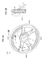
- the steering wheel 1 which has been subjected to the liquid pressure transfer printing will be described with reference to Figs. 2A and 2B by way of example.
- the steering wheel 1 includes a boss section 2 acting as a center of rotational movement of the steering wheel 1, spoke sections 3 arranged so as to radially extend from the boss section 2, and a rim section 4 connected to a distal end of each of the spoke sections 3 and formed to have a substantially annular shape.
- the rim section 4, as shown in Fig. 2A includes a long rim portion 41 of an elongated arcuate shape (positioned on an upper side in Fig. 2A), a short rim portion 42 of a short arcuate shape (positioned on a lower side in Fig.
- the long rim portion 41 and short rim portion 42 have a suitable transfer pattern P such as a woodgrain pattern, a straight grain pattern or the like applied thereto and are formed thereon with a topcoat.
- the grip sections 43 each have the end or ends of a corresponding one or two of the spoke sections 3 which extend from the boss section 2 connected thereto.
- the steering wheel 1A is immersed in a transfer liquid and subjected to liquid pressure transfer printing therein while being rotated.
- the spoke sections 3 are arranged close to the grip portions 43, to thereby cause force which is different from that acting on other portions such as the long rim portion 41, short rim portion 42 and the like to act on a transfer film F during the transfer, resulting in that liquid pressure transfer printing like that carried out on other portions cannot be attained on the grip portions 43.
- a suitable material such as leather or the like around the grip portions 43 may be employed after transfer printing, to thereby hide printing applied to the grip portions 43 or apply a special decoration effect, a gripping feeling or the like to the grip portions 43.
- a transfer pattern applied to the long rim portion 41 and short rim portion 42 by liquid pressure transfer printing is markedly decreased in distortion as compared with that obtained in the prior art.
- the transfer is carried out to substantially prevent occurrence of pattern distortion on a circumference of a section of the rim section 4 of the workpiece 1 which is taken in a thickness direction thereof perpendicular to the longitudinal direction thereof.
- Fig. 4 shows a check pattern formed on the long rim 41 or short rim 42 by liquid pressure transfer printing in accordance with an embodiment of the present invention, which is viewed in each of four directions around the circumference.
- Fig. 4 shows a check pattern formed on the long rim 41 or short rim 42 by liquid pressure transfer printing in accordance with an embodiment of the present invention, which is viewed in each of four directions around the circumference.
- the method in accordance with the described embodiment of the present invention substantially prevents distortion of the transfer pattern.
- the transfer pattern P is so formed that a joint line Pa of the transfer pattern P is positioned on a rear surface of the steering wheel 1 which is substantially invisible from a driver's seat when the steering wheel is mounted on a vehicle.
- the liquid pressure transfer printing apparatus 10 includes a transfer bath 11, a transfer film feed unit 12, and a workpiece holding and shifting unit 13.
- the transfer bath 11 has a transfer liquid L stored therein, which liquid is forcibly circulated at a reduced speed through a circulation pipeline 14 by means of a pump 15 as indicated at an arrow in Fig. 1 by way of example.
- the transfer bath 11 is provided on each of opposite side ends thereof with a guide chain 16 in a manner to extend between initial and terminal ends of the transfer bath 11 opposite to each other.
- the transfer bath 11 has a fan unit 17 arranged above the initial end thereof.
- Circulation of the transfer liquid L, the guide chains 16, the fan unit 17 and the like cooperate with each other to permit a transfer film F supported on a surface of the liquid L while being floated thereon to be stably conveyed toward the workpiece W or steering wheel 1A without causing ruffling or waving of the transfer liquid L.
- the illustrated embodiment as described above, is so constructed that the transfer film F is conveyed toward the workpiece W or steering wheel 1A.
- the illustrated embodiment is not limited to such construction.
- the steering wheel 1A could be moved toward the transfer film F kept stationary on the surface of the transfer liquid L in the transfer bath 11.
- both steering wheel 1A and transfer film F may be moved together. In the illustrated embodiment, it is merely required that both are approached to each other.
- the term "relative movement direction" defined herein in connection with a direction of movement or conveyance of the transfer film F covers all of the above-described approaching manners.
- upstream side in the relative movement direction indicates a side on which a transfer film F which has not yet been used for transfer printing is fed with respect to the workpiece W. Thus, it is substantially opposite to a side on which the joint line Pa is formed.
- the transfer film feed unit 12 includes a film roll 18 formed by winding the water-soluble transfer film F in a roll-like manner and a solvent tank 19 in which an activator S for providing a dry transfer ink printed on a carrier sheet with stickiness to render it transferable is stored. Such a treatment with the activator S is referred to as "activation" herein.
- the transfer film feed unit 12 also includes feed rollers 20. Such construction permits the transfer film F delivered from the film roll 18 to be activated by the activator S in the solvent tank 19 and then continuously fed to the transfer bath 11.
- the activator S is made by mixing a resin material, a pigment, a solvent, a plasticizer and the like with each other at a suitable ratio by way of example. Simply, a solvent such as a thinner or the like may be used for this purpose.
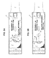
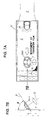
- the workpiece holding and shifting unit 13 is constructed so as to immerse the steering wheel 1A in the transfer liquid L while holding it thereon and then rotate the steering wheel 1A to shift it in the longitudinal direction of the steering wheel 1A or workpiece W. Immersion of the workpiece W or steering wheel 1A in the transfer liquid L by the workpiece holding and shifting unit 13 is carried out so that a deflection angle ⁇ defined between the loop surface R of the steering wheel 1A and the relative movement direction of the transfer film F may be suitably set to be within a range of ⁇ 90° with respect to the relative movement direction as shown in Fig.
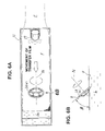
- an immersion attitude angle ⁇ of the loop surface R relative to the surface of the transfer liquid L may be suitably set to be within a range of ⁇ 80° with respect to an upright position of the workpiece as shown in Figs. 6A and 6B.
- the symbols "+” and “-" referred to in connection with the deflection angle or immersion attitude angle herein do not have any specific definition. Thus, they merely mean that when any one of rotational directions of the workpiece from a certain reference position is indicated by "+”, the other rotational direction is indicated by "-”.
- the steering wheel 1A is immersed in the transfer liquid L while being kept substantially erect or upright with respect to the surface of the transfer liquid L or keeping the immersion attitude angle ⁇ at substantially 90 degrees, wherein the deflection angle ⁇ is set to be about 65 degrees in Fig. 5A and about 90 degrees in Fig. 5B.
- the immersion attitude angle ⁇ is set to be about 50 degrees, therefore, the workpiece W or steering wheel 1A is immersed in the liquid while being inclined at an angle of about 40 degrees from an upright position thereof.
- a normal direction N of the loop surface R as viewed in plan is substantially conformed to the relative movement direction of the transfer film F, resulting in the deflection angle ⁇ being about 90 degrees.
- the immersion attitude angle ⁇ is set to be about 55 degrees, resulting in the steering wheel 1A being inclined at an angle of about 35 degrees from an erect position thereof.
- the normal direction N of the loop surface R as viewed in plan is rendered substantially perpendicular to the relative movement direction of the transfer film F, resulting in the deflection angle ⁇ being about 0 degree.
- the steering wheel 1A is shown as if it is vertically downwardly immersed in the transfer liquid. Alternatively, the steering wheel 1A may be obliquely lowered by means of a conveyor of an inverted triangular shape, an articulated robot or the like.
- the transfer film F is fed to the transfer bath 11 after it is coated thereon with the activator S. Alternatively, the transfer film F may be fed to the transfer bath 11 and then have a solvent or the like applied thereto for activation thereof. Further, in Fig. 1, the film F is continuously fed to the transfer bath 11 in which the transfer liquid L is circulated. Alternatively, individual transfer films F may be manually fed one by one to the transfer bath 11 in which the transfer liquid L is kept stationary so that they may be floated on the transfer liquid L.
- liquid pressure transfer printing carried out on the loop-like workpiece will be described in relation to operation of the liquid pressure transfer printing apparatus 10 constructed as described above.
- the transfer film F delivered from the film roll 18, as shown in Fig. 1, is coated on the surface thereof having the transfer ink deposited thereon with the activator S and then fed onto the transfer liquid L in the transfer bath 11.
- the transfer film F thus coated thereon with the activator S absorbs water, to thereby be softened and swollen, resulting in it being somewhat expanded in all directions.
- Coating of the activator on the transfer film F is carried out for the reason that the transfer film F is required to be normally kept dry because it is stored in the form of the film roll.
- the coating permits the ink coated surface of the transfer film F to be provided with stickiness.
- coating of the activator S on the transfer film F may be carried out after feeding of the transfer film F onto the transfer liquid L as well.
- the workpiece W or steering wheel 1A is initially immersed in the transfer liquid while being so set that a front surface thereof defined at the time when it is mounted on a vehicle is kept facing the transfer film F in the direction to which the transfer film F approaches, relatively, the steering wheel.
- immersion of the steering wheel 1A in the transfer liquid L is carried out while keeping the deflection angle and immersion attitude angle suitably set depending on conditions such as a size of the transfer pattern, a size of the steering wheel, a thickness of the steering wheel and the like.
- the initial immersion is started at the transfer not-required portion such as the grip portions 43 or the like.
- the parts may be covered with a masking material or the like to prevent the undesired transfer.
- the steering wheel 1A as shown in Figs. 3A and 3B by way of example, has the rim section 4 apparently cut crosswise by the surface of the transfer liquid L.
- the rim section 4 has a whole circumference of a section thereof which is taken substantially in a thickness direction thereof substantially concurrently contacted with the transfer film F.
- the workpiece holding and shifting unit 13 rotates the steering wheel 1A at a low speed to continuously immerse the steering wheel A in the transfer liquid L in the longitudinal direction thereof, resulting in the steering wheel gradually being subjected to liquid pressure transfer printing.
- Immersion of the steering wheel 1A in the transfer liquid L is carried out at two sites thereof.
- the liquid pressure transfer printing is carried out at one of the immersion sites or a site of the steering wheel which is immersed in the surface of the transfer liquid L on the upstream side in the relative movement direction of the transfer film F or at a site thereof which is initially contacted with the transfer film F.
- the site is referred to as a transfer initiating site Z herein.
- the transfer film F is gradually downwardly drawn into the transfer liquid with rotation of the steering wheel 1A to generate a liquid pressure, which acts to subject the steering wheel to liquid pressure transfer printing.
- the rim section 4 is gradually drawn out of the surface of the transfer liquid L, to thereby fail to generate the liquid pressure, resulting in the steering wheel being kept from printing.
- it is required to constantly replenish a circumference of the rim section 4 with a portion of the transfer film F which has not yet been used for transfer printing, so that a relative transfer speed of the transfer film F and a rotational speed of the steering wheel 1A are set to be substantially equal to each other.
- the method described is carried out to constantly feed a portion of the transfer film F which has not yet been used for transfer printing to the circumference of the section of the rim section 4 defined in the thickness direction thereof, to thereby remarkably restrain distortion of the transfer pattern as compared with the prior art.
- the rim section 4 substantially escapes from distortion of the transfer pattern applied thereto as viewed in all directions around the circumference of the rim section 4.
- suitable setting of the deflection angle and immersion attitude angle permits the joint line Pa of the transfer pattern P to be positioned on the rear surface of the steering wheel which is substantially invisible from a driver's seat when the steering wheel is mounted on a vehicle, as shown in Figs. 2B and 3B by way of example, resulting in the joint line Pa being substantially inconspicuous.
- the steering wheel 1A After termination of rotation of the steering wheel 1A, the steering wheel 1A is removed from the surface of the transfer liquid L, resulting in the liquid pressure transfer printing being substantially completed.
- the steering wheel 1A which has been thus subjected to the liquid pressure transfer printing has a residue of the transfer film F which has not been dissolved in the transfer liquid L adhered thereto.
- the steering wheel 1A is subjected to washing by showering or the like, followed by drying.
- the steering wheel 1A having the transfer pattern P thus printed thereon provides a decorated product in accordance with one aspect of the present invention.
- a portion of the steering wheel which has been subjected to the liquid pressure transfer printing exhibits increased gloss and depth
- it is formed thereon with a transparent topcoat by spraying or the like.
- the topcoat thus formed may be subjected to polishing by buffing or the like.
- a transfer pattern to the workpiece W such as the steering wheel 1A or the like is carried out so as to minimize distortion of the pattern on the circumference of the section of the workpiece taken in the thickness direction thereof.
- the transfer pattern actually obtained is extensively varied due to complicated entangling of a variety of factors including an attitude of the steering wheel 1A (setting of the deflection angle and immersion attitude angle), a feed rate of the transfer film F (relative transfer speed), a size of the workpiece W, a sectional configuration of the workpiece W, viscosity of the activated transfer film F, and the like.
- a satisfactory transfer pattern may be obtained when the immersion attitude angle ⁇ between the loop surface R and the surface of the transfer liquid L is set to be within a range between -20° and -10° or an angle of the workpiece defined on the basis of an upright position thereof is set to be within a range between -80° and -70° and a normal direction N of the loop surface R as viewed in plan is inclined by an angle of from 10° to 20° or the deflection angle is set to be within a range between 70° and 80°.
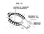
- the joint line Pa of the transfer pattern P formed on the rear surface of the steering wheel 1A is so formed that the transfer film F fed from the upstream side is divided into two parts in a lateral direction thereof by the steering wheel 1A, which parts then lap on inner and outer lateral sides of the steering wheel 1A to the rear side thereof and then are joined to each other in order while being contacted with each other (Fig. 10).
- misregistration causes misregistration of the transfer pattern at the joint line Pa, as well as a difference in elongation of the transfer film F, resulting in a difference in gradation being often notedly observed at the joint line Pa.
- liquid pressure transfer which reduces a difference in gradation at the joint line Pa is considered to be satisfactory.
- the immersion attitude angle ⁇ is set to be within a range between -20° and -10° or an angle of the workpiece defined on the basis of an upright position thereof is set to be within a range between -80° and-70°.
- the pattern transferred to the surface of the rim section 4 is substantially shifted in a peripheral direction thereof.
- an experiment by the inventor revealed that laying-down of the steering wheel 1A reduces shifting of the pattern in the peripheral direction of the rim section 4.
- transfer of the transfer film F to the workpiece W while keeping it lying on the transfer liquid permits a locus of lapping of the transfer film F on the workpiece W to substantially coincide with the circumference of the section of the workpiece W taken in the thickness direction thereof, to thereby minimize shifting or misregistration of the pattern in the circumferential direction of the rim section 4.
- the immersion attitude angle and a feed rate of each of the transfer film F and workpiece W are set so as to permit the locus of the lapping of the transfer film on the workpiece W to substantially coincide with the circumference of the section of the workpiece in the thickness direction thereof.
- a line substantially normal to a direction of movement of the transfer film F which is designated by F1 is defined so as to substantially conform to the circumference of the section of the workpiece W in the thickness direction thereof which is indicated by two-dot chain lines Pt.
- the outer peripheral side of the steering wheel 1A is increased in immersion speed as compared with the inner peripheral side thereof because the former has a diameter larger than the latter.
- the pattern is apt to elongate or enlarge on the outer peripheral side as compared with the inner peripheral side.
- the pattern tends to elongate on the downstream side of the steering wheel 1A as compared with the upstream side thereof, because of lapping of the transfer film F on the steering wheel on the downstream side (see Fig. 10).
- the normal direction N of the loop surface R as viewed in plan is set to be inclined by an angle of 10 to 20 degrees with respect to the relative movement direction of the transfer film F or the deflection angle is set to be 70 to 80 degrees.
- Such arrangement permits the outer peripheral side of the workpiece W on which elongation of the pattern easily occurs to be positioned on the upstream side on which the pattern elongation is hard to occur and the inner peripheral side of the workpiece W on which the pattern elongation is hard to occur to be positioned on the downstream side which causes the pattern elongation to be readily occur, resulting in such factors contrary to each other being offset by each other.
- the above-described fact permits a distance or time by which the transfer film F laps on the outer lateral side of the workpiece W to the bottom side thereof to be substantially equal to that by which it laps on the inner lateral side to the bottom side, resulting in the pattern elongation on the outer side of the workpiece W and that on the inner side substantially coinciding with each other, so that a difference in gradation at the joint line Pa may be substantially eliminated.
- the joint line Pa is positionally varied depending on an attitude of the workpiece W, a feed rate of the transfer film F, a size of the workpiece W, a configuration of the workpiece W, viscosity of the transfer film F activated and the like. This often causes a distance by which the transfer film F laps on the outer lateral side of the workpiece W to the bottom side thereof and that by which it laps on the inner lateral side to the bottom side not to coincide with each other.
- the illustrated embodiment wherein the steering wheel 1A is applied as the workpiece W permits the joint line Pa to be formed at a position on the workpiece W which is shifted somewhat toward a center of the workpiece W. This would be due to the fact that immersion of the workpiece W is carried out toward the center as viewed in plan and the transfer film F is increased in viscosity.
- the steering wheel may be applied as the loop-like workpiece by way of example substantially restrains distortion of a transfer pattern over the whole circumference of the rim section of the steering wheel taken in the thickness direction thereof as compared with the prior art, to thereby permit transfer of the transfer pattern to the steering wheel to be carried out substantially in conformity to the circumference of the rim section.
- the present invention at least preferably permits a distance by which the transfer film F divided into two parts laps on the inner lateral side of the steering wheel to the lower side thereof and that by which it laps on the outer lateral side to the lower side to be substantially equal to each other, to thereby render elongation of one of the two parts of the transfer film and that of the other part substantially equal to each other, so that transfer of the pattern on the transfer film to the steering wheel may be attained while substantially eliminating a difference in gradation at the joint line.
- the present invention permits the joint line of the transfer pattern to be positioned on the rear surface of the steering wheel which is substantially invisible from a driver's seat when the steering wheel is mounted on a vehicle, resulting in the transfer pattern such as a straight grain pattern, a carbon pattern or the like being increased in aesthetic characteristics.
- the present invention permits the deflection angle and immersion attitude angle to be optimumly set depending on a size of each of the transfer pattern and workpiece, a configuration thereof and the like.
- the present invention may be effectively applied to any loop-like article such as a hula hoop, rings in gymnastics, a towel ring, a chair back and the like in addition to the steering wheel.
Landscapes
- Engineering & Computer Science (AREA)
- Mechanical Engineering (AREA)
- Health & Medical Sciences (AREA)
- General Health & Medical Sciences (AREA)
- Textile Engineering (AREA)
- Vascular Medicine (AREA)
- Decoration By Transfer Pictures (AREA)
- Printing Methods (AREA)
- Steering Controls (AREA)
Applications Claiming Priority (2)
| Application Number | Priority Date | Filing Date | Title |
|---|---|---|---|
| JP17335899 | 1999-06-18 | ||
| JP17335899 | 1999-06-18 |
Publications (3)
| Publication Number | Publication Date |
|---|---|
| EP1060902A2 true EP1060902A2 (fr) | 2000-12-20 |
| EP1060902A3 EP1060902A3 (fr) | 2001-03-07 |
| EP1060902B1 EP1060902B1 (fr) | 2003-09-10 |
Family
ID=15958937
Family Applications (1)
| Application Number | Title | Priority Date | Filing Date |
|---|---|---|---|
| EP00305158A Expired - Lifetime EP1060902B1 (fr) | 1999-06-18 | 2000-06-19 | Procédé de transfert par pression de liquide pour des objets annulaires et produits ainsi décorés |
Country Status (8)
| Country | Link |
|---|---|
| US (1) | US6939585B1 (fr) |
| EP (1) | EP1060902B1 (fr) |
| JP (1) | JP3388404B2 (fr) |
| KR (1) | KR100477159B1 (fr) |
| CN (1) | CN100347003C (fr) |
| DE (1) | DE60005088T2 (fr) |
| ES (1) | ES2206142T3 (fr) |
| TW (1) | TW503189B (fr) |
Cited By (4)
| Publication number | Priority date | Publication date | Assignee | Title |
|---|---|---|---|---|
| FR2791606A1 (fr) * | 1999-04-02 | 2000-10-06 | Youn Soo Cho | Procede de transcription de marques sur la jante d'un volant de direction d'une automobile moyennant l'utilisation d'une pression d'eau |
| FR2965751A1 (fr) * | 2010-10-12 | 2012-04-13 | Jean Noel Claveau | Procede et equipement de decoration d’un article |
| CN102596586A (zh) * | 2009-10-28 | 2012-07-18 | 株式会社Taica | 液面残留膜的回收方法和应用该回收方法的液压转印方法、及其回收装置和应用该回收装置的液压转印装置 |
| WO2020143821A1 (fr) * | 2019-01-11 | 2020-07-16 | 深圳凯和科技有限公司 | Procédé d'impression par transfert thermique pour une adhérence de film précise |
Families Citing this family (8)
| Publication number | Priority date | Publication date | Assignee | Title |
|---|---|---|---|---|
| KR100359130B1 (ko) * | 2000-08-11 | 2002-11-04 | 조윤수 | 자동차용 스티어링휠림의 수압전사방법 |
| WO2005077676A1 (fr) * | 2004-02-18 | 2005-08-25 | Taica Corporation | Produit de transfert hydraulique |
| US8360239B2 (en) | 2010-02-15 | 2013-01-29 | Kroell Keith B | Kit for transferring an image onto an object |
| JP5049380B2 (ja) * | 2010-12-10 | 2012-10-17 | 株式会社タイカ | 意匠面浄化機構を具えた液圧転写方法並びにその液圧転写装置 |
| JP5027348B1 (ja) * | 2011-12-08 | 2012-09-19 | 株式会社タイカ | 転写フィルムの液面活性化方法並びにこれを適用した液圧転写方法並びに液圧転写装置 |
| US9878344B2 (en) * | 2016-04-21 | 2018-01-30 | Yung Hung Precision Machinery Co., Ltd. | Coating machine for hydrographics |
| CN107175943B (zh) * | 2017-07-18 | 2019-11-08 | 深圳凯和科技有限公司 | 热转印方法及系统 |
| CN111591025B (zh) * | 2020-05-28 | 2021-12-21 | 韦邦兰 | 一种拖鞋印花装置 |
Family Cites Families (7)
| Publication number | Priority date | Publication date | Assignee | Title |
|---|---|---|---|---|
| US4229239A (en) | 1977-07-27 | 1980-10-21 | Dai Nippon Insatsu Kabushiki Kaisha | Transfer printing method |
| JPS615981A (ja) | 1984-06-20 | 1986-01-11 | Molten Corp | ステアリングホイ−ルの木目模様印刷方法 |
| JPH09254598A (ja) * | 1996-03-19 | 1997-09-30 | Koito Mfg Co Ltd | 車両灯具用化粧部材の印刷方法および車両灯具用化粧部材 |
| JP3368457B2 (ja) * | 1997-04-25 | 2003-01-20 | 株式会社キュービック | 液圧転写印刷方法 |
| JP3890454B2 (ja) * | 1997-06-03 | 2007-03-07 | 株式会社キュービック | 液圧転写印刷が施されたステアリングホイールの製造方法 |
| TW415898B (en) * | 1998-05-14 | 2000-12-21 | Cho Youn Soo | Method for manufacturing the rim of a steering wheel for vehicles |
| KR100275548B1 (ko) * | 1998-05-14 | 2000-12-15 | 조윤수 | 수압전사방법 |
-
2000
- 2000-06-06 JP JP2000169325A patent/JP3388404B2/ja not_active Expired - Lifetime
- 2000-06-16 TW TW089111801A patent/TW503189B/zh not_active IP Right Cessation
- 2000-06-16 US US09/594,794 patent/US6939585B1/en not_active Expired - Lifetime
- 2000-06-17 CN CNB001226606A patent/CN100347003C/zh not_active Expired - Lifetime
- 2000-06-19 KR KR10-2000-0033675A patent/KR100477159B1/ko not_active Expired - Fee Related
- 2000-06-19 EP EP00305158A patent/EP1060902B1/fr not_active Expired - Lifetime
- 2000-06-19 ES ES00305158T patent/ES2206142T3/es not_active Expired - Lifetime
- 2000-06-19 DE DE60005088T patent/DE60005088T2/de not_active Expired - Fee Related
Cited By (6)
| Publication number | Priority date | Publication date | Assignee | Title |
|---|---|---|---|---|
| FR2791606A1 (fr) * | 1999-04-02 | 2000-10-06 | Youn Soo Cho | Procede de transcription de marques sur la jante d'un volant de direction d'une automobile moyennant l'utilisation d'une pression d'eau |
| US6461466B1 (en) | 1999-04-02 | 2002-10-08 | Cho Youn-Soo | Transcribing method of steering wheel rim of automobile using water pressure |
| CN102596586A (zh) * | 2009-10-28 | 2012-07-18 | 株式会社Taica | 液面残留膜的回收方法和应用该回收方法的液压转印方法、及其回收装置和应用该回收装置的液压转印装置 |
| CN102596586B (zh) * | 2009-10-28 | 2014-07-16 | 株式会社Taica | 液面残留膜的回收方法和应用该回收方法的液压转印方法、及其回收装置和应用该回收装置的液压转印装置 |
| FR2965751A1 (fr) * | 2010-10-12 | 2012-04-13 | Jean Noel Claveau | Procede et equipement de decoration d’un article |
| WO2020143821A1 (fr) * | 2019-01-11 | 2020-07-16 | 深圳凯和科技有限公司 | Procédé d'impression par transfert thermique pour une adhérence de film précise |
Also Published As
| Publication number | Publication date |
|---|---|
| TW503189B (en) | 2002-09-21 |
| ES2206142T3 (es) | 2004-05-16 |
| DE60005088T2 (de) | 2004-07-15 |
| JP2001058497A (ja) | 2001-03-06 |
| EP1060902B1 (fr) | 2003-09-10 |
| CN1280902A (zh) | 2001-01-24 |
| KR100477159B1 (ko) | 2005-03-18 |
| DE60005088D1 (de) | 2003-10-16 |
| KR20010049575A (ko) | 2001-06-15 |
| JP3388404B2 (ja) | 2003-03-24 |
| US6939585B1 (en) | 2005-09-06 |
| CN100347003C (zh) | 2007-11-07 |
| EP1060902A3 (fr) | 2001-03-07 |
Similar Documents
| Publication | Publication Date | Title |
|---|---|---|
| EP1088676B1 (fr) | Procédé de transfert par pression de liquide pour des objets annulaires et produits ainsi décorés | |
| EP1060902B1 (fr) | Procédé de transfert par pression de liquide pour des objets annulaires et produits ainsi décorés | |
| JP3890454B2 (ja) | 液圧転写印刷が施されたステアリングホイールの製造方法 | |
| US6235227B1 (en) | Process of manufacturing a steering wheel | |
| CN1478002A (zh) | 用于制造一种设有装饰层的金属罐的方法、装置和系统 | |
| KR100431967B1 (ko) | 지그 조립체 및 이를 사용한 수압전사방법 | |
| JP3954274B2 (ja) | ステアリングホイールの水圧転写方法 | |
| KR100408551B1 (ko) | 수압전사를 이용한 자동차용 스티어링휠 림의 제조방법 및 이에 의해 제조된 자동차용 스티어링휠 림 | |
| JPH0455380B2 (fr) | ||
| JPH1133481A (ja) | スエード調の外観を有する装飾材及びその製造方法 | |
| JPH0148847B2 (fr) | ||
| KR20040016517A (ko) | 자동차용 스티어링휠 림의 수압전사방법 및 이에 의해제조된 자동차용 스티어링휠 | |
| JP2002536257A (ja) | 接着剤無しの前縁を備えたラベルを容器に巻き付ける方法及び装置 | |
| JPH0640004A (ja) | 丸パイプ加飾装置 | |
| JP2004160820A (ja) | 自動車部品の転写方法と自動車部品の転写装置 | |
| JPH03272996A (ja) | デザインハンドレールの製造方法 | |
| JPH0455120B2 (fr) | ||
| JP2005075011A (ja) | 車両用サンバイザ | |
| JPS5870757A (ja) | 植毛層を有する成形玉縁の製造法 | |
| WO2001036111A3 (fr) | Procede de realisation d'un materiau support en forme de film, recouvert d'un adhesif | |
| JPH07276898A (ja) | 異形凹凸表面を有する加飾施工品並びにその製造方法 | |
| JPH03275331A (ja) | 車両用内装材の端末処理方法 |
Legal Events
| Date | Code | Title | Description |
|---|---|---|---|
| PUAI | Public reference made under article 153(3) epc to a published international application that has entered the european phase |
Free format text: ORIGINAL CODE: 0009012 |
|
| AK | Designated contracting states |
Kind code of ref document: A2 Designated state(s): DE ES FR GB IT SE |
|
| AX | Request for extension of the european patent |
Free format text: AL;LT;LV;MK;RO;SI |
|
| PUAL | Search report despatched |
Free format text: ORIGINAL CODE: 0009013 |
|
| AK | Designated contracting states |
Kind code of ref document: A3 Designated state(s): AT BE CH CY DE DK ES FI FR GB GR IE IT LI LU MC NL PT SE |
|
| AX | Request for extension of the european patent |
Free format text: AL;LT;LV;MK;RO;SI |
|
| RIC1 | Information provided on ipc code assigned before grant |
Free format text: 7B 41M 5/025 A, 7B 44C 1/175 B, 7B 62D 1/06 B |
|
| 17P | Request for examination filed |
Effective date: 20010821 |
|
| AKX | Designation fees paid |
Free format text: DE ES FR GB IT SE |
|
| 17Q | First examination report despatched |
Effective date: 20011214 |
|
| GRAH | Despatch of communication of intention to grant a patent |
Free format text: ORIGINAL CODE: EPIDOS IGRA |
|
| GRAS | Grant fee paid |
Free format text: ORIGINAL CODE: EPIDOSNIGR3 |
|
| GRAA | (expected) grant |
Free format text: ORIGINAL CODE: 0009210 |
|
| RIN1 | Information on inventor provided before grant (corrected) |
Inventor name: MIZUTA, YOSHIHITO |
|
| AK | Designated contracting states |
Kind code of ref document: B1 Designated state(s): DE ES FR GB IT SE |
|
| REG | Reference to a national code |
Ref country code: GB Ref legal event code: FG4D |
|
| REF | Corresponds to: |
Ref document number: 60005088 Country of ref document: DE Date of ref document: 20031016 Kind code of ref document: P |
|
| REG | Reference to a national code |
Ref country code: SE Ref legal event code: TRGR |
|
| REG | Reference to a national code |
Ref country code: ES Ref legal event code: FG2A Ref document number: 2206142 Country of ref document: ES Kind code of ref document: T3 |
|
| ET | Fr: translation filed | ||
| PLBE | No opposition filed within time limit |
Free format text: ORIGINAL CODE: 0009261 |
|
| STAA | Information on the status of an ep patent application or granted ep patent |
Free format text: STATUS: NO OPPOSITION FILED WITHIN TIME LIMIT |
|
| 26N | No opposition filed |
Effective date: 20040614 |
|
| PGFP | Annual fee paid to national office [announced via postgrant information from national office to epo] |
Ref country code: DE Payment date: 20080626 Year of fee payment: 9 Ref country code: ES Payment date: 20080717 Year of fee payment: 9 |
|
| PGFP | Annual fee paid to national office [announced via postgrant information from national office to epo] |
Ref country code: GB Payment date: 20080625 Year of fee payment: 9 |
|
| PGFP | Annual fee paid to national office [announced via postgrant information from national office to epo] |
Ref country code: SE Payment date: 20080630 Year of fee payment: 9 |
|
| GBPC | Gb: european patent ceased through non-payment of renewal fee |
Effective date: 20090619 |
|
| PG25 | Lapsed in a contracting state [announced via postgrant information from national office to epo] |
Ref country code: GB Free format text: LAPSE BECAUSE OF NON-PAYMENT OF DUE FEES Effective date: 20090619 |
|
| PG25 | Lapsed in a contracting state [announced via postgrant information from national office to epo] |
Ref country code: DE Free format text: LAPSE BECAUSE OF NON-PAYMENT OF DUE FEES Effective date: 20100101 |
|
| REG | Reference to a national code |
Ref country code: ES Ref legal event code: FD2A Effective date: 20090620 |
|
| PG25 | Lapsed in a contracting state [announced via postgrant information from national office to epo] |
Ref country code: ES Free format text: LAPSE BECAUSE OF NON-PAYMENT OF DUE FEES Effective date: 20090620 |
|
| PG25 | Lapsed in a contracting state [announced via postgrant information from national office to epo] |
Ref country code: SE Free format text: LAPSE BECAUSE OF NON-PAYMENT OF DUE FEES Effective date: 20090620 |
|
| PGFP | Annual fee paid to national office [announced via postgrant information from national office to epo] |
Ref country code: FR Payment date: 20111115 Year of fee payment: 12 |
|
| REG | Reference to a national code |
Ref country code: FR Ref legal event code: ST Effective date: 20130228 |
|
| PG25 | Lapsed in a contracting state [announced via postgrant information from national office to epo] |
Ref country code: FR Free format text: LAPSE BECAUSE OF NON-PAYMENT OF DUE FEES Effective date: 20120702 |
|
| PGFP | Annual fee paid to national office [announced via postgrant information from national office to epo] |
Ref country code: IT Payment date: 20160628 Year of fee payment: 17 |
|
| PG25 | Lapsed in a contracting state [announced via postgrant information from national office to epo] |
Ref country code: IT Free format text: LAPSE BECAUSE OF NON-PAYMENT OF DUE FEES Effective date: 20170619 |