EP1060830A1 - Vorrichtung und Verfahren zur thermographischen Untersuchung von Funktionsflächen an Umformwerkzeugen - Google Patents
Vorrichtung und Verfahren zur thermographischen Untersuchung von Funktionsflächen an Umformwerkzeugen Download PDFInfo
- Publication number
- EP1060830A1 EP1060830A1 EP00111869A EP00111869A EP1060830A1 EP 1060830 A1 EP1060830 A1 EP 1060830A1 EP 00111869 A EP00111869 A EP 00111869A EP 00111869 A EP00111869 A EP 00111869A EP 1060830 A1 EP1060830 A1 EP 1060830A1
- Authority
- EP
- European Patent Office
- Prior art keywords
- window
- cover
- channel
- temperature measuring
- heat radiation
- Prior art date
- Legal status (The legal status is an assumption and is not a legal conclusion. Google has not performed a legal analysis and makes no representation as to the accuracy of the status listed.)
- Withdrawn
Links
Images

Classifications
-
- B—PERFORMING OPERATIONS; TRANSPORTING
- B23—MACHINE TOOLS; METAL-WORKING NOT OTHERWISE PROVIDED FOR
- B23Q—DETAILS, COMPONENTS, OR ACCESSORIES FOR MACHINE TOOLS, e.g. ARRANGEMENTS FOR COPYING OR CONTROLLING; MACHINE TOOLS IN GENERAL CHARACTERISED BY THE CONSTRUCTION OF PARTICULAR DETAILS OR COMPONENTS; COMBINATIONS OR ASSOCIATIONS OF METAL-WORKING MACHINES, NOT DIRECTED TO A PARTICULAR RESULT
- B23Q17/00—Arrangements for observing, indicating or measuring on machine tools
- B23Q17/09—Arrangements for observing, indicating or measuring on machine tools for indicating or measuring cutting pressure or for determining cutting-tool condition, e.g. cutting ability, load on tool
- B23Q17/0904—Arrangements for observing, indicating or measuring on machine tools for indicating or measuring cutting pressure or for determining cutting-tool condition, e.g. cutting ability, load on tool before or after machining
-
- B—PERFORMING OPERATIONS; TRANSPORTING
- B23—MACHINE TOOLS; METAL-WORKING NOT OTHERWISE PROVIDED FOR
- B23Q—DETAILS, COMPONENTS, OR ACCESSORIES FOR MACHINE TOOLS, e.g. ARRANGEMENTS FOR COPYING OR CONTROLLING; MACHINE TOOLS IN GENERAL CHARACTERISED BY THE CONSTRUCTION OF PARTICULAR DETAILS OR COMPONENTS; COMBINATIONS OR ASSOCIATIONS OF METAL-WORKING MACHINES, NOT DIRECTED TO A PARTICULAR RESULT
- B23Q17/00—Arrangements for observing, indicating or measuring on machine tools
- B23Q17/09—Arrangements for observing, indicating or measuring on machine tools for indicating or measuring cutting pressure or for determining cutting-tool condition, e.g. cutting ability, load on tool
Definitions
- the invention relates to a device and a method for quick and simple thermographic examination of functional surfaces on forming tools according to Preamble of claims 1 and 11.
- [1] is used to determine the temperature of the wear surface of a forming or cutting tool proposed one (or more) thin film sensors to integrate into a functional or wear protection layer of the tool. This requires a lot of effort and high costs. Also enable thin film sensors just a selective temperature measurement. The determination of the temperature distribution would only be possible with a large number of sensors and would do even more Require effort and cost. Furthermore, with the integration of a thin film sensor to achieve high measuring dynamics in a tool.
- the object of the present invention is therefore to provide a device for quick and easy thermographic examination of functional areas Specify forming tools in situ, which is used to determine the temperature distribution without obstructing the work process with the objective of optimization the wear and forming behavior of the tools used enables to increase without effort and costs as well as a procedure with the same To develop advantages.
- the invention is related to the device to be created by the features of Claim 1 reproduced.
- the further claims contain advantageous refinements and developments of the device according to the invention (claims 2 to 9) and the process to be created (claim 11).
- Beneficial Further developments of the method according to the invention are contained in patent claims 12 to 15.
- the basic principle of the device according to the invention is that the thermographic Examination of the functional surface from the inside of the tool the channel or channels introduced. This is the first time the disability and instantaneous measurement of absolute temperatures and two-dimensional Temperature distributions of the workpiece surface directly in the contact area tool-workpiece enables in situ. This enables the forming process itself to be examined and are optimized in terms of machining parameters, tool geometry and of the tribological system (tool material, tool coating, lubricant, surface topography). The measurement can not only be carried out in trial operation are used, but also in series production for dynamic process control become.
- the effort and the cost of the device according to the invention are compared to those low for attaching a measuring field from a variety of thin-film sensors.
- a measuring field would only be an approximate determination of the Allow spatial temperature distribution because the thin-film sensors only selectively measure up.
- Each channel opening on the workpiece side is covered with a window and on the window a coating is applied.
- the device according to the invention attached a cover over the window or instead of the window, which made a tool material commonly used in forming processes, for example a tool steel containing chrome.
- the advantage of this embodiment is that it is simple, quick and inexpensive Interchangeability of the cover and thus the tool material and the Tool surfaces.
- a coating is applied to the cover.
- the advantage of this embodiment is that the cover is easily replaceable is coated and independent of the rest of the tool or the measuring device can be. This leads to time and cost savings and enables immediately comparative measurements with a basic device. By means of comparative Measurements can be iteratively carried out in optimization loops in an optimally customized manner Coating can be developed for every application in metal forming.
- a cover can be made - usually from a forming process Tool steel used - with interesting for the forming technology Coat materials much better and more firmly than most others Surfaces that withstand the loads during a forming process, for example, a diamond surface, due to the covalent nature of the bond insufficient liability is achieved. Adequate liability is however a prerequisite for temperature measurements over longer periods during the Forming process without the coating flaking off. this makes possible Service life tests of the forming device with parallel temperature measurement.
- the window under the cover supports it flatly and thus prevents it deformation or breakage of a thinner cover due to the stress during the forming process.
- covers with Sufficient mechanical strength can be dispensed with the window become.
- the device in particular the temperature measuring device, is calibrated on the emission properties of the material or coating required.
- the calibration effort for different materials or tool coatings can, however, be reduced to a single calibration in which each a cover from a single one commonly used in forming processes Tool material placed on the channel above or instead of the window becomes.
- the material and the Thickness of the cover chosen such that the image of the temperature distribution of the Functional surface (or the underside of the coating), which by means of heat conduction is passed through the cover, in the transverse direction to this intended Imaging direction is not falsified beyond a defined limit.
- the temperature distribution In order to determine the influence of a specific cover, the temperature distribution must be can be measured with and without cover. This can be IR-transparent Coatings can be done easily. By examining covers different materials and thickness, both values can be optimized iteratively with regard to a minimal deviation of the measured and the actual Temperature distribution in the coating. Coverage optimized in this way can then can be used for the thermographic examination of any coating.
- the cover is attached by gluing.
- This fastening method allows a flat and therefore More uniform fastening than, for example, using screws or a clamp connection.
- the cover is subjected to loads, which can lead to internal tension if the fastening is not uniform and thereby the image of the temperature distribution transported by means of heat conduction can falsify the functional surface or the coating.
- screw heads or clamps can be due to the small thickness the cover can scarcely be sunk into it, increasing the possibilities for its arrangement be severely restricted, since they do not impair the forming process should.
- Suitable adhesives are, for example, commercially available two-component adhesives that are suitable for the heat radiation is permeable and the short-term temperature peaks of up to 500 degrees Celsius and continuous temperatures of up to 200 degrees Celsius without critical ones Survive impairment of liability.
- the window is off constructed of a material that has a similar thermal conductivity to that Cover. This prevents heat accumulation on the underside of the cover, that would distort the thermographic examination.
- a diamond or germanium window is particularly suitable. Their advantage is there in that these materials have a good permeability to heat radiation own and thus pass on the image of the temperature distribution well. On the other hand they have good thermal conductivity around the heat from the bottom of the Derive cover and avoid heat build-up.
- this device is in the channel at least one IR mirror arranged for forwarding the workpiece side in the Channel entering heat radiation in the direction of the temperature measuring device.
- IR mirrors enable the image to be forwarded the temperature distribution to the temperature measuring device.
- a light guide is arranged for the forwarding of those entering the channel on the workpiece side Heat radiation in the direction of the temperature measuring device. Even over one Optical fibers can map the temperature distribution through an odd channel be forwarded to the temperature measuring device.
- the temperature measuring device contains a thermal camera.
- Their advantage is that they are Examination of the temperature distribution in a simple and very fast way both at a selected point in time (single image) and at their Development over a long period of time (sequence of single images).
- this device contains additionally an evaluation unit to compensate for IR losses. Both that Windows and the mostly existing adhesive layer do not have 100 percent Permeability to heat radiation. This loss factor can be independent of the and then thermographic examination of the forming process can be determined during the investigation of the forming process (or afterwards) using the Evaluation unit can be compensated arithmetically. The same applies to others measurable and regular (not accidental) influencing parameters.
- a coating is applied to the window and then the channel is covered with covered the window.
- the Window or instead of the window attached a cover consisting of a Tool material usually used in forming processes.
- the Cover applied a coating.
- This process step is firstly that it is directly comparative Measurements of different coatings with a basic device enables. By means of comparative measurements, optimization loops can be iterative an optimally tailored coating for every application in metal forming be developed.
- thermographic studies on IR-transmissive layers each with and without heat loss [with and without window] or [with and without cover and window] or [with and without cover without window])
- a calibration curve is calculated on the basis of these test results, and that on the basis of this calibration curve during the thermographic examination of any ie IR-transparent or IR-opaque layers the heat losses ([with Window and without cover] or [with window and with cover] or [with Cover and without window]) can be compensated arithmetically.
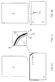
- FIG. 1 shows schematically and not to scale a device for thermographic Examination of functional surfaces on forming tools consisting of a tool 1 (here the drawing edge in the strip drawing test), which in Area of the functional surface 10 a extending through the tool 1 Channel 11 has.
- the workpiece-side opening of the channel 11 is with a window 12 occupied.
- the window 12 is fitted into the tool 1 (here: into the drawing edge) in such a way that that it is flush with the surface of the drawing edge and so a smooth support and Offers support surface for the metallic cover 14 fastened above.
- the attachment is carried out in the form of an adhesive layer 13 between cover 14 and Window 12 or top of the tool 1. On the cover 14 there is one investigating coating 15 applied.
- a hold-down device 2 is located above the drawing edge to see.
- FIG. 2 shows an IR swivel mirror 111 in the channel 11, which mirrors that of the Functional area 10 outgoing IR radiation to a temperature measuring device 3 leads to a thermal camera here.
- a Temperature measuring device 3 At this temperature measuring device 3 is a Evaluation unit 4 coupled - here a special measuring computer.
- the image of the Temperature distribution from the bottom of the coating 15 is by means of heat conduction passed through the cover 14 to the top of the adhesive layer 13, from there by means of heat radiation through the adhesive layer 13 and through the window 12 and then through the channel 11 (redirected by means of the IR mirror 111) to the temperature measuring device 3.
- the recorded by the temperature measuring device 3 (thermal camera) Image of the temperature distribution from the underside of the coating 15 is mathematically modified in the evaluation unit 4 such that on the way from the Coating 15 up to the temperature measuring unit 3 compensates for heat losses become.
- the swivel mirror 111 is moved via a mirror support 112 by a swivel device 113 pivoted. This allows the thermographic to be moved / shifted Image field over the workpiece-side channel opening and thus also the thermographic Examination of larger parts of the functional surface 10.
- the cover 14 is made of chromium Tool steel 160 CrMoV 12 (German material number: 1.2379), has a thickness of 300 ⁇ m and covers the entire drawing edge. Comparative forming tests with and without cover 14 there is a deviation of the gradient between the maximum value and average temperature distribution value of approximately 10 percent.
- the window 12 is made of CVD diamond and is rectangular with an edge length of 2 mm and a maximum thickness of 500 ⁇ m.
- the surface of the window is attached to the Tool geometry adjusted.
- the Production of the window with a radius that corresponds to that of the basic tool.
- the window is expediently installed in the tool by gluing into a precisely fitting recess in the tool, e.g. manufactured by spark erosion can be.
- the window lies "like a manhole cover" in the Tool.
- the cover 14 is on the window 12 and the surface of the tool 1 by means of an adhesive layer 13 made of commercially available, IR-permeable two-component adhesive attached.
- an adhesive layer 13 made of commercially available, IR-permeable two-component adhesive attached.
- a typical coating is 15 - titanium nitride 5 ⁇ m thick - examined thermographically in situ during forming: For this purpose, it is applied to the cover 14 using customary deposition methods and then the cover 14 is attached to the tool 1 - by means of the adhesive layer 13 - a pulling edge - fastened over the diamond window 12. Then the tool 1 used, i.e. A workpiece is formed over the drawing edge. As a result, forms a characteristic temperature distribution in the coating 15, which Statements about the load and the state of wear of the coating 15 are permitted. The image of this temperature distribution is generated by heat conduction through the cover 14 and by means of heat radiation through the adhesive layer 13, the diamond window 12 led to the thermal camera 3 via the mirror 111. That from the thermal camera 3 Recorded image of the temperature distribution is in the form of the evaluation unit 4 forwarded to a measuring computer, there are heat losses on the way from the coating 15 up to the thermal camera 3 occur, computationally compensated and carried out further evaluations.
- the device according to the invention and the method according to the invention prove to be effective as special in the embodiments of the example described above suitable for the quick and easy thermographic examination of any Coatings for forming tools with the aim of optimizing the Wear and forming behavior of the tools used.
- the invention is not only limited to the exemplary embodiment described above, but rather transferable to others.
- the device and the method are not only available for selection an optimal coating for a specific forming process for any workpiece material use, but also the forming process itself for a given To optimize the coating in terms of the tool geometry and the Technological physical stress parameters resulting from machine settings or with regard to any lubricants used.
- Such process optimization could at least from the machine settings by means of a suitable evaluation unit with sufficiently high computing power, continuously in Run in real time during the forming process.
- the temperature is a critical quantity.
- this new Measurement technology can not only develop the temperature absolutely, but also spatially and recorded in a temporally resolved manner (and represented) and stands for Optimization loops of the forming process are available.
- the cover also does not have to be glued to the tool. Is conceivable also a simple application, clamping or screwing, depending on which construction Observe specifications and mechanical loads are to be expected.
- the invention can also be carried out without or without coating the cover Windows can be used over the channel.
- the channel through which the thermographic examination is to take place not only be arranged in the drawing edge as shown in the exemplary embodiment, but in the area of each functional surface of any tool. That means for the embodiment of the strip pull test that a channel in the area Functional surfaces of the drawing edge and / or the hold-down device and / or a possibly existing die can be arranged.
Landscapes
- Engineering & Computer Science (AREA)
- Mechanical Engineering (AREA)
- Radiation Pyrometers (AREA)
- Investigating Or Analyzing Materials Using Thermal Means (AREA)
Abstract
Description
mindestens einen Kanal aufweist,
und
ausgehende Wärmestrahlung weiterleitbar ist,
Wärmestrahlung zumindest mittelbar von der
Temperaturmeßeinrichtung erfaßbar ist,
- daß die Untersuchung mittels einer Temperaturmeßeinrichtung
während eines umformenden Prozesses erfolgt,
und - daß vor der Untersuchung
in das Umformwerkzeug im Bereich der Funktionsfläche
mindestens ein Kanal eingebracht wird, und- der vorzugsweise
mit einem für Wärmestrahlung durchlässigen Fenster abdeckt wird, - der zu der Temperaturmeßeinheit führt, und
- der vorzugsweise
- daß während der Untersuchung
das Abbild der bei dem umformenden Prozeß in der Funktionsfläche
sich einstellenden Wärmeverteilung durch das Fenster und den Kanal
mittels Wärmestrahlung zu der Temperaturmeßeinheit geführt wird.
- Figur 1
- Eine bevorzugte Ausführungsform der erfindungsgemäßen Vorrichtung,
hier speziell der sog. Streifenziehversuch, ein Standardversuch in der
Umformtechnik
(1a: von der Seite; 1b: von vorne; 1c: Ausschnittvergrößerung aus 1a) - Figur 2
- Eine bevorzugte Ausführungsform der Strahlenführung
(Ein Schwenkspiegel leitet IR-Strahlen durch den Kanal
zur Temperaturmeßeinrichtung)
Claims (15)
- Vorrichtung zur thermographischen Untersuchung von Funktionsflächen (10) an Umformwerkzeugen (1),dadurch gekennzeichnet,die eine Temperaturmeßeinrichtung (3) enthält,daß das Umformwerkzeug (1) im Bereich der Funktionsfläche (10)
mindestens einen Kanal (11) aufweist,die jeder eine werkstückseitige Öffnung aufweisen,
undin denen eine von der zu untersuchenden Funktionsfläche (10)
ausgehende Wärmestrahlung weiterleitbar ist,wobei die durch einen Kanal (11) weitergeleitete
Wärmestrahlung zumindest mittelbar von der
Temperaturmeßeinrichtung (3) erfaßbar ist,daß die werkstückseitige Öffnung jedes Kanals (11)
mit einem Fenster (12) belegbar ist,
welches für die Wärmestrahlung durchlässig ist. - Vorrichtung nach Anspruch 1,
dadurch gekennzeichnet,daß die werkstückseitige Öffnung jedes Kanals (11)
mit einem Fenster (12) belegt ist,daß auf jedem Fenster (12) eine Beschichtung (15)
aufgebracht ist. - Vorrichtung nach Anspruch 1,
dadurch gekennzeichnet,daßeine Abdeckung (14) befestigt ist,über dem Fenster (12) oderanstatt dem Fenster (12)bestehend aus einem üblicherweise bei Umformprozessen verwendeten Werkzeugwerkstoff. - Vorrichtung nach Anspruch 3,
dadurch gekennzeichnet,daß auf der Abdeckung (14) eine Beschichtung (15)
aufgebracht ist. - Vorrichtung nach einem der Ansprüche 3 oder 4,
dadurch gekennzeichnet,daß das Material und die Dicke der Abdeckung (14) derart gewählt sind,
daß das Abbild der Temperaturverteilung der Funktionsfläche (10),
welches mittels Wärmeleitung durch die Abdeckung (14) hindurchgeführt wird,
in Querrichtung zu dieser beabsichtigten Abbildungsrichtung nicht über einen definierten Grenzwert hinaus verfälscht wird,vorzugsweise daß das Material, aus dem die Abdeckung (14) besteht,
ein chromhaltiger Werkzeugstahl ist und/odervorzugsweise daß die Dicke der Abdeckung (14) nicht mehr als 300 µm beträgt. - Vorrichtung nach einem der vorhergehenden Ansprüche 3 bis 5
dadurch gekennzeichnet,daß die Abdeckung (14) durch Aufkleben befestigt ist,vorzugsweise mit einer Klebeschicht (13) aus Zwei-Komponenten-Kleber,die für die Wärmestrahlung durchlässig ist, unddie kurzfristige Temperaturspitzen von bis zu 500 Grad Celsius
und Dauertemperaturen von bis zu 200 Grad Celsius
ohne wesentliche Beeinträchtigung der Haftung übersteht. - Vorrichtung nach einem der vorhergehenden Ansprüche 3 bis 6,
dadurch gekennzeichnet,daß das Fenster (12) aus einem Material aufgebaut ist,
welches eine ähnliche Wärmeleitfähigkeit besitzt wie die Abdeckung (14),vorzugsweise aus Diamant- oder Germanium aufgebaut ist. - Vorrichtung nach einem der vorhergehenden Ansprüche,
dadurch gekennzeichnet,daß in dem Kanal (11) mindestens ein IR-Spiegel angeordnet ist,
zur Weiterleitung der werkstückseitig in den Kanal (11) eintretenden Wärmestrahlung in Richtung auf die Temperaturmeßeinrichtung (3). - Vorrichtung nach einem der Ansprüche 1 bis 7,
dadurch gekennzeichnet,daß in dem Kanal (11) ein Lichtleiter (111) angeordnet ist,
zur Weiterleitung der werkstückseitig in den Kanal (11) eintretenden Wärmestrahlung in Richtung auf die Temperaturmeßeinrichtung (3). - Vorrichtung nach einem der vorhergehenden Ansprüche,
dadurch gekennzeichnet,daß die Temperaturmeßeinrichtung (3) eine Thermokamera enthält, undvorzugsweise die Vorrichtung zusätzlich eine Auswerteeinheit (4) enthält zur Kompensation von IR-Verlusten. - Verfahren zur thermographischen Untersuchung von Funktionsflächen (10) an Umformwerkzeugen (1),wobei die Untersuchung mittels einer Temperaturmeßeinrichtung (3)
während eines umformenden Prozesses erfolgt,
dadurch gekennzeichnet,daß vor der Untersuchung
in das Umformwerkzeug (1) im Bereich der Funktionsfläche (10) mindestens ein Kanal (11) eingebracht wird,der vorzugsweise
mit einem für Wärmestrahlung durchlässigen Fenster (12) abdeckt wird,der zu der Temperaturmeßeinheit (3) führt, unddaß während der Untersuchung
das Abbild der bei dem umformenden Prozeß in der Funktionsfläche (10)
sich einstellenden Wärmeverteilung durch das Fenster (12) und den Kanal (11)
mittels Wärmestrahlung zu der Temperaturmeßeinheit (3) geführt wird. - Verfahren nach Anspruch 11,
dadurch gekennzeichnet,daß jeder Kanal mit einem für Wärmestrahlung durchlässigen Fenster (12) abdeckt wird,daß vor der Untersuchung auf dem Fenster (12) eine Beschichtung (15) aufgebracht wird. - Verfahren nach Anspruch 11,
dadurch gekennzeichnet,daßeine Abdeckung (14) befestigt wird,über dem Fenster (12) oderanstatt dem Fenster (12)bestehend aus einem üblicherweise bei Umformprozessen verwendeten Werkzeugwerkstoff. - Verfahren nach Anspruch 13,
dadurch gekennzeichnet,daß auf der Abdeckung (14) eine Beschichtung (15)
aufgebracht wird. - Verfahren nach einem der Ansprüche 11 bis 14,
dadurch gekennzeichnet,daß auf dem Weg von der Funktionsfläche (10) bis zur Temperaturmeßeinheit (3) auftretende Wärmeverluste rechnerisch kompensiert werden,
vorzugsweise derart,daß thermographische Untersuchungen an IR-durchlässigen Schichten jeweilsdurchgeführt werden,mit und ohne Fenster (12) odermit und ohne Abdeckung (14) und Fenster (12) odermit und ohne Abdeckung (14) ohne Fenster (12)daß anhand dieser Untersuchungsergebnisse eine Eichkurve berechnet wird,daß anhand dieser Eichkurve die Wärmeverluste bei der thermographischen Untersuchungkompensiert werden.mit Fenster (12) und ohne Abdeckung (14) odermit Fenster (12) und mit Abdeckung (14) odermit Abdeckung (14) und ohne Fenster (12)
Applications Claiming Priority (2)
| Application Number | Priority Date | Filing Date | Title |
|---|---|---|---|
| DE19927760 | 1999-06-17 | ||
| DE19927760A DE19927760A1 (de) | 1999-06-17 | 1999-06-17 | Vorrichtung und Verfahren zur thermographischen Untersuchung von Funktionsflächen an Umformwerkzeugen |
Publications (1)
| Publication Number | Publication Date |
|---|---|
| EP1060830A1 true EP1060830A1 (de) | 2000-12-20 |
Family
ID=7911624
Family Applications (1)
| Application Number | Title | Priority Date | Filing Date |
|---|---|---|---|
| EP00111869A Withdrawn EP1060830A1 (de) | 1999-06-17 | 2000-06-09 | Vorrichtung und Verfahren zur thermographischen Untersuchung von Funktionsflächen an Umformwerkzeugen |
Country Status (3)
| Country | Link |
|---|---|
| US (1) | US6439764B1 (de) |
| EP (1) | EP1060830A1 (de) |
| DE (1) | DE19927760A1 (de) |
Cited By (3)
| Publication number | Priority date | Publication date | Assignee | Title |
|---|---|---|---|---|
| RU2381888C2 (ru) * | 2008-02-05 | 2010-02-20 | Государственное образовательное учреждение высшего профессионального образования Курский государственный технический университет | Устройство теплового контроля точности обработки деталей |
| RU2516123C1 (ru) * | 2012-11-02 | 2014-05-20 | Федеральное государственное бюджетное образовательное учреждение высшего профессионального образования "Московский государственный технологический университет "СТАНКИН" (ФГБОУ ВПО МГТУ "СТАНКИН") | Способ коррекции позиционирования подвижных органов станка в процессе обработки |
| DE102016210677A1 (de) * | 2016-06-15 | 2017-12-21 | Volkswagen Aktiengesellschaft | Verfahren zur Überwachung der Entnahme von Blechabfall aus einem Blechbarbeitungswerkzeug sowie Vorrichtung dazu |
Families Citing this family (5)
| Publication number | Priority date | Publication date | Assignee | Title |
|---|---|---|---|---|
| US9222350B2 (en) | 2011-06-21 | 2015-12-29 | Diamond Innovations, Inc. | Cutter tool insert having sensing device |
| WO2016154282A1 (en) * | 2015-03-23 | 2016-09-29 | The Trustees Of Princeton University | Spherical-motion average radiant temperature sensor |
| CN107543616B (zh) * | 2016-06-24 | 2019-08-20 | 丘国强 | 利用三维热成像的机器状况监测系统 |
| DE102018125036A1 (de) * | 2018-10-10 | 2020-04-30 | Bayerische Motoren Werke Aktiengesellschaft | Vorrichtung zum Umformen eines insbesondere metallischen Werkstücks |
| CN113433168B (zh) * | 2021-06-30 | 2022-08-05 | 浙江农林大学 | 基于涡流热像识别粘钢加固结构胶粘缺陷的装置及方法 |
Citations (7)
| Publication number | Priority date | Publication date | Assignee | Title |
|---|---|---|---|---|
| DD76602A (de) * | ||||
| US3579775A (en) * | 1969-04-03 | 1971-05-25 | Gen Electric | Tool surface temperature measuring apparatus |
| DE4233035C1 (en) * | 1992-10-01 | 1993-07-22 | Daimler-Benz Aktiengesellschaft, 7000 Stuttgart, De | Temperature measurement appts. for cutting tool - contains channel for thermal radiation in cutting tool, diamond covered opening, thermal camera |
| DE4416872A1 (de) * | 1994-05-13 | 1995-11-16 | Univ Freiberg Bergakademie | Meßeinrichtung zur Ermittlung von Kontakttemperaturen |
| EP0685297A1 (de) * | 1994-05-30 | 1995-12-06 | Fraunhofer-Gesellschaft Zur Förderung Der Angewandten Forschung E.V. | Werkzeug für Umform- und Zerspannungsvorrichtungen und Verfahren zum Herstellen eines beschichteten Werkzeugs |
| US5859405A (en) * | 1996-04-02 | 1999-01-12 | Daimler-Benz Ag | Cutting tool precision turning method and apparatus for a heat-treatable steel workpiece |
| EP0905492A2 (de) * | 1997-09-30 | 1999-03-31 | Sumitomo Electric Industries, Ltd. | Vorrichtung zur kontaktlosen Messung einer Temperaturverteilung |
Family Cites Families (11)
| Publication number | Priority date | Publication date | Assignee | Title |
|---|---|---|---|---|
| DE76602C (de) | ||||
| US3681970A (en) * | 1970-03-09 | 1972-08-08 | G C Optronics Inc | Method of flaw detection using internal heating |
| US4636088A (en) * | 1984-05-21 | 1987-01-13 | Therma-Wave, Inc. | Method and apparatus for evaluating surface conditions of a sample |
| DE4343076C2 (de) * | 1993-12-16 | 1997-04-03 | Phototherm Dr Petry Gmbh | Vorrichtung zum photothermischen Prüfen einer Oberfläche eines insbesondere bewegten Gegenstandes |
| US6183126B1 (en) * | 1994-04-11 | 2001-02-06 | The John Hopkins University | Method for nondestructive/noncontact microwave detection of electrical and magnetic property discontinuities in materials |
| JP3544391B2 (ja) | 1994-06-29 | 2004-07-21 | 本田技研工業株式会社 | 金型材の特性検査装置 |
| JPH09138205A (ja) * | 1995-11-15 | 1997-05-27 | Agency Of Ind Science & Technol | 赤外線サーモグラフィによる材料の欠陥検出方法 |
| DE19623121C2 (de) * | 1996-06-10 | 2000-05-11 | Wagner International Ag Altsta | Verfahren und Vorrichtung zum photothermischen Prüfen von Werkstückoberflächen |
| JPH1073492A (ja) * | 1996-08-30 | 1998-03-17 | Sumitomo Sitix Corp | 半導体基板の温度測定方法並びにその処理装置 |
| DE19750165C1 (de) * | 1997-11-12 | 1999-08-05 | Fraunhofer Ges Forschung | Verfahren und Vorrichtung zur Steuerung eines Umformprozesses |
| US6183130B1 (en) * | 1998-02-20 | 2001-02-06 | Applied Materials, Inc. | Apparatus for substrate temperature measurement using a reflecting cavity and detector |
-
1999
- 1999-06-17 DE DE19927760A patent/DE19927760A1/de not_active Withdrawn
-
2000
- 2000-06-09 EP EP00111869A patent/EP1060830A1/de not_active Withdrawn
- 2000-06-16 US US09/602,664 patent/US6439764B1/en not_active Expired - Fee Related
Patent Citations (7)
| Publication number | Priority date | Publication date | Assignee | Title |
|---|---|---|---|---|
| DD76602A (de) * | ||||
| US3579775A (en) * | 1969-04-03 | 1971-05-25 | Gen Electric | Tool surface temperature measuring apparatus |
| DE4233035C1 (en) * | 1992-10-01 | 1993-07-22 | Daimler-Benz Aktiengesellschaft, 7000 Stuttgart, De | Temperature measurement appts. for cutting tool - contains channel for thermal radiation in cutting tool, diamond covered opening, thermal camera |
| DE4416872A1 (de) * | 1994-05-13 | 1995-11-16 | Univ Freiberg Bergakademie | Meßeinrichtung zur Ermittlung von Kontakttemperaturen |
| EP0685297A1 (de) * | 1994-05-30 | 1995-12-06 | Fraunhofer-Gesellschaft Zur Förderung Der Angewandten Forschung E.V. | Werkzeug für Umform- und Zerspannungsvorrichtungen und Verfahren zum Herstellen eines beschichteten Werkzeugs |
| US5859405A (en) * | 1996-04-02 | 1999-01-12 | Daimler-Benz Ag | Cutting tool precision turning method and apparatus for a heat-treatable steel workpiece |
| EP0905492A2 (de) * | 1997-09-30 | 1999-03-31 | Sumitomo Electric Industries, Ltd. | Vorrichtung zur kontaktlosen Messung einer Temperaturverteilung |
Non-Patent Citations (1)
| Title |
|---|
| MUELEER-HUMMEL P ET AL: "QUANTITATIVE MEASUREMENT OF TEMPERATURES ON DIAMOND-COATED TOOLS DURING MACHINING", DIAMOND AND RELATED MATERIALS,NL,ELSEVIER SCIENCE PUBLISHERS, AMSTERDAM, vol. 4, no. 10, 1 September 1995 (1995-09-01), pages 1216 - 1221, XP000627311, ISSN: 0925-9635 * |
Cited By (4)
| Publication number | Priority date | Publication date | Assignee | Title |
|---|---|---|---|---|
| RU2381888C2 (ru) * | 2008-02-05 | 2010-02-20 | Государственное образовательное учреждение высшего профессионального образования Курский государственный технический университет | Устройство теплового контроля точности обработки деталей |
| RU2516123C1 (ru) * | 2012-11-02 | 2014-05-20 | Федеральное государственное бюджетное образовательное учреждение высшего профессионального образования "Московский государственный технологический университет "СТАНКИН" (ФГБОУ ВПО МГТУ "СТАНКИН") | Способ коррекции позиционирования подвижных органов станка в процессе обработки |
| DE102016210677A1 (de) * | 2016-06-15 | 2017-12-21 | Volkswagen Aktiengesellschaft | Verfahren zur Überwachung der Entnahme von Blechabfall aus einem Blechbarbeitungswerkzeug sowie Vorrichtung dazu |
| DE102016210677B4 (de) * | 2016-06-15 | 2025-04-30 | Volkswagen Aktiengesellschaft | Verfahren zur Überwachung der Entnahme von Blechabfall aus einem Blechbarbeitungswerkzeug sowie Vorrichtung dazu |
Also Published As
| Publication number | Publication date |
|---|---|
| DE19927760A1 (de) | 2000-12-21 |
| US6439764B1 (en) | 2002-08-27 |
Similar Documents
| Publication | Publication Date | Title |
|---|---|---|
| DE69008211T2 (de) | Verfahren zur Bestimmung der Länge eines Risses. | |
| DE19703271A1 (de) | Materialprüfvorrichtung, Materialprüfgerät und Materialprüfverfahren | |
| EP0969264A2 (de) | Flächiger Sensor, Anordnung des flächigen Sensors und Verfahren zur Kompensation thermischer Verformungen | |
| DE19838457B4 (de) | Meßrolle zum Feststellen von Planheitsabweichungen | |
| DE19927760A1 (de) | Vorrichtung und Verfahren zur thermographischen Untersuchung von Funktionsflächen an Umformwerkzeugen | |
| DE102007001620A1 (de) | Verfahren zum Betrieb einer Bearbeitungsmaschine sowie Werkzeughalterung | |
| EP0891532A1 (de) | Verfahren zur bestimmung einer dicke einer schicht aus elektrisch leitendem material | |
| EP1642116B1 (de) | Verfahren zur charakterisierung von werkstücken aus elektrisch leitfähigen materialien | |
| DE102013000970A1 (de) | Messrolle zum Feststellen von Planheitsabweichungen eines bandförmigen Guts und Verfahren zum Feststellen von Planheitsabweichungen eines bandförmigen Guts | |
| WO2008138329A1 (de) | Verfahren zum rastersondenmikroskopischen untersuchen einer messprobe, messsystem und messsondensystem | |
| DE10259629B4 (de) | Brems-oder Kupplungsbelag mit integrierter Kraftmessung | |
| DE19820546C1 (de) | Verfahren zur Eliminierung von Meßfehlern bei der Bestimmung einer Dicke einer Schicht aus elektrisch leitendem Material | |
| WO2003031090A1 (de) | Vorrichtung zum erfassen der spannungsverteilung von durch bandzug belasteten metallbändern | |
| DE19903497C2 (de) | Vorrichtung und Verfahren zur thermographischen Untersuchung von Beschichtungen für spanabhebende Werkzeuge | |
| DE102010048741B4 (de) | Verfahren zur Prüfung der Graphit-Offenlegung an einer Zylinder-Lauffläche eines Zylinders aus Graugusswerkstoff | |
| DE10202413C1 (de) | Vorrichtung zum Erfassen der Spannungsverteilung von durch Bandzug belasteten Metallbändern | |
| AT505036A4 (de) | Vorrichtung zur uniaxialen dehnungsmessung an zugproben | |
| DE19955186A1 (de) | Vorrichtung und Verfahren sowie Prüfkörper zur thermographischen Untersuchung von Funktionsflächen an Werkzeugen bei der Bohrungs- oder Innengewindefertigung | |
| DE19802716C2 (de) | Verfahren zur Bestimmung mechanischer Eigenschaften dünner Schichten | |
| DE10143679C1 (de) | Verfahren zur Bestimmung mechanischer Eigenschaften dünner Schichten | |
| DE102016100707A1 (de) | Messvorrichtung, Messanordnung und Verfahren zur Ermittlung von Messsignalen während einer Eindringbewegung eines Eindringkörpers in eine Oberfläche eines Prüfkörpers | |
| DE3702752C2 (de) | ||
| DE19502936C2 (de) | Härtemeßverfahren und Vorrichtung zur Ermittlung der Härte eines Prüfkörpers | |
| DE102004041029B4 (de) | Verfahren und Vorrichtung zur Durchführung von Fließortkurven-Tiefungsversuchen an Blech-Probekörpern | |
| DE19625419C2 (de) | Verfahren zur optischen Anrißerkennung |
Legal Events
| Date | Code | Title | Description |
|---|---|---|---|
| PUAI | Public reference made under article 153(3) epc to a published international application that has entered the european phase |
Free format text: ORIGINAL CODE: 0009012 |
|
| AK | Designated contracting states |
Kind code of ref document: A1 Designated state(s): AT BE CH CY DE DK ES FI FR GB GR IE IT LI LU MC NL PT SE |
|
| AX | Request for extension of the european patent |
Free format text: AL;LT;LV;MK;RO;SI |
|
| 17P | Request for examination filed |
Effective date: 20010117 |
|
| RIN1 | Information on inventor provided before grant (corrected) |
Inventor name: HORTIG, DIRK Inventor name: LAHRES, MICHAEL, DR. Inventor name: ENGERING, GERRIT |
|
| AKX | Designation fees paid |
Free format text: AT BE CH CY DE DK ES FI FR GB GR IE IT LI LU MC NL PT SE |
|
| 17Q | First examination report despatched |
Effective date: 20010725 |
|
| RAP1 | Party data changed (applicant data changed or rights of an application transferred) |
Owner name: DAIMLERCHRYSLER AG Owner name: TECHNISCHE UNIVERSITAET DARMSTADT |
|
| STAA | Information on the status of an ep patent application or granted ep patent |
Free format text: STATUS: THE APPLICATION IS DEEMED TO BE WITHDRAWN |
|
| 18D | Application deemed to be withdrawn |
Effective date: 20040101 |