EP1060084B1 - Verfahren und vorrichtung zum gespannhalten eines farbbandes - Google Patents
Verfahren und vorrichtung zum gespannhalten eines farbbandes Download PDFInfo
- Publication number
- EP1060084B1 EP1060084B1 EP99905938A EP99905938A EP1060084B1 EP 1060084 B1 EP1060084 B1 EP 1060084B1 EP 99905938 A EP99905938 A EP 99905938A EP 99905938 A EP99905938 A EP 99905938A EP 1060084 B1 EP1060084 B1 EP 1060084B1
- Authority
- EP
- European Patent Office
- Prior art keywords
- ribbon
- spool
- ink ribbon
- backlash gear
- gear
- Prior art date
- Legal status (The legal status is an assumption and is not a legal conclusion. Google has not performed a legal analysis and makes no representation as to the accuracy of the status listed.)
- Expired - Lifetime
Links
Images
Classifications
-
- B—PERFORMING OPERATIONS; TRANSPORTING
- B41—PRINTING; LINING MACHINES; TYPEWRITERS; STAMPS
- B41J—TYPEWRITERS; SELECTIVE PRINTING MECHANISMS, i.e. MECHANISMS PRINTING OTHERWISE THAN FROM A FORME; CORRECTION OF TYPOGRAPHICAL ERRORS
- B41J3/00—Typewriters or selective printing or marking mechanisms characterised by the purpose for which they are constructed
- B41J3/407—Typewriters or selective printing or marking mechanisms characterised by the purpose for which they are constructed for marking on special material
-
- B—PERFORMING OPERATIONS; TRANSPORTING
- B41—PRINTING; LINING MACHINES; TYPEWRITERS; STAMPS
- B41J—TYPEWRITERS; SELECTIVE PRINTING MECHANISMS, i.e. MECHANISMS PRINTING OTHERWISE THAN FROM A FORME; CORRECTION OF TYPOGRAPHICAL ERRORS
- B41J33/00—Apparatus or arrangements for feeding ink ribbons or like character-size impression-transfer material
- B41J33/14—Ribbon-feed devices or mechanisms
- B41J33/40—Ribbon-feed devices or mechanisms with arrangements for reversing the feed direction
- B41J33/44—Ribbon-feed devices or mechanisms with arrangements for reversing the feed direction automatically
-
- B—PERFORMING OPERATIONS; TRANSPORTING
- B65—CONVEYING; PACKING; STORING; HANDLING THIN OR FILAMENTARY MATERIAL
- B65C—LABELLING OR TAGGING MACHINES, APPARATUS, OR PROCESSES
- B65C11/00—Manually-controlled or manually-operable label dispensers, e.g. modified for the application of labels to articles
- B65C11/02—Manually-controlled or manually-operable label dispensers, e.g. modified for the application of labels to articles having printing equipment
- B65C11/0289—Manually-controlled or manually-operable label dispensers, e.g. modified for the application of labels to articles having printing equipment using electrical or electro-mechanical means
-
- B—PERFORMING OPERATIONS; TRANSPORTING
- B65—CONVEYING; PACKING; STORING; HANDLING THIN OR FILAMENTARY MATERIAL
- B65C—LABELLING OR TAGGING MACHINES, APPARATUS, OR PROCESSES
- B65C2210/00—Details of manually controlled or manually operable label dispensers
- B65C2210/0002—Data entry devices
- B65C2210/0013—Keyboards; Touchscreens
- B65C2210/0018—Keyboards; Touchscreens permanent
Definitions
- the present invention relates to a thermal transfer printer, and more particularly to a bidirectional hand held thermal transfer printer.
- the electronic machines for printing labels of the type disclosed above all include the same general combination of elements, a print head, means for feeding labeling media to be printed past the print head, a microprocessor, a read only memory programmed with appropriate instructions to operate the microprocessor, a random access memory, a keyboard with letter, number, and function keys for the entry of alphanumeric information and instructions concerning the indicia to be printed, and a visual display such as a LED, LCD unit to assist the operator in using the machine.
- these components may all be enclosed in a single housing.
- the labeling media comprises a series of labels that are attached to a carrier strip.
- the carrier strip is fed through the printer and legends are printed on the labels.
- the labels are then removed from the carrier and attached to the objects needing identification.
- there are many types of label applications there are many combinations of labels and carrier strips that provide labels of varying sizes, colors and formats.
- a particular type of print head employs thermal transfer printing technology.
- Thermal transfer printing uses a heat generating print head to transfer a pigment, such as wax, carbon black, or the like, from a thermal transfer ribbon to a labeling media.
- a pigment such as wax, carbon black, or the like
- characters are formed by energizing a sequence of pixels on the print head which in turn melt the wax or other pigment on the ribbon transferring the image to the labeling media.
- labeling media is fed by a paper feed roller simultaneously with a platen roller feeding an ink transfer ribbon. While the labeling media driven by the feed roller runs between the print head and the rotating platen roller, the transfer ribbon is passed between the print head and the platen roller by rotating the platen roller. As a result, the labeling media and the transfer ribbon pass together in overlay relationship between the print head and the platen roller.
- a more significant problem is wastefully transferring labeling media. After printing, labeling media advances to a "cut” or “dispense” position, which requires advancing the labeling media past a label that could otherwise have been printed.
- One method of reducing this waste is to reverse direction of the ribbon and labeling media to use the previously wasted portion.
- reversing the ribbon can introduce ribbon wrinkling which leads to misprinted labels.
- EP-A-0641663 discloses a tape printer in which the print tape can be rewound around the tape spool without any slack. This is accomplished by delaying the reverse rotation of the tape feed roller with respect to the start of reverse rotation of the tape spool. A reverse transportation of the ink ribbon is prevented when the print tape is reversely transported.
- the present invention is an apparatus and method for reversing the transfer ribbon direction without producing ribbon wrinkling.
- a delay is introduced in the labeling media and ink ribbon drive mechanism to pretension the ribbon prior to feeding labeling media past the print head.
- the drive roller which moves the labeling media and ribbon, stalls momentarily while a take up spool spindle provides tension in the ribbon in the desired direction. This has the effect of pulling all the slack out of the ribbon web before the labeling media and ribbon begin to feed past the print head.
- the introduction of the delay prevents wrinkles from developing in the ink ribbon and being pulled over the print head.
- the general objective of the present invention is to minimize wrinkling in the ink ribbon when the ribbon direction of travel is reversed.
- the transfer ribbon is pulled tight and free of wrinkles before the labeling media and ribbon are fed past the print head.
- the preferred embodiment introduces the delay in a stepping motor gear mechanism by incorporating a predetermined backlash in the gear mechanism of the ribbon transmission system.
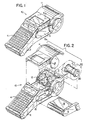
- a thermal transfer printing machine 10 which employs the preferred embodiment of the present invention includes a molded plastic housing 2 that supports a keyboard 4 on its front surface and a display 6 positioned above the keyboard 4.
- a cavity 12 formed in the housing 2 above the display 6 receives a spool 20 containing labeling media 22.
- the labeling media 22 is formed as a roll which is carried by the spool 20.
- the spool 20 is inserted into a receptacle cavity 12 on the printer 10 and the labeling media 22 is threaded past a print head 8, as shown in Fig. 3.
- a cover 11 enclosing the spool 20 and labeling media 22 in the receptacle cavity 12 is pivotally attached to the housing 2.
- the labeling media 22 is comprised of a carrier web 3 which supports a series of adhesive labels 1.
- the size, color, and type of label material carried by the spool 20 varies depending upon the particular print application.
- the labeling media 22 unrolls off the spool 20 as it is consumed by the printer 10.
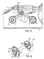
- An ink ribbon cartridge 5, shown in Figs. 2, 3 and 6, having a thermal transfer ribbon 13 disposed within the cartridge 5 is inserted into a cavity 15 in the side of the printing machine housing 2 and received by a print frame assembly 40.
- the ribbon cartridge 5, shown in Fig 2, rotatably accommodates a supply spool 34 containing the ribbon 13 for thermal transfer printing onto a labeling media 22 and the take up spool 32 for taking up the inked ribbon 13 as it is used in the thermal transfer printing process.
- the ink ribbon 13 is taken up by the supply spool 34 and ribbon 13 is unwound from the take up spool 32.
- a thermal print head 8 in the printing machine 10 is arranged to cooperate with the thermal transfer ribbon 13 and the labeling media 22 such that the print head 8 can print characters or symbols on the labeling media. This is described in greater detail in U.S. Patent No. 5,078,523 which is incorporated herein by reference.
- a cam mechanism within the printing machine 10 urges the print head 8 into close abutting relation with the labeling media 22 and ribbon 13 captured between a drive roller 30 and the print head 8.
- Circuitry in the printing machine 10 drives the drive roller 30 and a take up spool 32 to advance the labeling media 22 and ribbon 13.
- the electronics of the machine 10 energizes pixels on the thermal transfer head 8 as the labeling media 22 and ribbon 13 advance past the head 8.
- the head pixels are variously energized to imprint the character on the labeling media 22. This is described in greater detail in U.S. Patent No. 5,078,523 which has been incorporated herein by reference.
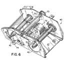
- the stepping motor gear mechanism 21 is engageably driven by a stepping motor 72 mounted in the print frame assembly 40.
- the print frame assembly 40 is mounted within the printing machine housing 2.
- the labeling media 22 and ribbon 13 are advanced past the print head 8 by a drive roller 30 that maintains the ribbon 13 and labeling media 22 in close cooperation with the print head 8.
- the drive roller 30 is rotatably driven by a bidirectional stepping motor 72 shown in Fig. 6.
- a delay is introduced in the bidirectional stepping motor gear mechanism 21 to pretension the ribbon 13 prior to feeding labeling media 22 and ribbon 13 past the print head 8.
- the essence of the invention is the delay between reversing the ink ribbon tension and the rotation of the drive roller 30.
- the drive roller 30, which advances the labeling media 22 and ribbon 13, stalls momentarily while the spindle 42 or 43 that will drive the spool, winding ribbon thereon, begins pulling the ribbon 13 in the desired direction. This has the effect of pulling all the slack out of the ribbon 13 before the labeling media 22 and ribbon 13 begin to feed past the print head 8.
- the introduction of the delay prevents wrinkles from developing in the ink ribbon 13 and being pulled over the print head 8.
- a stepping motor 72 mounted to the inside of a U-shaped print frame 47 has a rotatable shaft 80 extending through a wall of the print frame 47.
- a pinion 82 mounted on the rotatable shaft 80 engages outer gear teeth 84 of a motor idler gear 86 rotatably mounted to the print frame 47.
- Inner gear teeth 88 of the motor idler gear 86 engage an outer backlash gear 90 of the backlash idler gear assembly 92.
- the backlash idler gear assembly 92 comprises the outer backlash gear 90 and an inner backlash gear 94.
- the inner backlash gear 94 is mounted for rotation about the same axis 96 as the outer backlash gear 90.
- Extensions 98 formed on one face of the inner backlash gear 94 extends axially through corresponding slots 100 formed in the face of the outer backlash gear 90.
- the extensions 98 couple the rotational motion to the inner backlash gear 94.
- these extensions 98 are smaller than the slots 100, when this gear 90 changes direction, the gear 94 is not driven for a short interval. This interval is determined by the relative sizes of the extensions 98 and slots 100.
- the inner backlash gear 94 engages a drive roller gear 70 that is rotatably mounted on the print frame 47 and rigidly attached to the drive roller 30.
- the drive roller 30 also urges the ink ribbon 13 and labeling media 22 in close proximity to the print head 8 along the ribbon and media paths while advancing the labeling media 22 and ribbon 13 past the print head 8 during the printing process.
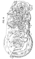
- the stepping motor gear mechanism 21 rotatably drives the take up and supply spools, 32 and 34, by rotatably engaging drive spindles.
- the outer backlash gear 90 engages a pair of idler gears, 102 and 106, rotatably mounted to the print frame 47.
- the first idler gear 102 of the pair of idler gears engages a take up spool spindle gear 104.
- the second idler gear 106 of the pair of idler gears engages the supply spool spindle gear 108.
- the spindle gears, 104 and 108 drivingly engage the spindles, 42 and 43, through spring clutches, 110 and 112 combined with one-way roller clutches (not shown) which are internal to the spindles, 42 and 43.
- Spindle gears, 104 and 108 are sized to "overdrive" the spools, 32 and 34.
- spool 32 In the forward direction, spool 32 is overdriven when it can take up the ribbon 13 faster than the drive roller 30 can feed the ribbon 13, thereby creating a tension in the ribbon 13 between the drive roller 30 and the take up spool 32.
- the resistance of the slip clutch 112 determines how much tension is in the ribbon 13 past the drive roller 30.
- spool 34 takes up the ribbon 13 and slip clutch 110 determines how much tension is in the ribbon 13 past the drive roller 30.
- the ribbon spool When the spindle is acting as the supply, the ribbon spool is rotating freely compared to the spool taking up the ribbon. In the forward direction, the tension on the ribbon 13 between the drive roller 30 and the supply spool 34 is then determined by the drag on the spool 34 provided the components inside the cartridge 5. In the reverse direction, spool 32 acts as the supply spool and the drag on the spool 32 provided by the cartridge 5 components determines the ribbon tension as the ribbon feeds toward the print head 8.
- the ink cartridge 5 is fully described in copending application THERMAL TRANSFER RIBBON CARTRIDGE, (PCT/US99/02843) filed simultaneously with the present patent application which has been incorporated by reference herein.
- the delay introduced into the gear mechanism 21 by the backlash gear assembly 92 ensures that tension is maintained in the ribbon 13 on both sides of the print head 8 when the labeling media 22 and ribbon 13 reverses direction.
- the presence of the ribbon tension reduces wasting labeling media 22 by minimizing the possibility of a ribbon wrinkle passing over the print head 8.
- the present embodiment does not advance or reverse the labeling media and ribbon independent of each other, therefore conserving ink ribbon is not an objective of the embodiment.
- the present invention of introducing a delay between reversing the ribbon tension and the advancing the ribbon in the reverse direction will minimize ribbon wrinkling whether or not the ribbon and labeling media are capable of advancing and reversing independent of each other.
- the preferred embodiment introduces the delay in a stepping motor gear mechanism by introducing a predetermined backlash in the gear mechanism of the ribbon transmission system, however, a pulley and belt system is another arrangement that could be used.
Claims (8)
- Verfahren zum Gespannthalten eines Farbbandes beim Umkehrung der Vorschubrichtung in einem Hand-Etikettendrucker, in welchem ein Farbband und ein Etikettenmedium die Vorschubrichtung umkehren können, aufweisend:Anhalten der Farbbandbewegung von einer ersten rotierenden Spule zu einer zweiten rotierenden Spule durch Stoppen eines Antriebsmechanismus;Drehen der ersten Spule in die Umkehrrichtung zur Spannung des Farbbandes über ein Zeitintervall, nachdem die erste Spule zu rotieren beginnt, wobei sich die zweite Spule relativ zur ersten Spule frei dreht, wenn sich das Farbband von der zweiten Spule abwickelt; unddarauf folgendes Einrücken des Antriebsmechanismus zur Bewegung des Farbbandes in der Umkehrrichtung von der zweiten Spule zur ersten Spule.
- Verfahren nach Anspruch 1, in welchem das Einrücken des Antriebsmechanismus zur Bewegung des Farbbandes auch das Etikettenmedium bewegt.
- Verfahren nach Anspruch 1, in welchem die Drehung der ersten Spule zum Spannen des Farbbandes auch vom Antriebsmechanismus erfolgt.
- Verfahren nach Anspruch 3, in welchem das Zeitintervall durch ein Getriebeorgan mit Spiel im Antriebsmechanismus hervorgerufen wird.
- Verfahren nach Anspruch 3, in welchem der Antriebsmechanismus einen Schrittmotor umfaßt, der über eine vorbestimmte Anzahl von Schritten rotiert, um das Band während des Zeitintervalls zu spannen, und der das Farbband eine vorbestimmte Anzahl von Schritten bewegt, nachdem der Antriebsmechanismus eingerückt ist.
- Bidirektionales Farbband-Transmissionssystem, aufweisend:einen Zweirichtungs-Motor, der eine rotierende Welle hat;ein äußeres Getriebeorgan mit Spiel, welches durch die Drehung der Motorwelle in Drehung versetzt wird;ein inneres Antriebsorgan mit Spiel, das in das äußere Antriebsorgan mit Spiel zur Drehung des äußeren Antriebsorgans mit Spiel eingerückt ist, wobei das Einrücken zwischen dem äußeren und dem inneren Antriebsorgan mit Spiel ein Intervall, währenddessen das innere Antriebsorgan mit Spiel nicht gedreht wird, jedes Mal vorsieht, wenn das äußere Antriebsorgan mit Spiel die Drehrichtung wechselt;eine Einrichtung, die vom äußeren Antriebsorgan mit Spiel angetrieben wird, zum Drehen von Antriebsspindeln zum Aufwickeln eines Farbbandes, das an einem Druckkopf vorbei vorgeschoben wird; undeine Antriebsrolleneinrichtung, die vom inneren Antriebsorgan mit Spiel angetrieben wird, zum Bewegen des Bandes und Etikettenmediums am Druckkopf vorbei.
- Bidirektionales Farbband-Transmissionssystem nach Anspruch 6, in welchem das Einrücken zwischen dem äußeren Antriebsorgan mit Spiel und mit dem inneren Antriebsorgan mit Spiel durch Schlitze vorgesehen wird, die in einer Stirnseite eines dieser Antriebsorgane ausgebildet sind, und durch Ansätze, die auf einer Stirnseite des anderen Antriebsorganes ausgebildet sind, und in welchem die Ansätze sich in diese Schlitze erstrecken und das Intervall dadurch hervorgerufen wird, daß die Schlitze größer als die Ansätze ausgebildet sind.
- Bidirektionales Farbband-Transmissionssystem nach Anspruch 6, in welchem die durch das äußere Antriebsorgan mit Spiel angetriebene Einrichtung ein Paar Spindel-Zwischenräder umfaßt, die individuelle Rutschkupplungen aufweisen, wobei das Band übersteuert wird, woraufhin die Kupplungen zum Rutschen gebracht werden, wenn die Kupplung eine der Spindeln antreibt, die das Band aufwickelt.
Applications Claiming Priority (3)
| Application Number | Priority Date | Filing Date | Title |
|---|---|---|---|
| US33342 | 1998-03-02 | ||
| US09/033,342 US5951177A (en) | 1998-03-02 | 1998-03-02 | Method and apparatus for maintaining ribbon tension |
| PCT/US1999/002915 WO1999044835A1 (en) | 1998-03-02 | 1999-02-10 | Method and apparatus for maintaining ribbon tension |
Publications (2)
| Publication Number | Publication Date |
|---|---|
| EP1060084A1 EP1060084A1 (de) | 2000-12-20 |
| EP1060084B1 true EP1060084B1 (de) | 2002-05-15 |
Family
ID=21869857
Family Applications (1)
| Application Number | Title | Priority Date | Filing Date |
|---|---|---|---|
| EP99905938A Expired - Lifetime EP1060084B1 (de) | 1998-03-02 | 1999-02-10 | Verfahren und vorrichtung zum gespannhalten eines farbbandes |
Country Status (9)
| Country | Link |
|---|---|
| US (2) | US5951177A (de) |
| EP (1) | EP1060084B1 (de) |
| JP (1) | JP3498844B2 (de) |
| CN (1) | CN1107597C (de) |
| AU (1) | AU740491B2 (de) |
| BR (1) | BR9908469A (de) |
| CA (1) | CA2321770C (de) |
| DE (1) | DE69901490T2 (de) |
| WO (1) | WO1999044835A1 (de) |
Families Citing this family (26)
| Publication number | Priority date | Publication date | Assignee | Title |
|---|---|---|---|---|
| JP3976477B2 (ja) * | 2000-06-16 | 2007-09-19 | 日本ビクター株式会社 | 熱転写記録装置 |
| ES2330154T5 (es) | 2000-09-11 | 2017-10-25 | Videojet Technologies, Inc. | Dispositivo de accionamiento de cinta y aparato de impresión |
| US20030027051A1 (en) * | 2001-07-23 | 2003-02-06 | Kejha Joseph B. | Manufacturing method and structure of electrodes for lithium based electrochemical devices |
| US6830391B2 (en) | 2001-09-21 | 2004-12-14 | Panduit Corp. | Media cartridge with printed circuit board for use in a printing system |
| US6672780B2 (en) | 2001-09-21 | 2004-01-06 | Panduit Corp. | Thermal printhead mechanism |
| US6848845B2 (en) * | 2002-05-08 | 2005-02-01 | Zih Corp. | Thermal ribbon cartridge or roll with slack ribbon retraction |
| US7040822B2 (en) | 2003-06-04 | 2006-05-09 | Hellermanntyton Corporation | Portable printing system |
| US6910819B2 (en) * | 2003-08-12 | 2005-06-28 | Brady Worldwide, Inc. | Printer cartridge |
| US7070347B2 (en) * | 2003-08-12 | 2006-07-04 | Brady Worldwide, Inc. | Printer with a pivoting gear mechanism |
| JP4001132B2 (ja) * | 2004-07-08 | 2007-10-31 | セイコーエプソン株式会社 | テープ印刷装置 |
| MX2007006388A (es) | 2004-11-30 | 2007-06-20 | Panduit Corp | Sistema y metodo de etiquetado basado en el mercado. |
| WO2006099625A2 (en) * | 2005-03-16 | 2006-09-21 | Panduit Corporation | Hand-held thermal transfer printer for labeling |
| US9061522B2 (en) * | 2005-03-16 | 2015-06-23 | Panduit Corp. | Reversible printer assembly |
| US8475914B2 (en) * | 2005-05-09 | 2013-07-02 | Brady Worldwide, Inc. | Thick, printable labels suitable for use in a thermal transfer printer |
| GB2448302B (en) | 2007-03-07 | 2009-04-08 | Zipher Ltd | Tape drive |
| GB2448395B (en) * | 2007-03-07 | 2009-05-06 | Zipher Ltd | Tape drive |
| WO2008119927A1 (en) | 2007-03-31 | 2008-10-09 | Zipher Limited | Tape drive |
| WO2009152311A1 (en) * | 2008-06-13 | 2009-12-17 | Brady Worldwide, Inc. | Printer drive train for providing and maintaining ribbon tension |
| JP5167998B2 (ja) * | 2008-07-16 | 2013-03-21 | セイコーエプソン株式会社 | ベルト駆動装置及び記録装置 |
| AU2010308184A1 (en) * | 2009-10-13 | 2012-05-17 | Brady Worldwide Inc. | Apparatus for labelling |
| JP5467878B2 (ja) * | 2010-01-22 | 2014-04-09 | アルプス電気株式会社 | 中間転写媒体走行装置およびこれを用いた熱転写ラインプリンタ |
| WO2014084169A1 (ja) * | 2012-11-30 | 2014-06-05 | 日本電産サンキョー株式会社 | インクリボンカセット、インクリボンカートリッジ、印刷装置および印刷装置の制御方法 |
| US10252874B2 (en) | 2017-02-20 | 2019-04-09 | Datamax-O'neil Corporation | Clutch bearing to keep media tension for better sensing accuracy |
| CN109263312B (zh) * | 2018-11-30 | 2023-09-01 | 硕方科技(北京)有限公司 | 一种打印机介质传动离合制动组件及打印机 |
| CN110978803B (zh) * | 2019-11-05 | 2020-12-01 | 厦门汉印电子技术有限公司 | 热转印打印机及其电机驱动方法、装置以及存储介质 |
| CN112831948B (zh) * | 2020-12-31 | 2022-11-04 | 德州学院 | 一种环保型服装染色设备 |
Family Cites Families (44)
| Publication number | Priority date | Publication date | Assignee | Title |
|---|---|---|---|---|
| US3554349A (en) * | 1968-06-04 | 1971-01-12 | Gen Electric | High-speed printer having improved ribbon tensioning and reversing drive mechanism |
| US3926110A (en) * | 1974-04-11 | 1975-12-16 | Pitney Bowes Inc | Hand held ticket printer applicator |
| US4050375A (en) * | 1976-02-05 | 1977-09-27 | Pitney-Bowes, Inc. | Label printing apparatus |
| EP0000657B2 (de) * | 1977-07-28 | 1988-12-07 | Inc. Monarch Marking Systems | Etikettiermaschinen. |
| US4440248A (en) * | 1980-02-09 | 1984-04-03 | Teraoka Seikosho Co., Ltd. | Bar code printer |
| US4556442A (en) * | 1981-05-29 | 1985-12-03 | Monarch Marking Systems, Inc. | Hand-held electrically selectable labeler |
| US4407692A (en) * | 1981-05-29 | 1983-10-04 | Monarch Marking Systems, Inc. | Hand-held electrically selectable labeler |
| US4497682A (en) * | 1981-05-29 | 1985-02-05 | Monarch Marking Systems, Inc. | Hand-held electrically selectable labeler |
| JPS58155246U (ja) * | 1982-04-12 | 1983-10-17 | ブラザー工業株式会社 | 熱転写プリンタ |
| US4497683A (en) | 1982-05-03 | 1985-02-05 | At&T Bell Laboratories | Process for producing dielectrically isolated silicon devices |
| JPS591288A (ja) * | 1982-06-29 | 1984-01-06 | Sato :Kk | 連続値札印字装置 |
| US4544434A (en) * | 1984-02-28 | 1985-10-01 | Monarch Marking Systems, Inc. | Hand-held labeler |
| US4490206A (en) * | 1984-02-28 | 1984-12-25 | Monarch Marking Systems, Inc. | Hand-held labeler |
| US4473426A (en) * | 1983-04-12 | 1984-09-25 | Monarch Marking Systems, Inc. | Labeler |
| US4477305A (en) * | 1983-04-12 | 1984-10-16 | Monarch Marking Systems, Inc. | Labeler |
| US4584048A (en) * | 1983-04-12 | 1986-04-22 | Monarch Marking Systems, Inc. | Labeler |
| US4511422A (en) * | 1984-02-28 | 1985-04-16 | Monarch Marking Systems, Inc. | Hand-held labeler |
| US4498947A (en) * | 1984-02-28 | 1985-02-12 | Monarch Marking Systems, Inc. | Hand-held labeler |
| US4724033A (en) * | 1984-04-03 | 1988-02-09 | Monarch Marking Systems, Inc. | Hand-held labeler having improved web position sensing and print head control |
| US4680078A (en) * | 1984-04-03 | 1987-07-14 | Monarch Marking Systems, Inc. | Hand-held labeler having improved web position sensing and print head control |
| US4630538A (en) * | 1985-04-22 | 1986-12-23 | Cushman Larry A | Portable label maker |
| US4712115A (en) * | 1985-05-10 | 1987-12-08 | Kabushiki Kaisha Toshiba | Thermal-transfer printer |
| JPS6241070A (ja) * | 1985-08-20 | 1987-02-23 | Sanyo Electric Co Ltd | 熱転写記録装置 |
| US4655129A (en) * | 1985-10-11 | 1987-04-07 | W. H. Brady Co. | Marker sleeve processing machine |
| US5246298A (en) * | 1986-07-15 | 1993-09-21 | Monarch Marking Systems, Inc. | Ink ribbon cartridge and installation methods relating thereto |
| JPS63185672A (ja) * | 1987-01-28 | 1988-08-01 | Hitachi Ltd | 熱転写プリンタのリボンカセツト |
| US4788558A (en) * | 1987-02-06 | 1988-11-29 | Intermec Corporation | Method and apparatus for controlling tension in tape progressed along a feed path |
| US5052832A (en) * | 1987-05-25 | 1991-10-01 | Seiko Epson Corporation | Print head and roller biasing mechanism for a hand held thermal printer |
| JPH0162059U (de) * | 1987-10-14 | 1989-04-20 | ||
| US4917514A (en) * | 1988-02-01 | 1990-04-17 | Kroy Inc. | Thermal printing device and tape supply cartridge embodying a tape cut-off mechanism |
| US4815874A (en) * | 1988-02-01 | 1989-03-28 | Kroy Inc. | Thermal printer and tape-ribbon cartridge with cut-off mechanism |
| US5111216A (en) * | 1988-07-12 | 1992-05-05 | Kroy Inc. | Tape supply cartridge for portable thermal printer |
| US5607244A (en) * | 1988-12-29 | 1997-03-04 | Tohoku Ricoh Co., Ltd. | Thermal printer with paper and ribbon separator |
| JP2544485B2 (ja) * | 1989-07-14 | 1996-10-16 | 株式会社テック | プリンタ |
| US5138335A (en) * | 1989-10-16 | 1992-08-11 | Tokyo Electric Co., Ltd. | Thermal printer with removable ribbon unit |
| JPH0471877A (ja) * | 1990-07-13 | 1992-03-06 | Tokyo Electric Co Ltd | 転写式プリンタ |
| US5211491A (en) * | 1991-04-10 | 1993-05-18 | Eastman Kodak Company | Thermal transfer cartridge integral lock |
| JPH0532031A (ja) * | 1991-05-23 | 1993-02-09 | Tokyo Electric Co Ltd | インクリボンカートリツジ |
| US5284396A (en) * | 1991-07-29 | 1994-02-08 | Kanzaki Paper Mfg. Co., Ltd. | Ribbon feeder for a printer having a tension mechanism |
| JPH05147295A (ja) * | 1991-11-30 | 1993-06-15 | Murata Mach Ltd | インクリボン式記録装置 |
| JPH0768814A (ja) * | 1993-09-06 | 1995-03-14 | Brother Ind Ltd | テープ印字装置 |
| EP0648609B1 (de) * | 1993-10-15 | 2001-01-03 | Monarch Marking Systems, Inc. | Drucker |
| FR2713552B1 (fr) * | 1993-12-15 | 1996-02-09 | Sagem | Sabot de chargement de ruban encreur pour imprimante à impression par transfert thermique. |
| US5820277A (en) * | 1996-05-10 | 1998-10-13 | Monarch Marking Systems, Inc. | Printer |
-
1998
- 1998-03-02 US US09/033,342 patent/US5951177A/en not_active Expired - Lifetime
-
1999
- 1999-02-10 DE DE69901490T patent/DE69901490T2/de not_active Expired - Lifetime
- 1999-02-10 EP EP99905938A patent/EP1060084B1/de not_active Expired - Lifetime
- 1999-02-10 BR BR9908469-4A patent/BR9908469A/pt not_active IP Right Cessation
- 1999-02-10 AU AU25976/99A patent/AU740491B2/en not_active Ceased
- 1999-02-10 WO PCT/US1999/002915 patent/WO1999044835A1/en active IP Right Grant
- 1999-02-10 CN CN99803480A patent/CN1107597C/zh not_active Expired - Lifetime
- 1999-02-10 CA CA002321770A patent/CA2321770C/en not_active Expired - Fee Related
- 1999-02-10 JP JP2000534411A patent/JP3498844B2/ja not_active Expired - Fee Related
- 1999-06-23 US US09/338,863 patent/US6142686A/en not_active Expired - Lifetime
Also Published As
| Publication number | Publication date |
|---|---|
| CN1291942A (zh) | 2001-04-18 |
| US6142686A (en) | 2000-11-07 |
| AU740491B2 (en) | 2001-11-08 |
| EP1060084A1 (de) | 2000-12-20 |
| JP3498844B2 (ja) | 2004-02-23 |
| CA2321770A1 (en) | 1999-09-10 |
| BR9908469A (pt) | 2000-12-05 |
| US5951177A (en) | 1999-09-14 |
| WO1999044835A1 (en) | 1999-09-10 |
| CA2321770C (en) | 2004-07-06 |
| CN1107597C (zh) | 2003-05-07 |
| DE69901490D1 (de) | 2002-06-20 |
| JP2002505215A (ja) | 2002-02-19 |
| DE69901490T2 (de) | 2002-11-14 |
| AU2597699A (en) | 1999-09-20 |
Similar Documents
| Publication | Publication Date | Title |
|---|---|---|
| EP1060084B1 (de) | Verfahren und vorrichtung zum gespannhalten eines farbbandes | |
| US7070347B2 (en) | Printer with a pivoting gear mechanism | |
| US6113293A (en) | Label printer having lever actuated cutter | |
| EP1308298B1 (de) | Drucker mit von einem multifunktionellen Hebel aktivierten Mechanismus | |
| US5427460A (en) | Label printer and label strip feed mechanism therefor | |
| EP0327073B1 (de) | Thermo-Drucker und seine Bandkassette | |
| CA2534516C (en) | Wire marker label media | |
| US6068420A (en) | Printer with an integrally formed spring for biasing the printhead | |
| EP1066973B1 (de) | Drucker und Haspel | |
| MXPA00008589A (en) | Method and apparatus for maintaining ribbon tension | |
| WO1999044834A1 (en) | Thermal transfer ribbon cartridge | |
| GB2315044A (en) | A drive mechanism for tape |
Legal Events
| Date | Code | Title | Description |
|---|---|---|---|
| PUAI | Public reference made under article 153(3) epc to a published international application that has entered the european phase |
Free format text: ORIGINAL CODE: 0009012 |
|
| 17P | Request for examination filed |
Effective date: 20000905 |
|
| AK | Designated contracting states |
Kind code of ref document: A1 Designated state(s): BE DE FR GB IT |
|
| GRAG | Despatch of communication of intention to grant |
Free format text: ORIGINAL CODE: EPIDOS AGRA |
|
| 17Q | First examination report despatched |
Effective date: 20010523 |
|
| GRAG | Despatch of communication of intention to grant |
Free format text: ORIGINAL CODE: EPIDOS AGRA |
|
| GRAH | Despatch of communication of intention to grant a patent |
Free format text: ORIGINAL CODE: EPIDOS IGRA |
|
| GRAH | Despatch of communication of intention to grant a patent |
Free format text: ORIGINAL CODE: EPIDOS IGRA |
|
| GRAA | (expected) grant |
Free format text: ORIGINAL CODE: 0009210 |
|
| AK | Designated contracting states |
Kind code of ref document: B1 Designated state(s): BE DE FR GB IT |
|
| REG | Reference to a national code |
Ref country code: GB Ref legal event code: FG4D |
|
| REF | Corresponds to: |
Ref document number: 69901490 Country of ref document: DE Date of ref document: 20020620 |
|
| ET | Fr: translation filed | ||
| PLBE | No opposition filed within time limit |
Free format text: ORIGINAL CODE: 0009261 |
|
| STAA | Information on the status of an ep patent application or granted ep patent |
Free format text: STATUS: NO OPPOSITION FILED WITHIN TIME LIMIT |
|
| 26N | No opposition filed |
Effective date: 20030218 |
|
| PGFP | Annual fee paid to national office [announced via postgrant information from national office to epo] |
Ref country code: IT Payment date: 20100219 Year of fee payment: 12 |
|
| PGFP | Annual fee paid to national office [announced via postgrant information from national office to epo] |
Ref country code: BE Payment date: 20100215 Year of fee payment: 12 |
|
| BERE | Be: lapsed |
Owner name: *BRADY WORLDWIDE INC. Effective date: 20110228 |
|
| PG25 | Lapsed in a contracting state [announced via postgrant information from national office to epo] |
Ref country code: BE Free format text: LAPSE BECAUSE OF NON-PAYMENT OF DUE FEES Effective date: 20110228 |
|
| PG25 | Lapsed in a contracting state [announced via postgrant information from national office to epo] |
Ref country code: IT Free format text: LAPSE BECAUSE OF NON-PAYMENT OF DUE FEES Effective date: 20110210 |
|
| REG | Reference to a national code |
Ref country code: DE Ref legal event code: R082 Ref document number: 69901490 Country of ref document: DE Representative=s name: ADVOTEC. PATENT- UND RECHTSANWAELTE, DE |
|
| REG | Reference to a national code |
Ref country code: FR Ref legal event code: PLFP Year of fee payment: 18 |
|
| REG | Reference to a national code |
Ref country code: FR Ref legal event code: PLFP Year of fee payment: 19 |
|
| REG | Reference to a national code |
Ref country code: FR Ref legal event code: PLFP Year of fee payment: 20 |
|
| PGFP | Annual fee paid to national office [announced via postgrant information from national office to epo] |
Ref country code: GB Payment date: 20180207 Year of fee payment: 20 Ref country code: DE Payment date: 20180130 Year of fee payment: 20 |
|
| PGFP | Annual fee paid to national office [announced via postgrant information from national office to epo] |
Ref country code: FR Payment date: 20180111 Year of fee payment: 20 |
|
| REG | Reference to a national code |
Ref country code: DE Ref legal event code: R071 Ref document number: 69901490 Country of ref document: DE |
|
| REG | Reference to a national code |
Ref country code: GB Ref legal event code: PE20 Expiry date: 20190209 |
|
| PG25 | Lapsed in a contracting state [announced via postgrant information from national office to epo] |
Ref country code: GB Free format text: LAPSE BECAUSE OF EXPIRATION OF PROTECTION Effective date: 20190209 |