EP1059685A2 - Carbon electrode material for vanadium-based redox-flow type battery - Google Patents
Carbon electrode material for vanadium-based redox-flow type battery Download PDFInfo
- Publication number
- EP1059685A2 EP1059685A2 EP00112205A EP00112205A EP1059685A2 EP 1059685 A2 EP1059685 A2 EP 1059685A2 EP 00112205 A EP00112205 A EP 00112205A EP 00112205 A EP00112205 A EP 00112205A EP 1059685 A2 EP1059685 A2 EP 1059685A2
- Authority
- EP
- European Patent Office
- Prior art keywords
- electrode material
- woven fabric
- carbon electrode
- carbon
- material according
- Prior art date
- Legal status (The legal status is an assumption and is not a legal conclusion. Google has not performed a legal analysis and makes no representation as to the accuracy of the status listed.)
- Granted
Links
Images

Classifications
-
- H—ELECTRICITY
- H01—ELECTRIC ELEMENTS
- H01M—PROCESSES OR MEANS, e.g. BATTERIES, FOR THE DIRECT CONVERSION OF CHEMICAL ENERGY INTO ELECTRICAL ENERGY
- H01M8/00—Fuel cells; Manufacture thereof
- H01M8/18—Regenerative fuel cells, e.g. redox flow batteries or secondary fuel cells
- H01M8/184—Regeneration by electrochemical means
- H01M8/188—Regeneration by electrochemical means by recharging of redox couples containing fluids; Redox flow type batteries
-
- C—CHEMISTRY; METALLURGY
- C01—INORGANIC CHEMISTRY
- C01B—NON-METALLIC ELEMENTS; COMPOUNDS THEREOF; METALLOIDS OR COMPOUNDS THEREOF NOT COVERED BY SUBCLASS C01C
- C01B32/00—Carbon; Compounds thereof
- C01B32/20—Graphite
-
- H—ELECTRICITY
- H01—ELECTRIC ELEMENTS
- H01M—PROCESSES OR MEANS, e.g. BATTERIES, FOR THE DIRECT CONVERSION OF CHEMICAL ENERGY INTO ELECTRICAL ENERGY
- H01M4/00—Electrodes
- H01M4/86—Inert electrodes with catalytic activity, e.g. for fuel cells
- H01M4/96—Carbon-based electrodes
-
- C—CHEMISTRY; METALLURGY
- C01—INORGANIC CHEMISTRY
- C01P—INDEXING SCHEME RELATING TO STRUCTURAL AND PHYSICAL ASPECTS OF SOLID INORGANIC COMPOUNDS
- C01P2002/00—Crystal-structural characteristics
- C01P2002/60—Compounds characterised by their crystallite size
-
- C—CHEMISTRY; METALLURGY
- C01—INORGANIC CHEMISTRY
- C01P—INDEXING SCHEME RELATING TO STRUCTURAL AND PHYSICAL ASPECTS OF SOLID INORGANIC COMPOUNDS
- C01P2002/00—Crystal-structural characteristics
- C01P2002/70—Crystal-structural characteristics defined by measured X-ray, neutron or electron diffraction data
- C01P2002/78—Crystal-structural characteristics defined by measured X-ray, neutron or electron diffraction data by stacking-plane distances or stacking sequences
-
- C—CHEMISTRY; METALLURGY
- C01—INORGANIC CHEMISTRY
- C01P—INDEXING SCHEME RELATING TO STRUCTURAL AND PHYSICAL ASPECTS OF SOLID INORGANIC COMPOUNDS
- C01P2006/00—Physical properties of inorganic compounds
- C01P2006/80—Compositional purity
-
- Y—GENERAL TAGGING OF NEW TECHNOLOGICAL DEVELOPMENTS; GENERAL TAGGING OF CROSS-SECTIONAL TECHNOLOGIES SPANNING OVER SEVERAL SECTIONS OF THE IPC; TECHNICAL SUBJECTS COVERED BY FORMER USPC CROSS-REFERENCE ART COLLECTIONS [XRACs] AND DIGESTS
- Y02—TECHNOLOGIES OR APPLICATIONS FOR MITIGATION OR ADAPTATION AGAINST CLIMATE CHANGE
- Y02E—REDUCTION OF GREENHOUSE GAS [GHG] EMISSIONS, RELATED TO ENERGY GENERATION, TRANSMISSION OR DISTRIBUTION
- Y02E60/00—Enabling technologies; Technologies with a potential or indirect contribution to GHG emissions mitigation
- Y02E60/30—Hydrogen technology
- Y02E60/50—Fuel cells
Definitions
- the present invention relates to a carbon electrode material used for a vanadium-based redox-flow type battery and, more particularly to, such a carbon electrode material which is excellent in the energy efficiency of the overall battery system and also which has less changes in its performance accompanied by a prolonged period of services.
- the electrode has been developed intensively as a key factor of the battery performance.
- Some types of electrodes do not act as an active material but act as a reaction field which promotes the electrochemical reaction of active materials, often coining in of carbon materials due to their good electro-conductivity and chemical resistance.
- a carbon fiber assembly having a chemical resistance, electro-conductivity, and liquid flowability is used.
- the redox-flow type battery has been changed from a type using an aqueous solution of iron and hydrochloric acid in its positive electrode and an aqueous solution of chromium and hydrochloric acid in negative to a type using in both electrodes an aqueous solution of vanadium sulfate having a higher electromotive force and thus improved to have a higher energy density. It is recently having a further enhanced energy density by the development for a higher concentration of active materials employed therein.
- the redox-flow type battery mainly comprises, as shown in FIG. 1, external tanks 6 and 7 for storing an electrolyte solution and an electrolytic cell EC, in such a configuration that while pumps 8 and 9 are sending the electrolyte solution containing an active material from the external tanks 6 and 7 to the electrolytic cell EC, electrodes incorporated in the electrolytic cell EC performs electrochemical conversion, i.e. charge-discharge.
- the electrolytic cell In charge-discharge in general, the electrolytic cell has such a liquid flow-through type structure as shown in FIG. 1, in order to circulate an electrolyte solution between the external tanks and the electrolytic cell itself.
- a liquid flow-through type electrolytic cell is called a single cell and used, as a minimum unit, independently or in a multi-layer stack. Since the electrochemical reaction within a liquid flow-through type electrolytic cell occurs as a non-uniform phase reaction on the surface of an electrode, it is generally accompanied by a two-dimensional electrolytic-reaction field. Since its electrolytic-reaction field is a two-dimensional one, the electrolytic cell suffers a problem that it has a smaller reaction amount per unit volume.
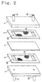
- FIG. 2 shows an exploded perspective view of a liquid flow-through type electrolytic cell having three-dimensional electrodes.
- this electrolytic cell between counter-opposing two collector plates 1 an ion exchange membrane 3 is interposed, flow passages 4a and 4b for an electrolyte solution along the inner surface of the collector plates 1 are formed by a spacer 2.
- At least one of these flow passages 4a and 4b has therein an electrode material 5 such as a carbon fiber assembly, thus constituting a three-dimensional electrode.
- the collector plate 1 is provided with a liquid inlet 10 and a liquid outlet 11 for the electrolyte solution.
- V 2+ releases electrons, to be oxidized into V 3+
- V 5+ into V 4+ (actually ions containing oxygen).
- the electrolyte solution at the negative electrode runs short of SO 4 2- and that at the positive electrode has an excessive amount of SO 4 2- so that SO 4 2- moves from the positive electrode through the ion-exchange membrane to the negative electrode, thus maintaining a charge balance.
- H+ moves from the positive electrode through the ion-exchange membrane to the negative electrode, thus maintaining the charge balance.
- the reaction opposite to that for discharge proceeds.
- the electrode materials for vanadium-based redox-flow type batteries must have the following performance as their properties:
- Japanese Patent Publication No. Sho-60-232669 suggests that a carbonaceous material should be used as an electrode material for ion-chromium-based redox-flow type batteries, which has an quasi-graphite microcrystal having an average of 3.70 ⁇ or less of a ⁇ 002 ⁇ inter-facial spacing obtained with X-ray wide-angle analysis and an average of 9.0 ⁇ or more of a c-axial crystallite size and also that has a total acid functional group amount of at least 0.01 meq/g.
- Japanese Patent Publication No. Hei-5-234612 also suggests that carbonaceous fiber made from polyacrylonitrile-based fiber as a material should be used as an electrode material for an electrolytic cell of iron-chromium-based redox-flow type batteries, which has an quasi-graphite crystal structure with a ⁇ 002 ⁇ inter-facial spacing of 3.50 - 3.60 ⁇ as obtained with X-ray wide-angle analysis, and in which the number of the combination oxygen atoms is 10 - 25% of that of the carbon atoms on the surface.
- the total acid functional group amount must be 0.01 meq/g or more or the number of the combination oxygen atoms must be 10% or more of that of the carbon atoms on the carbonaceous material surface. Therefore, as found out recently, a vanadium-based redox-flow type battery presently under development having a higher active material concentration and also a higher viscosity provides a higher contact resistance between the carbonaceous material surface and the collector plate or that between the fiber and the fiber, resulting in the cell resistance being too high to obtain a high energy efficiency.
- the vanadium-based redox-flow type battery has strong oxidization force of the penta-valent ions of vanadium, the above-mentioned electrode material cannot provide sufficient oxidization resistance, so that the cell resistance increases as the charge-discharge cycle is repeated, thus increasing a change in (deterioration ratio of) the energy efficiency.
- the inventors of the present invention conducted intensive study and came up with a finding for completion of the present invention that for a carbon electrode material having a particular quasi-graphite crystal structure, by regulating both a surface acid functional group amount and a number of surface bound-nitrogen atoms within their respective particular ranges, the above-mentioned objects can be achieved.
- any carbon electrode material for vanadium-based redox-flow type batteries according to the present invention is such a carbon electrode material for a vanadium-based redox-flow type battery, comprising quasi-graphite crystal structure, wherein ⁇ 002 ⁇ spacing is 3.43 to 3.60 ⁇ , size of a crystallite in c axial direction is 15 to 33 ⁇ , and size of a crystallite in a axial direction is 30 to 70 ⁇ , each obtained by X-ray wide angle analysis, and having surface property obtained by XPS surface analysis wherein an amount of surface acidic functional groups is 0.1 to 1.2% relative to total number of surface carbon atoms and number of surface bound-nitrogen atoms is 5% or smaller relative to total number of surface carbon atoms.
- the above-mentioned surface acid functional group amount is 0.2 - 1.0% of the total number of the surface carbon atoms and the above-mentioned number of the surface bound-nitrogen atoms is 3% or less of the total number of the surface carbon atoms.
- the vanadium-based redox-flow type battery has therein a remarkably increased degree of wettability with an electrolyte solution, an increased area of the electrode's effective area (significantly larger than the geometrical area but smaller than the BET surface area), a largely improved degree of the electrode activity, and a largely enhanced electro-conductivity of the electrode surface.
- a carbon electrode material having such an quasi-graphite crystal structure has its electro-conductivity further improved and therefore enjoys more appropriate cell resistance and energy efficiency also with less fluctuations in energy efficiency which may be caused by repetition of the charge-discharge cycle.
- a carbon electrode material according to the present invention is used in a vanadium-based redox-flow type battery having its electrolyte-solution viscosity of 0.005Pa.s or higher at 25°C.
- the redox-flow type battery having such an electrolyte solution tends to have a higher contact resistance between the carbonaceous material surface and the collector plate or between the fiber and the fiber, so that the carbon electrode material according to the present invention having the above-mentioned function and effects is particularly useful.
- the carbon electrode material according to the present invention is used in a vanadium-based redox-flow type battery wherein its electrolyte solution contains 1.5 mol/l or more of vanadium ions. Since the redox-flow type battery having such an electrolyte solution has a strong oxidization force of the vanadium's penta-valent ions, as the charge-discharge cycle is repeated, the cell resistance increases due to the oxidization of the electrode material, thus causing the energy efficiency to deteriorate. Therefore, the carbon electrode material having the above-mentioned function and effects according to the present invention is particularly useful.
- a carbon electrode material for vanadium-based redox-flow type batteries according to the present invention is not limited to its tissue or micro-structure but preferably can be made larger in electrode area. Specifically it may include a spun yarn, a filament bundling yarn, a non-woven yarn, a fabric, a woven fabric, a special fabric (such as disclosed in Japanese Patent Publication No. Sho-63-200467) or a carbonaceous fiber assembly consisting of their hybrid tissue or a porous carbon substance, a carbon-carbon composite, a particulate carbon material, etc. Of these, a sheet consisting of these carbonaceous fibers, particularly carbonaceous fiber's non-woven fabrics is preferable from a viewpoint of handling, workability, and manufacturability.
- the non-woven fabric is appropriately made by opening a short fiber made infusible or flame resistant before baking (carbonization) and carding it to first create a web consisting of a few layers stacked and then treating it with a needle punch machine.
- the basis weight of the non-woven fabric is preferably 100 - 1000 g/m 2 , particularly 200 - 600 g/m 2 when it is 2 - 3 mm thick as sandwiched between the separator membrane and the collector plate in a filled state.
- a non-woven fabric that has its one face treated to have one or more a concave groove is preferably used from a viewpoint of liquid flowability.
- the groove has a width and a depth of at least 0.3 mm, particularly preferably 0.5 mm or more. That carbonaceous fiber non-woven fabric is larger than a thickness in the above-mentioned filled state, preferably about 1.5 times the thickness in the filled state. However, if it is too thick, it would break through the separator membrane by its compressive stress, so that preferably that stress is designed to be 1 kgf/cm2 or less.
- the above-mentioned carbonaceous fiber has preferably an average fiber diameter of 5 - 20 ⁇ m and an average length of 30 - 100 mm. Also, the carbonaceous fiber preferably is 1.1 to 5.5 dtex.
- the tensile strength is preferably 0.1 kg/cm 2 to avoid dropping in order to maintain the shape.
- the density of the filling layer sandwiched between the collector plates is preferably 0.05 g/cm 3 or more and the resilient strength is preferably 0.1 kgf/cm 2 or more.
- a carbon electrode material for vanadium-based redox-flow type batteries according to the present invention needs to have a quasi-graphite crystal structure which has a ⁇ 002 ⁇ inter-facial spacing obtained with X-ray wide-angle analysis of 3.43 - 3.60 ⁇ , a c-axial crystallite size of 15 - 33 ⁇ , and an a-axial crystallite size of 30 - 70 ⁇ .
- the above-mentioned ⁇ 002 ⁇ inter-facial spacing is 3.45 - 3.50 ⁇
- the above-mentioned c-axial crystallite size is 20 - 30 ⁇
- the above-mentioned a-axial crystallite size is 45 - 65 ⁇ .
- the ⁇ 002 ⁇ inter-facial spacing is known to take on various values from 3.35 ⁇ for graphite to a value in excess of 3.7 ⁇ for amorphous carbon, having various properties dependently.
- the electro-conducting resistance of the electrode material in the inner battery resistance cannot be ignored, thus resulting in an increase in the cell resistance (i.e. decrease in the voltage efficiency) to deteriorate the energy efficiency.
- the cell resistance increases as the charge-discharge cycle is repeated, thus deteriorating the energy efficiency.
- the above-mentioned carbon has distortion in its crystal structure or has a structure approximate to graphite, it tends to be decomposed due to sulfuric acid used in the electrolyte solution of, e.g., a vanadium-based redox-flow type battery.
- the specific resistance exceeds 10 -2 ⁇ cm, so that the electrode material's electro-conductive resistance component in the inner battery resistance (cell resistance) cannot be ignored, thus resulting in an increase in the cell resistance (i.e. decrease in the voltage efficiency) and a decrease in the energy efficiency. Also, the specific resistance tends to be deteriorated due to a prolonged period of service.
- the above-mentioned parameters may be controlled by the baking conditions, they can be also appropriately controlled without influenced by thew baking conditions too much by uniformly attaching metal salt which provide such tri-valent ions such as Al, Si, and Bi as much as 10 - 100 ppm as referred to metal ions to a carbon fiber material which has undergone initial air-oxidation, and by then baking (carbonizing) it.
- metal salt which provide such tri-valent ions such as Al, Si, and Bi as much as 10 - 100 ppm as referred to metal ions
- a microscopic Raman spectrometer manufactured by Jobanne-Yvonne Atago-Bussan
- the peak strengths are both subjected to base-line correction and then the measured wavelength is approximated with a Lorenz function; with this, they are calculated based on the highest point and the peak's half-value, half-width is obtained based on a half value of a peak width at a half of the peak strength.
- the carbon electrode material according to the present invention preferably has a quasi-graphite crystal structure that has 0.50 - 0.90 as the stacked structure ratio based on a peak strength of the ⁇ 002 ⁇ diffraction obtained with X-ray wide-angle analysis. If the stacked structure ratio is less than 0.50, the specific resistance exceeds 10 -2 ⁇ cm, so that the electrode material's electro-conductive resistance component of the inner battery resistance (cell resistance) cannot be ignored, thus resulting in an increase in the cell resistance (i.e. decrease in the voltage efficiency) and a decrease in the energy efficiency. If the stacked structure ratio exceeds 0.90, on the other hand, it may be difficult to introduce a sufficient amount the of surface acid functional group at the time of surface oxidation processing, and the stacked structure tends to be destroyed due to distortion of the inner structure.
- the above-mentioned stacked structure ratio can be appropriately obtained by using such a material having a high orientation as meso-phase pitch or polyparaphenylene benzobisoxasol (PBO) and baking (carbonizing) it at 1300 - 1800°C for five hours or more.
- a material having a high orientation as meso-phase pitch or polyparaphenylene benzobisoxasol (PBO) and baking (carbonizing) it at 1300 - 1800°C for five hours or more.
- the surface acid functional group amount of the carbon electrode material according to the present invention obtained with XPS surface analysis is 0.1% or more, preferably 0.2% or more of the total number of the surface carbon atoms. If the surface acid functional group amount is too small, the electrolyte solution has poor wettability, thus remarkably increasing the cell resistance. This is regarded because since the carbon atom itself is hydrophobic, when there is present fewer acid functional groups which are hydrophilic, water is repelled. Also, the surface acid functional group amount is 1.2% or less, preferably 1.0% or less of the total number of the surface carbon atoms. If the surface acid functional group amount is too much, the electro-conductivity of the surface is decreased by the functional groups, thus deteriorating the contact resistance between the collector plates or that between the fabrics and remarkably increasing the cell resistance.
- the above-mentioned surface acid functional group amount refers to an amount of hydroxide or carboxyl groups of the contained oxygen function groups that can be replaced with silver ions by silver-nitrate processing and is expressed as a ratio of a surface silver ion amount detected by XPS surface analysis as against the number of the surface carbon atoms.
- the number of the surface bound-nitrogen atoms obtained by XPS surface analysis is 5% or less, preferably 0.2 - 3.0%, more preferably 0.5 - 2.0% of the total number of the surface carbon atoms. If the surface bound-nitrogen atoms are too many, the cell resistance increases as the charge-discharge cycle is repeated, thus increasing the cell resistance and deteriorating the energy efficiency. This is regarded because the functional groups having carbon bound to nitrogen tend to attract sulfuric acid ions in the electrolyte solution, to form large functional groups on the surface by the electrochemical force during charge-discharge, thus deteriorating the surface electro-conductivity and the wettability with the electrolyte solution.
- the number of the surface carbon atoms double-bound with nitrogen is preferably 0.3 - 3.0% of the total number of the surface carbon atoms. If the number of the surface carbon atoms double-bound with nitrogen is less than 0.3%, the nitrogen in the carbon drops to increase the crystal orientation of the carbonaceous fiber and improve the electro-conductivity of the fiber itself, but the flexural strength of the fiber is deteriorated and also the cell is mounted to destroy the fiber, so that the necessary compressive stress cannot be maintained, thus deteriorating the contact pressure force for e.g.
- the double-bound nitrogen binds time-wise with an impurity in the system during electrification, to form groups containing ammonium salt, which groups problematically deteriorate the inter-fiber contact of the electrode material and the electro-conductivity between the fiber and the collector plate.
- the ratio of the surface carbon atoms double-bound with nitrogen can be obtained by C1s -peak separation measured by XPS surface analysis.
- the quaternary nitrogen may be formed on the carbon surface. This is regarded because under the presence of an acid etc., the nitrogen atoms in carbon combine with the acid to form tetra-ammonium salt, so that the resultant group may deteriorate the inter-fiber contact of the electrode material and the electro-conductivity between the fiber and the collector plate. Therefore, the presence of such quaternary nitrogen is preferably controlled down to 0.1%, more preferably 0.8% or less of the total number of the surface carbon atoms. Note here that the ratio of the quaternary nitrogen as against the total number of the surface carbon atoms can be obtained by peak separation of both the C1s peak and the N1s peak measured by XPS surface analysis.
- the number of the surface neutral carbon atoms is preferably 80 - 95% of the total number of the surface carbon atoms. If the number of the surface neutral carbon atoms is less than 80%, a variety of many functional groups are bound with carbon, to deteriorate the inter-fiber contact of the electrode material and the electro-conductivity between the fiber and the collector plate, thus tending to increase the contact resistance. If there are many non-acid functional groups in each of the functional groups, the acid functional groups are time-wise deteriorated in action, to deteriorate the inter-fiber contact and the electro-conductivity between the fiber and the collector plate, thus tending to increase the time-wise resistance change ratio.
- the ratio of the number of the surface neutral carbon atoms as against the total number of the surface carbon atoms can be obtained by separation of a C1s peak measured by XPS surface analysis.
- a carbonaceous material having the above-mentioned excellent internal structure and the wettability can be obtained by baking (carbonizing) a material, such as a polyacrylonitrile, isotropic pitch, meso-phase pitch, cellulose, or phenol, or polyparaphenylene benzobisoxsasol (PBO) which has undergone initial air-oxidation under stress at 200 - 300°C, in an inactive gas (or nitrogen gas) atmosphere at 1000 - 1800°C to obtain a carbon material having a quasi-graphite crystal structure and then subjecting it to the dried oxidization processing.
- a material such as a polyacrylonitrile, isotropic pitch, meso-phase pitch, cellulose, or phenol, or polyparaphenylene benzobisoxsasol (PBO) which has undergone initial air-oxidation under stress at 200 - 300°C, in an inactive gas (or nitrogen gas) atmosphere at 1000 - 1800°C to obtain a carbon material having a quasi-graphite crystal structure
- the carbon material which has undergone a temperature rise in such an atmosphere can be obtained even at a lower baking temperature than a conventional carbon material which has undergone a long period of temperature rise, it has high crystallinity and better wettability, i.e. improvements in both the electro-conductivity and the electrode activity compared with a conventional one having similar crystallinity. This is because surface property tends to depend on the baking temperature, i.e. with a higher baking temperature, it becomes difficult to introduce the acid functional groups.
- the dried oxidization processing for such a carbon material is conducted in such a gas atmosphere of 1 - 10% of oxygen concentration as to provide a range of 90 - 99%, preferably 93 - 99% of weight yield.
- the processing temperature is preferably 500 - 900°C, more preferably 650 - 750°C.
- the processing method is not limited it but for example electrolytic oxidization may be conducted instead, to obtain almost the same effects.
- the ⁇ 002 ⁇ inter-facial spacing the a-axial and c-axial crystallite sizes can be controlled by adjusting mainly the baking (carbonization) temperature, the temperature-rise speed, and the time lapse.
- the surface acid functional group amount can be controlled by adjusting the oxygen concentration upon dried oxidization process.
- number of surface bound-nitrogen atoms can be controlled by adjusting the nitrogen contents of a material used and the temperature of the dried oxidization process.
- a carbon material according to the present invention is formed as a non-woven fabric of a carbonaceous fiber and, the non-woven fabric has a compressibility of 10 - 25% and a compression modulus of 80% or more and preferably a compressibility of 10 - 20% and compression modulus of 82% or more.
- the compressibility is less than 10%, inter-fiber entanglement cannot be obtained, thus being difficult to maintain a shape as a carbonaceous fiber's non-woven fabric, if the compressibility exceeds 25% or the compression modulus is less than 80%, the collector plate has a higher contact resistance when incorporated in a battery as abutted therein, to result in a increase in the cell resistance (decrease in the voltage efficiency), so that the energy efficiency tends to be deteriorated.
- the compressibility and the compression modulus of the above-mentioned non-woven fabric is measure as follows. According to "6.18 Compressibility and Compression Modulus" written in JIS L1096 (1990), five specimen measuring about 5 ⁇ 5 cm 2 each are prepared to measure the thickness (unit: mm) of each of them under an initial load of 0.49 kPa and then measure the thickness (unit: mm) after being left under a load of 24.5 kPa for one minute. Next, the load is removed, to leave them for one minute and then they are measured for thickness under the initial load, to obtain the compressibility and the compression modulus based on these thickness, thus averaging the five thickness values to an integral place.
- the compression properties of the above-mentioned non-woven fabric which need a premise of having the above-mentioned carbon crystal structure and the surface acid functional groups, can be obtained by controlling the conditions of needle punching as a pre-stage. That is, to improve the contact-ness (contact force and contact surface) of the non-woven fabric with the collector plate as abutted therein, preferably while holding its flexible shape with no dropping of fibers, the needle punching density is held at 150 - 300 pieces/cm 2 , preferably 200 - 300 pieces/cm 2 and the needle punching needle comes in such as that provides facility in entanglement of infusible fabrics or flame resistant fabrics, e.g. SB#36 or SB#40 (by Foster Needle).
- the dried oxidation processing is conducted under tension with a width of 0.01 kgf/cm width or larger.
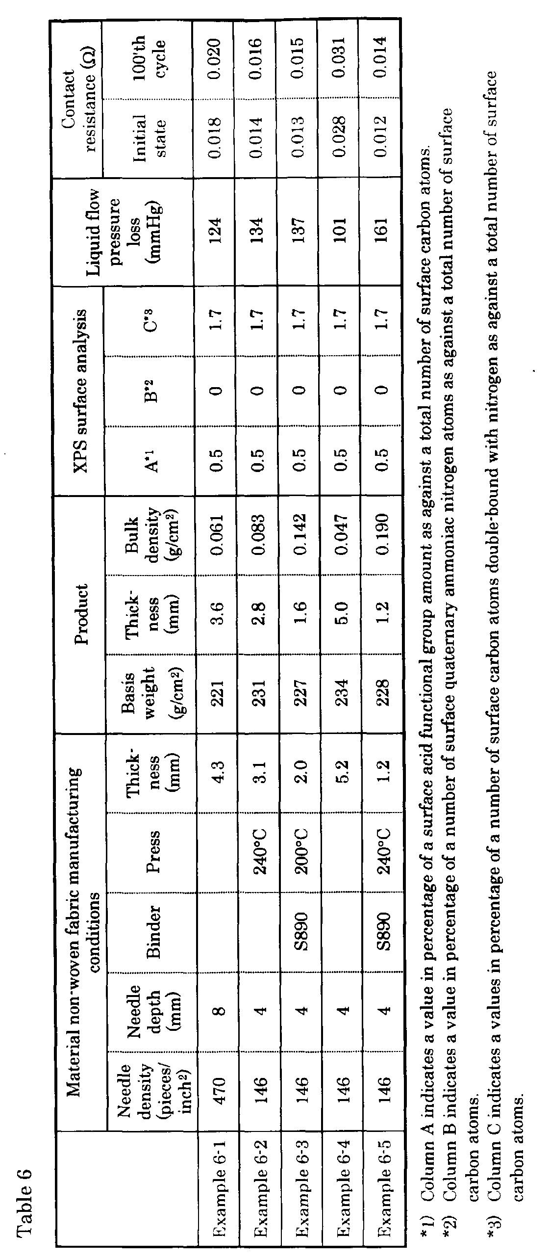
- a non-woven fabric according to the present invention has a bulk density of 0.05 - 0.17 g/cm 3 , more preferably 0.055 - 0.165 g/cm 3 .
- the bulk density is less than 0.05 g/cm 3 , the liquid flow pressure loss tends to decrease but, when the cell is mounted, the compression stress is decreased, so that the cell resistance tends to rise.
- the bulk density exceeds 0.17 g/cm 3 , on the other hand, the liquid flow pressure loss tend to rise to increase the liquid delivery pump loss, thus deteriorating the total battery efficiency.
- a needle punching method is employed as a pre-stage, to obtain the above-mentioned predetermined bulk density, such s property as relating to the bulk density of the carbonaceous fiber non-woven fabric must be optimized including conditions of the needle punching method for non-woven fabrics such as the properties, needle density, needle depth, and pressing gap for needle punching needles while forming non-weaving the fabric.
- the needle punching method for non-woven fabrics such as the properties, needle density, needle depth, and pressing gap for needle punching needles while forming non-weaving the fabric.
- thermal pressing can be conducted or thermal crimping can be conducted under the presence of a binder.
- a method is employed as to enhance the density of needle punching needles, but preferably, when thermal pressing or thermal crimping by use of a binder is conducted, needle punching is performed with such a needle density as to hold the shape of the non-woven fabric and then thermal pressing or thermal crimping by use of a binder is performed.
- the temperature and the pressure When conducting thermal pressing, although the temperature and the pressure must be adjusted depending on the properties of each fiber, generally, preferably it is conducted at a pressing temperature of 100 - 240°C and a cotton pressure of 6 - 60 kg/cm 2 .
- a binder although it may come in various types such as acrylic type, starch type, polyvinyl alcohol type, epoxy resin type, vinyl acetate type, phenol resin type, etc. without limits, in order to maintain adhesive-ness even after carbonization, most preferably a phenol resin-based binder is used.
- the method for adding the binder to a non-woven fabric may come in a method of adding it during fiber mixing after a raw fiber material is opened, a method of solving or scattering it into an organic solvent and attaching it to a non-woven fabric to dry it, and a method of scattering a powder binder into the air and attaching it to the non-woven fabric surface, it is not limited to these but only needs to be conducted under appropriate conditions for each material.
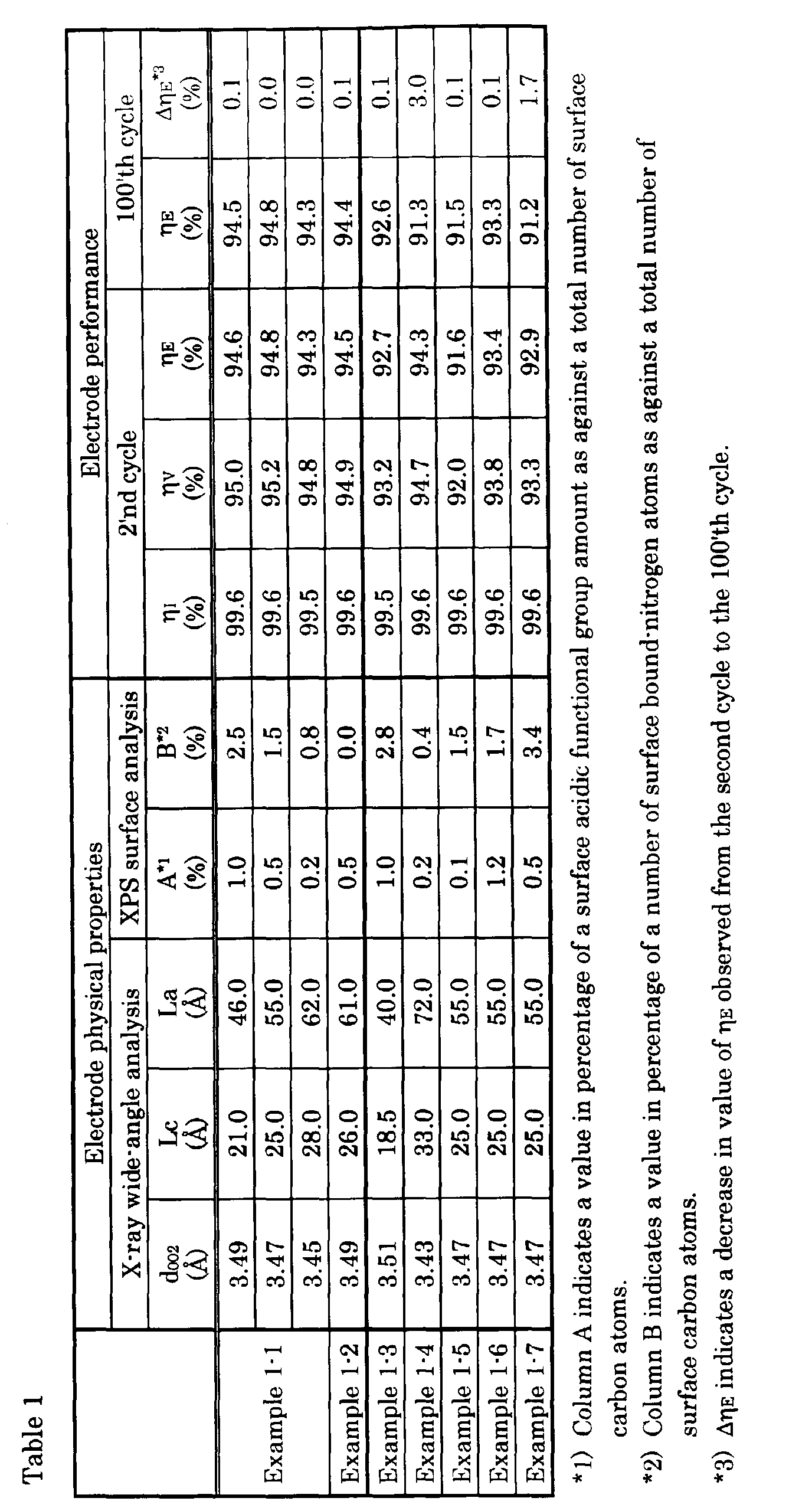
- various methods of measuring a ⁇ 002 ⁇ inter-facial spacing (d002), a c-axial crystallite size (Lc), an a-axial crystallite size (La), XPS surface analysis, a current efficiency, a voltage efficiency (cell resistance R), and time-wise changes in the energy efficiency after the charge-discharge cycles.
- An electrode material is crushed to about a particle diameter of 10 ⁇ m in an agate mortar, to mix as an internal standard substance an about 5-weight% of X-ray standard high-purity silicon power against a specimen and put it into a cell, to measure an wide-angle X-ray with a diffraction meter method using CuK ⁇ ray as a ray source.
- a curve is corrected not in terms of so-called the Lorenz factor, the polarization factor, the absorption factor, the atom-scattering factor, etc. but done so using a following simple method. That is, from a base-line of a peak which corresponds to a ⁇ 002 ⁇ diffraction, an effective strength is re-plotted, to obtain a ⁇ 002 ⁇ corrected strength curve.
- Lc k1 ⁇ ⁇ Cos ⁇ ( ⁇ ) where the wavelength ⁇ is 1.54148 ⁇ , the structure coefficient k1 is 0.9, ⁇ indicates the ⁇ 002 ⁇ diffraction angle, and ⁇ indicates a hall-value of the ⁇ 002 ⁇ diffraction peak.
- an effective strength is re-plotted from the base-line of a peak which corresponds to the ⁇ 10 ⁇ diffraction, to obtain a corrected strength curve.
- the a-axial crystallite size La is obtained using Equation 3.
- La k2 ⁇ ⁇ Cos ⁇ ( ⁇ ) where the wavelength ⁇ is 1.5418 ⁇ , the structure coefficient k2 is 1.84, ⁇ indicates the ⁇ 10 ⁇ diffraction angle, and ⁇ indicates the half-width of the ⁇ 10 ⁇ diffraction peak.
- ESCA X-ray photo-electronic spectroscopy
- XPS X-ray photo-electronic spectroscopy
- Each specimen is immersed in an acetone solution of silver nitrate, to completely replace the proton of the acid functional groups with silver, clean it with acetone and water respectively, blank it into pieces with a 6-mm diameter, and adhere it to a heating specimen table for analysis by conducting paste.
- the specimen Beforehand, prior to measurement, the specimen is heated to 120°C and removed of air in vacuum for three hours or longer.
- an MgK ⁇ -ray 1253.6eV
- the intra-apparatus vacuum degree is 10 -7 torr.
- N/C ratio The number of surface bound-nitrogen atoms as against a total number of surface carbon atoms (N/C ratio) is obtained in percentage (%) as a ratio of (number of surface nitrogen atoms/number of surface carbon atoms) and the surface acid functional group amount as against a total number of surface carbon atoms, as a ratio of (number of surface silver atoms/number of surface carbon atoms).
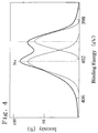
- an N1s peak is separated into peaks of 400.1eV and 402.5eV, to decide a peak area, as quaternary nitrogen, of peaks appearing at 402.5eV, thus calculating in percentage (%) the area ratio as against the whole surface carbon.
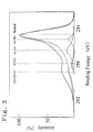
- FIG. 3 shows an example where a measured C1s peak was separated for each of its bonding structure
- FIG. 4 shows an example where the N1s peak was separated for each of its bonding structure.
- As the positive-electrode electrolyte solution 3 mol/l of sulfuric-acid aqueous solution of 2 mol/l vanadium oxysulfate was used and as the negative-electrode electrolyte solution, 3 mol/l of sulfuric-acid aqueous solution of 2 mol/l vanadium sulfate was used.
- the amount of the electrolyte solutions is set largely excessive as against the cell and the piping.
- a flow rate of the liquid is set at 6.2 ml/m, for measurement at 30°C. Note here that the viscosity of the above-mentioned electrolyte solutions at 25°C was 0.006Pa ⁇ s for the positive electrode and 0.0 1Pa ⁇ s for the negative electrode.
- the properties of electrodes for an electrolytic cell used in redox-flow type batteries etc. are represented by the above-mentioned current efficiency ⁇ I , the voltage efficiency ⁇ V (cell resistance R), and the energy efficiency ⁇ E (product of ⁇ I and ⁇ V ) as well as their charge-discharge stability values (service lives) during charge-discharge cycles.
- the current efficiency ⁇ I is decreased because a charged amount is partially dissipated due to side reactions such as generation of hydrogen or oxygen mainly during charging.
- each of the elements has each electrochemical reaction selectivity.
- different crystallinities of carbon also have correspond to different electron energy levels, which have a large influence on the electrochemical reaction selectivity, i.e. current efficiency ⁇ I.
- the present invention makes it possible to remarkably enhance the current efficiency ⁇ I providing the above-mentioned carbon structure.
- a short fiber of the flame-resistant fiber (length; about 80 mm) was felted to make a non-woven fabric having basis weight of 400 g/m 2 and the thickness of 4.0 mm. While an argon gas was constantly blasted to the non-woven fabric at 600 cc/min./m 2 , a temperature was raised to 1400°C, 1600°C or 1800°C, respectively, at a temperature raising rate of 100°C/min. and a temperature was maintained at the each temperature for 1 hour to perform carbonization. Thereafter, the non-woven fabric was cooled, and treated in the nitrogen gas atmosphere having the oxygen concentration of 7% at 700°C to yield by weight of 95% to obtain three kinds of carbonaceous fibrous non-woven fabrics.
- a short fiber of the infusible fiber (length; about 80 mm) was felted to make a non-woven fabric having basis weight of 500 g/m 2 and the thickness of 5.5 mm. While an argon gas was constantly blasted to the non-woven fabric at 600 cc/min./m 2 , a temperature was raised to 1200°C at a temperature raising rate of 100°C/min, and a temperature was maintained at that temperature for 1 hour to perform carbonization. Thereafter, the non-woven fabric was cooled, and treated in the nitrogen gas atmosphere having the oxygen concentration of 7% at 700°C to yield by weight of 95% to obtain the carbonaceous fibrous non-woven fabric.
- a non-woven fabric made under the same conditions as those of Example 1-1 was heated to 1400°C at a temperature raising rate of 10°C/min, in the nirogen gas atmosphere, maintained at that temperature for 1 hour to perform carbonization, cooled, and treated in the nitrogen gas atmosphere having the oxygen concentration of 7% at 700°C to yield by weight of 95% to obtain the carbonaceous fibrous non-woven fabric.
- Example 1-1 While an argon gas was constantly blasted to a non-woven fabric made under the same conditions as those of Example 1-1 at 600 cc/min./m 2 , it was heated to 2000°C at a temperature raising rate of 100°C/min., maintained at that temperature for 1 hour to perform carbonization, cooled, and treated in the nitrogen gas atmosphere having the oxygen concentration of 7% at 700°C to yield by weight of 95% to obtain the carbonaceous fibrous non-woven fabric.
- Example 1-1 While an argon gas was constantly blasted to a non-woven fabric made under the same conditions as those of Example 1-1 at 600 cc/min./m 2 , it was heated to 1600°C at a temperature raising rate of 100°C/min., maintained at that temperature for 1 hour to perform carbonization, cooled, and treated in the nitrogen gas atmosphere having the oxygen concentration of 0.5% at 700°C to yield by weight of 95% to obtain the carbonaceous fibrous non-woven fabric.
- Example 1-1 While an argon gas was constantly blasted to a non-woven fabric made under the same conditions as those of Example 1-1 at 600 cc/min./m 2 , it was heated to 1600°C at a temperature raising rate of 100°C/min., maintained at that temperature for 1 hour to perform carbonization, cooled, and treated in an air at 700°C to yield by weight of 85% to obtain the carbonaceous fibrous non-woven fabric.
- Example 1-1 While a nitrogen gas was constantly blasted to a non-woven fabric made under the same conditions as those of Example 1-1 at 600 cc/min./m 2 , it was heated to 1600°C at a temperature raising rate of 100°C/min., maintained at that temperature for 1 hour to perform carbonization, cooled, and treated in the nitrogen gas atomosphere having the oxygen concentration of 7% to yield by weight of 95% at 900°C to obtain the carbonaceous fibrous non-woven fabric.
- a polyacrylonitrile fiber having the average fiber diameter of 16 ⁇ m was converted into flame-resistant at 200 to 300°C in an air, a short fiber(length; about 80 mm) of the flame-resistant fiber was felted to make a non-woven fabric having basis weight of 400 g/m 2 and the thickness of 4.0 mm.
- the non-woven fabric was soaked in a 0.01 wt% aqueous bismuth hydroxide solution, dehydraded (0.008 wt% attachment in terms of bismuth ion), heated to 2000°C in the nitrogen gas at a temperature raising rate of 10°C/min., maintained at that temperature for 1 hour to perform carbonization, cooled, and oxidizing-treated to yield by weight of 93% at 650°C in an air to obtain the carbonaceous fibrous non-woven fabric.
- a non-woven fabric made under the same conditions as those of Example 2-1 was soaked in a 0.01 wt% aluminum hydroxide solution, dehydraded (0.06 wt% attachment in terms of aluminum ion), heated to 1600°C at a temperature raising rate of 10°C/min. in the nitrogen gas, maintained at this temperature for 1 hour to perform carbonization, cooled, and oxidizing-treated to yield by weight of 93% at 650° C in an air to obtain the carbonaceous fiburous non-woven fabric.
- a non-woven fabric made under the same conditions as those of Example 2-1 was heated to 130°C at a temperature raising rate of 10°C/min. in the nitrogen gas, maintain at this temperature for 1 hour to perform carbonization, cooled, and oxidizing-treated to yield by weight of 93% at 650°C in an air to obtain the carbonaceous fibrous non-woven fabric.
- a non-woven fabric made under the same conditions as those of Example 2-1 was heated to 2000°C at a temperature raising rate of 10°C/min. in the nitrogen gas, maintained at this temperature for 1 hour to perform carbonization, cooled, and oxidizing-treated to yield by weight of 93% at 650°C in an air to obtain the carbonaceous fibrous non-woven fabric.
- a polyacrylonitrile fiber of the average fiber diameter of 16 ⁇ m was converted into flame-resistant in an air at 200 to 300°C, a short fiber (length; about 80 mm) of the flame-resistant fiber was felted to make a non-woven fabric having basis weight of 400 g/m 2 and the thickness of 4.0 mm. While an argon gas was constantly blasted to the non-woven fabric at 600 cc/min./m 2 , the non-woven fabric was heated to 1600°C at a temperature raising rate of 100°C/min., maintained at this temperature for 1 hour to perform carbonization, cooled, and treated to yield by weight of 93% at 700°C in the nitrogen stream of the oxygen concentration of 0.5 vol%. Further, non-woven fabric was activated at 500°C for 10 minutes in the nitrogen stream containing 20 vol% water steam to obtain the carbonaceous fibrous non-woven fabric.
- Example 3-1 While an argon gas was constantly blasted to a non-woven fabric made under the same conditions as those of Example 3-1 at 600 cc/min./m 2 , the non-woven fabric was heated to 1600°C at a temperature raising rate of 100°C/min., maintained at this temperature for 1 hour to perform carbonization, cooled, and treated to yield by weight of 93% at 700°C under the nitrogen stream having the oxygen concentration of 0.5 vol%. Further, the non-woven fabric was activated at 200°C for 5 minutes under the nitrogen stream containing 5 vol% hydrogen chloride gas and 20 vol% water steam to obtain the carbonaceous fibrous non-woven fabric.
- a non-woven fabric made under the same conditions as those of Example 3-1 was heated to 1200°C at a temperature raising rate of 10°C/min. in the nitrogen gas, maintained at this temperature for 1 hour to perform carbonization, cooled, and treated to yield by weight of 93% at 700°C under the nitrogen stream having the oxygen concentration of 7 vol% to obtain the carbonaceous fibrous non-woven fabric.
- Example 3-1 While an argon gas was constantly blasted to a non-woven fabric made under the same conditions as those of Example 3-1 at 600 cc/min./m 2 , heated to 2000°C at a temperature raising rate of 10°C/min., maintained at this temperature for 1 hour to perform carbonization, cooled, and treated to yield by weight of 93% at 700°C under the nitrogen stream having the oxygen concentration of 7 vol%. Further, the non-woven fabric was activated at 500°C for 10 minutes under the nitrogen stream containing 20 vol% water stream to obtain the carbonaceous fibrous non-woven fabric.
- Example 3-1 While an argon gas was constantly basted to a non-woven fabric made under the same conditions as those of Example 3-1 at 600 cc/min./m 2 , the non-woven fabric was heated to 1600°C at a temperature raising rate of 10°C/min., maintained at this temperature for 1 hour to perform carbonization, cooled, and treated to yield by weight of 93% at 700°C under the nitrogen gas atomosphere having the oxygen concentration of 0.5 vol%. Further, the non-woven fabric was activated at 200°C for 5 minutes under the nitrogen stream containing 5vol% hydrogen chloride gas and 20 vol% water steam to obtain the carbonaceous fibrous non-woven fabric.
- Initial contact resistance was measured by cutting a sample into 1 cm ⁇ 10 cm size, compressing the sample to the predetermined spacer thickness with two conducting plates from the thickness direction using a teflon spacer having the thickness of 2.5 mm and measuring the resistances at both size of the conducting plate with digital multimeter (TR6846 manufactured by Advantest).
- contact resistance after 100 cycles was measured by making a small cell having an electrode area 10 cm 2 of 1 cm in an up and down direction (solution flow direction) and 10 cm in a width direction, repeating 100 cycles charge and discharge at constant current density, after completion, washing a sample used for a cathode, drying, and measuring contact resistance according an initial contact resistance measuring method.
- Example 3-1 0.5 0.0 1.7 0.025 0.027
- Example 3-2 0.8 0.6 1.8 0.026 0.029
- Example 3-3 1.2 0.0 3.3 0.026 0.035
- Example 3-4 0.3 0.0 0.1 0.025 0.036
- Example 3-5 2.1 1.2 1.8 0.033 0.045
- a polyacrylonitrile fiber having the average fabric diameter of 16 ⁇ m was converted into flame-resistant in an air at 200 to 300°C, a short fiber (length; about 80mm) of the flame-resistant fiber was felted to make a non-woven fabric having basis weight of 400 g/m 2 and the thickness of 4.0 mm.
- the non-woven fabric was heated to 1200°C at a temperature raising rate of 100°C/min. under the nitrogen stream, maintained at this temperature for 1 hour to perform carbonization, cooled, and treated to yield by weight of 93% at 700°C in an air to obtain the carbonaceous fibrous non-woven fabric.
- This sample was placed in an argon gas atomospheric furnace containing 15 vol% hydrogen gas, heated at a temperature raising rate of 600°C/h, heat-treated for 5 minutes, and cooled gradually to obtain a reduced-type carbonaceous fibrous non -woven fabric.
- a non-woven fabric made under the same conditions as those of Example 4-1 was heated to 1400°C at a temperature raising rate of 100°C/min. under the nitrogen stream, maintained at this temperature for 1 hour to perform carbonization, cooled, and treated to yield by weight of 93% at 550°C in an air to obtain the carbonaceous fibrous non-woven fabric.
- Example 4-2 A sample made in Example 4-2 was placed into an argon gas atomospheric furnace containing 15 vol% hydrogen gas, heated at a temperature raising rate of 600°C/h, heat-treated at 700°C for 5 minutes, and cooled gradually to obtain a reduced-type carbonaceous fibrous non-woven fabric.
- a non-woven fabric made under the same conditions as those of Example 4-1 was heated to 1200°C at a temperature raising rate of 100°C/min. under the nitrogen stream, maintained at this temperature for 1 hour to perform carbonization, cooled, and treated to yield by weight of 98% at 700°C in an air to obtain the carbonaceous fibrous non-woven fabric.
- a polyacrylonitrile fiber composed of acrylonitrile 98 mole%-methyl methacrylate 2 mole%, having weight average molecular weight of 75000 and average fiber diameter of 16 ⁇ m was converted into flame-resistant in an air at 200 to 300°C, and a short fiber (length; about 80 mm) of the flame-resistant fiber was felted with a felting needle SB#36 (Foster Needle Company) at a punching density of 250/cm 2 to make a non-woven fabric having basis weight of 600 g/m 2 and the thickness of 5.0 mm.
- a felting needle SB#36 Froster Needle Company
- the non-woven fabric was heated to 1400°C at a temperature raising rate of 100°C/min., maintained at this temperature for 1 hour to perform carbonization, cooled, and treated by stretching with 0.1 kgf/cm width tension at 700°C in an air to yield by weight of 93% to obtain the carbonaceous fibrous non-woven fabric.
- a polyacrylonitrile fiber composed of acrylonitrile 97 mole%-vinyl acetate 3 mole%, having weight average molecular weight of 200000 and average fiber diameter of 16 ⁇ m was converted into flame-resistant in an air at 200 to 300 °C. According to the same manner as that of Example 5-1 except that a short fiber (length; about 80 mm) of this flame-resistant fiber was used, a non-woven fabric was made and treated to obtain the carbonaceous fibrous non-woven fabric.
- Example 5-1 According to the same manner as that of Example 5-1 except that a punching density was 150/cm 2 , a carbonaceous fibrous non-woven fabric was obtained.
- Example 5-1 According to the same manner as that of Example 5-1 except that a punching density was 350/cm 2 , a carbonaceous fibrous non-woven fabric was obtained.
- Example 5-1 According to the same manner as that of Example 5-1 except that a non-woven fabric was treated to yield by weight of 93% at 700°C in an air without applying tension, a carbonaceous fibrous non-woven fabric was obtained.
- a resin binding graphite plate (thickness;3 mm) having specific resistance of 0.05 ⁇ cm was used for the current collecting plate, and resistance when the current collecting plates are mutually contacted by pressure can be negligible compared with the contact resistance with the non-woven fabric.
- a polyacrylonitrile having the average fiber diameter of 16 ⁇ m was converted into flame-resistant in an air at 200 to 300°C, and cut into about 80 mm in length to make a short fiber of a flame-resistant fiber.
- This was made into a non-woven fabric under the conditions of a needle of #HDB40 manufactured by Foster Company, needle density of 470/inch 2 , depth of 8 mm and pushing gap of 4 mm to make a non-woven fabric having basis weight of 400 g/m 2 and the thickness of 4.3 mm. Then, the non-woven fabric was heated to 1200°C at a temperature raising rate of 100°C/min.
- the non-woven fabric was placed into an argon gas atomospheric furnace containing 15vol% hydrogen gas, heated at a temperature raising rate of 600°C/h, heat-treated at 700°C for 5 minutes, cooled gradually to obtain a reduced-type carbonaceous fibrous non-woven fiber.
- a polyacrylonitrile fiber having the average fiber diameter of 16 ⁇ m was converted into flame-resistant in an air at 200 to 300°C, and cut into about 80mm in length to make a short fiber of a flame-resistant fiber.
- This was made into a non-woven fabric under the conditions of a needle of #HDB40 manufactured by Foster Company, needle density of 146/inch 2 , depth of 4 mm and pushing gap of 4 mm to make a non-woven fabric having basis weight of 400 g/m 2 and the thickness of 5.2 mm. Then, the non-woven fabric was passed through a calendar roll at line pressure of 60 kg/cm to press to the thickness of 3.1 mm. The non-woven fabric was heated to 1200°C at a temperature raising rate of 100°C/min.
- the non-woven fabric was placed into an argon gas atomospheric furnace containing 15 vol% hydrogen gas, heated at a temperature raising rate of 600°C/h, heat-treated at 700°C for 5 minutes, and cooled gradually to obtain a reduced-type carbonaceous fibrous non-woven fabric.
- a polyacrylonitrile fiber having the average fiber diameter of 16 ⁇ m was converted into flame-resistant in an air at 200 to 300°C, and cut into 80 mm in length to make a short fiber of a flame-resistant fiber.
- phenol resin powder trade name Bellpearl S890, manufactured by Kanebo (K.K.)
- Kanebo K.K.
- the non-woven fabric was passed through a calendar roll at line pressure of 60 kg/cm and 200°C to press to the thickness of 2.0 mm.
- the non-woven fabric was heated to 1200°C at a temperature raising rate of 100°C/min. under the nitrogen stream, maintained at this temperature for 1 hour to perform carbonization, cooled, and treated to yield by weight of 93% at 700°C in an air.
- the non-woven fabric was placed into an argon gas atomospheric furnace containing 15 vol% hydrogen gas, heated at a temperature raising rate of 600°C/h, and heat-treated at 700°C for 5 minutes, and cooled gradually to obtain a reduced-type carbonaceous fibrous non-woven fabric.
- Example 6-2 According to the same manner as that of Example 6-2 except that a non-woven fabric was not pressed by passing through a calendar roll at line pressure of 60 kg/cm and 240°C, a reduced-type carbonaceous fibrous non-woven fabric was obtained.
- Example 6-2 According to the same manner as that of Example 6-2 except that a short fiber was made into a non-woven fabric by adding 0.5% by weight of phenol resin powder (trade name Bellpearl S890, manufactured by Kanebo (K.K.)), relative to the weight of the flame-resistant fiber, a reduced-type carbonaceous fibrous fabric was obtained.
- phenol resin powder trade name Bellpearl S890, manufactured by Kanebo (K.K.)
- Liquid flow pressure loss was measured as follows: a liquid flowing-type electrolysis tank, composed of 20 cm in a liquid flow direction, 10 cm in width direction (path width) and a 1.2 mm spacer, having the same shape as that of a liquid flowing-type electrolysis tank was prepared, and an electrode material made (carbonaceous fibrous non-woven fabric) was cut into 10 cm x 10 cm and arranged.
- Ion-exchanged water was flown at a liquid amount of 5 liter/h and liquid flow pressure losses between outlet and inlet of an electrolysis tank were measured. The similar measurement was carried out without arrangement of the electrode material as a blank and a difference between the measured value and the blank measured value was adopted as solution conducting pressure loss of an electrode material.
Landscapes
- Chemical & Material Sciences (AREA)
- Chemical Kinetics & Catalysis (AREA)
- Electrochemistry (AREA)
- General Chemical & Material Sciences (AREA)
- Life Sciences & Earth Sciences (AREA)
- Organic Chemistry (AREA)
- Geology (AREA)
- Inorganic Chemistry (AREA)
- General Life Sciences & Earth Sciences (AREA)
- Engineering & Computer Science (AREA)
- Manufacturing & Machinery (AREA)
- Sustainable Development (AREA)
- Sustainable Energy (AREA)
- Inert Electrodes (AREA)
- Fuel Cell (AREA)
Abstract
Description
Similarly, it is assumed that different crystallinities of carbon also have correspond to different electron energy levels, which have a large influence on the electrochemical reaction selectivity, i.e. current efficiency ηI. The present invention makes it possible to remarkably enhance the current efficiency ηI providing the above-mentioned carbon structure. This is assumed because the reaction selectivity based on an electron energy level of a carbon material having the above-mentioned structure is in an optimal state in a system used and also, the carbon's internal structure is made uniform (averaged) and the structural defects etc. are reduced or eliminated, thus making the electrode potential uniform. Note here that as publicly known, metal impurities, especially such transition metals as iron, chromium, and nickel act as a catalyst for promoting the side reaction, so that it is preferable to use such a carbon material that contains those impurities as less as possible.

| XPS surface analysis value | Contact resistance (Ω) | ||||
| Initial state | 100'th cycle | ||||
| Example 3-1 | 0.5 | 0.0 | 1.7 | 0.025 | 0.027 |
| Example 3-2 | 0.8 | 0.6 | 1.8 | 0.026 | 0.029 |
| Example 3-3 | 1.2 | 0.0 | 3.3 | 0.026 | 0.035 |
| Example 3-4 | 0.3 | 0.0 | 0.1 | 0.025 | 0.036 |
| Example 3-5 | 2.1 | 1.2 | 1.8 | 0.033 | 0.045 |
| XPS surface analysis value | Contact resistance (Ω) | |||
| Initial state | 100'th cycle | |||
| Example 4-1 | 0.8 | 88.0 | 0.026 | 0.027 |
| Example 4-2 | 0.8 | 77.0 | 0.039 | 0.048 |
| Example 4-3 | 0.4 | 82.0 | 0.025 | 0.027 |
| Example 4-4 | 0.3 | 98.0 | 0.023 | 0.045 |

Claims (13)
- A carbon electrode material for a vanadium-based redox-flow type battery, comprising quasi-graphite crystal structure, wherein 〈002〉 spacing is 3.43 to 3.60 Å, size of a crystallite in c axial direction is 15 to 33 Å, and size of a crystallite in a axial direction is 30 to 70 Å, each obtained by X-ray wide angle analysis,and having surface property obtained by XPS surface analysis wherein an amount of surface acidic functional groups is 0.1 to 1.2% relative to total number of surface carbon atoms and number of surface bound-nitrogen atoms is 5% or smaller relative to total number of surface carbon atoms.
- The carbon electrode material according to claim 1, wherein said amount of surface acidic functional groups is 0.2 to 1.0% relative to total number of surface carbon atoms and said number of surface bound-nitrogen atoms is 3% or smaller relative to total number of surface carbon atoms.
- The carbon electrode material according to claim 1 or 2, wherein said 〈002〉 spacing is 3.45 to 3.50 Å, said size of a crystallite in c axial direction is 20 to 30 Å and said size of a crystallite in a axial direction is 45 to 65 Å.
- The carbon electrode material according to any one of claims 1 to 3, wherein a half value half width of a peak at 1360 cm-1 is 30 to 60 cm-1, a half value half width of a peak at 1580 cm-1 is 30 to 45 cm-1, and a ratio R of peak intensity Ia at 1360 cm-1 and peak intensity Ig at 1580 cm-1 (= Ia/Ig) is 0.7 to 1.0 each obtained by a laser Raman spectroscopic method.
- The carbon electrode material according to claims 1 to 3, wherein a stacked structure ratio based on a peak intensity of 〈002〉 diffraction obtained by X-ray wide angle analysis is 0.50 to 0.90.
- The carbon electrode material according to claims 1 to 3, wherein number of surface carbon atoms which are double-bound with nitrogen obtained by XPS surface analysis is 0.3 to 3.0% relative to total number of surface carbon atoms.
- The carbon electrode material according to claim 6, wherein number of surface quaternary ammonium nitrogen atoms obtained by XPS surface analysis is 1.0% or smaller relative to total number of surface carbon atoms.
- The carbon electrode material according to claims 1 to 3, wherein number of surface neutral carbon atoms obtained by XPS surface analysis is 80 to 95% relative to total number of surface carbon atoms.
- The carbon electrode material according to claims 1 to 8, wherein the viscosity of an electrolysis solution of the battery is 0.005 Pa·s or greater at 25°C.
- The carbon electrode material according to claims 1 to 8, wherein an electrolysis solution of the battery contains vanadium ion at an amount of 1.5 mol/l.
- The carbon electrode material according to claims 1 to 10, wherein the carbon electrode material is formed into a non-woven fabric of a carbonaceous fiber, the non-woven fabric has compressibility of 10 to 25% and compression modulus of 80% or greater each obtained according to JIS L1096 (1990).
- The carbon electrode material according to claims 1 to 10, wherein the carbon electrode material is formed into a non-woven fabric of a carbonaceous fiber and the non-woven fabric has bulk density of 0.05 to 0.17 g/cm3.
- The carbon electrode material according to claim 11 or 12, said non-woven fabric has one or more concave groove formed on one face thereof.
Applications Claiming Priority (2)
| Application Number | Priority Date | Filing Date | Title |
|---|---|---|---|
| JP16549899A JP3601581B2 (en) | 1999-06-11 | 1999-06-11 | Carbon electrode material for vanadium redox flow battery |
| JP16549899 | 1999-06-11 |
Publications (3)
| Publication Number | Publication Date |
|---|---|
| EP1059685A2 true EP1059685A2 (en) | 2000-12-13 |
| EP1059685A3 EP1059685A3 (en) | 2002-02-27 |
| EP1059685B1 EP1059685B1 (en) | 2004-05-06 |
Family
ID=15813547
Family Applications (1)
| Application Number | Title | Priority Date | Filing Date |
|---|---|---|---|
| EP00112205A Expired - Lifetime EP1059685B1 (en) | 1999-06-11 | 2000-06-07 | Use of a carbon electrode material for vanadium-based redox-flow type battery |
Country Status (6)
| Country | Link |
|---|---|
| US (1) | US6509119B1 (en) |
| EP (1) | EP1059685B1 (en) |
| JP (1) | JP3601581B2 (en) |
| AT (1) | ATE266260T1 (en) |
| AU (1) | AU767205B2 (en) |
| DE (1) | DE60010372T2 (en) |
Cited By (7)
| Publication number | Priority date | Publication date | Assignee | Title |
|---|---|---|---|---|
| WO2006070945A3 (en) * | 2004-12-28 | 2007-02-15 | Ebara Corp | Chemically modified organic polymeric material, and method and apparatus for manufacturing the same |
| EP1411575A4 (en) * | 2001-06-12 | 2009-09-23 | Sumitomo Electric Industries | CELL STACK FOR A REDOX FLOW CELL |
| EP2003718A4 (en) * | 2006-03-29 | 2009-11-25 | Cataler Corp | ELECTROCONDUCTIVE CARBON SUPPORT FOR FUEL CELL, ELECTRODE CATALYST FOR FUEL CELL, AND SOLID POLYMER ELECTROLYTE FUEL CELL COMPRISING SAME |
| EP2626936A1 (en) * | 2012-02-09 | 2013-08-14 | EWE-Forschungszentrum Für Energietechnologie E.V. | Activation of carbon electrodes by means of plasma treatment |
| CN107710479A (en) * | 2015-07-09 | 2018-02-16 | 住友电气工业株式会社 | Redox flow batteries electrode and redox flow battery system |
| CN110036513A (en) * | 2016-12-01 | 2019-07-19 | 东丽株式会社 | Electrode and redox flow batteries |
| EP3680975A4 (en) * | 2017-09-07 | 2021-06-02 | Toyobo Co., Ltd. | CARBON ELECTRODE MATERIAL FOR REDOX BATTERY AND ASSOCIATED MANUFACTURING PROCESS |
Families Citing this family (91)
| Publication number | Priority date | Publication date | Assignee | Title |
|---|---|---|---|---|
| KR101496934B1 (en) | 2006-11-15 | 2015-03-03 | 유니버시티 오브 워싱톤 스루 이츠 센터 포 커머셜리제이션 | electric double layer capacitance device |
| US7855005B2 (en) * | 2007-02-12 | 2010-12-21 | Deeya Energy, Inc. | Apparatus and methods of determination of state of charge in a redox flow battery |
| US8587150B2 (en) * | 2008-02-28 | 2013-11-19 | Deeya Energy, Inc. | Method and modular system for charging a battery |
| US7927731B2 (en) * | 2008-07-01 | 2011-04-19 | Deeya Energy, Inc. | Redox flow cell |
| US8785023B2 (en) * | 2008-07-07 | 2014-07-22 | Enervault Corparation | Cascade redox flow battery systems |
| US7820321B2 (en) * | 2008-07-07 | 2010-10-26 | Enervault Corporation | Redox flow battery system for distributed energy storage |
| US20100092843A1 (en) * | 2008-10-10 | 2010-04-15 | Deeya Energy Technologies, Inc. | Venturi pumping system in a hydrogen gas circulation of a flow battery |
| CN102246338B (en) * | 2008-10-10 | 2014-06-11 | 迪亚能源股份有限公司 | Thermal control of a flow cell battery |
| US8231993B2 (en) * | 2008-10-10 | 2012-07-31 | Deeya Energy, Inc. | Flexible multi-walled tubing assembly |
| WO2010042900A1 (en) * | 2008-10-10 | 2010-04-15 | Deeya Energy Technologies, Inc. | Methods for bonding porous flexible membranes using solvent |
| US8236463B2 (en) * | 2008-10-10 | 2012-08-07 | Deeya Energy, Inc. | Magnetic current collector |
| US8230736B2 (en) * | 2008-10-10 | 2012-07-31 | Deeya Energy, Inc. | Level sensor for conductive liquids |
| EP2351184A4 (en) * | 2008-10-10 | 2014-07-09 | Deeya Energy Technologies Inc | Method and apparatus for determining state of charge of a battery |
| WO2010064556A1 (en) | 2008-12-02 | 2010-06-10 | 日清紡ホールディングス株式会社 | Carbon catalyst, method for manufacturing the carbon catalyst, and electrode and battery using the carbon catalyst |
| WO2010064555A1 (en) * | 2008-12-02 | 2010-06-10 | 日清紡ホールディングス株式会社 | Carbon catalyst, method for manufacturing the carbon catalyst, and electrode and battery using the carbon catalyst |
| EP2436080A2 (en) * | 2009-05-28 | 2012-04-04 | Deeya Energy, Inc. | Electrolyte compositions |
| CN102460811B (en) * | 2009-05-28 | 2015-11-25 | 艾默吉电力系统股份有限公司 | Redox flow cell rebalancing |
| CN102460812B (en) * | 2009-05-28 | 2014-12-31 | 艾默吉电力系统股份有限公司 | Preparation of flow battery electrolytes from raw materials |
| US8723489B2 (en) * | 2009-05-28 | 2014-05-13 | Deeya Energy, Inc. | Bi-directional buck-boost circuit |
| US20110079074A1 (en) * | 2009-05-28 | 2011-04-07 | Saroj Kumar Sahu | Hydrogen chlorine level detector |
| US8349477B2 (en) * | 2009-05-28 | 2013-01-08 | Deeya Energy, Inc. | Optical leak detection sensor |
| US8587255B2 (en) * | 2009-05-28 | 2013-11-19 | Deeya Energy, Inc. | Control system for a flow cell battery |
| US8551299B2 (en) * | 2009-05-29 | 2013-10-08 | Deeya Energy, Inc. | Methods of producing hydrochloric acid from hydrogen gas and chlorine gas |
| CN105226284B (en) | 2009-07-01 | 2017-11-28 | 巴斯夫欧洲公司 | Ultrapure synthetic carbon materials |
| US8443922B2 (en) | 2009-10-07 | 2013-05-21 | The Boeing Company | Containment device and method for containing energy storage devices |
| US8951665B2 (en) * | 2010-03-10 | 2015-02-10 | Imergy Power Systems, Inc. | Methods for the preparation of electrolytes for chromium-iron redox flow batteries |
| KR101067867B1 (en) | 2010-04-14 | 2011-09-27 | 전자부품연구원 | Integrated graphite / DSA electrode for redox flow battery, manufacturing method thereof and redox flow battery comprising same |
| US9281535B2 (en) | 2010-08-12 | 2016-03-08 | Imergy Power Systems, Inc. | System dongle |
| CN103429283B (en) * | 2010-08-13 | 2015-11-25 | 日本协能电子股份有限公司 | Liquid leakage detection system |
| KR101861212B1 (en) * | 2010-09-09 | 2018-06-29 | 캘리포니아 인스티튜트 오브 테크놀로지 | Electrochemical Energy Storage Systems and Methods |
| WO2012045002A1 (en) | 2010-09-30 | 2012-04-05 | Energ2 Technologies, Inc. | Enhanced packing of energy storage particles |
| CN103339762B (en) | 2011-01-13 | 2016-03-30 | 伊莫基动力系统公司 | Flow cell stack |
| CN102136579B (en) * | 2011-01-30 | 2013-06-26 | 国网电力科学研究院武汉南瑞有限责任公司 | Modified method of graphite felt used for full-vanadium fluid flow battery electrode |
| US8980484B2 (en) | 2011-03-29 | 2015-03-17 | Enervault Corporation | Monitoring electrolyte concentrations in redox flow battery systems |
| US8916281B2 (en) | 2011-03-29 | 2014-12-23 | Enervault Corporation | Rebalancing electrolytes in redox flow battery systems |
| US20120262127A1 (en) | 2011-04-15 | 2012-10-18 | Energ2 Technologies, Inc. | Flow ultracapacitor |
| CN103947017B (en) | 2011-06-03 | 2017-11-17 | 巴斯福股份公司 | Carbon-lead blends for use in hybrid energy storage devices |
| CN102867967B (en) * | 2011-07-05 | 2015-08-19 | 中国科学院大连化学物理研究所 | A kind of all-vanadium liquid flow energy storage battery electrode material and application thereof |
| WO2013120011A1 (en) | 2012-02-09 | 2013-08-15 | Energ2 Technologies, Inc. | Preparation of polymeric resins and carbon materials |
| DE102012016317A1 (en) | 2012-08-14 | 2014-02-20 | Jenabatteries GmbH | Redox flow cell for storing electrical energy |
| US9685651B2 (en) | 2012-09-05 | 2017-06-20 | Ess Tech, Inc. | Internally manifolded flow cell for an all-iron hybrid flow battery |
| US9614244B2 (en) | 2012-09-05 | 2017-04-04 | Ess Tech, Inc. | Redox and plating electrode systems for an all-iron hybrid flow battery |
| CN110112377A (en) | 2013-03-14 | 2019-08-09 | 14族科技公司 | The complex carbon material of electrochemical modification agent comprising lithium alloyage |
| CN205752372U (en) * | 2013-03-15 | 2016-11-30 | 格拉弗技术国际控股有限公司 | Components of electrode bipolar plates for flow batteries |
| WO2014145844A1 (en) * | 2013-03-15 | 2014-09-18 | Unienergy Technologies, Llc | Systems and methods for shunt current and mechanical loss mitigation in electrochemical systems |
| KR102364280B1 (en) | 2013-09-25 | 2022-02-16 | 록히드 마틴 에너지, 엘엘씨 | Electrolyte balancing strategies for flow batteries |
| TWI501455B (en) * | 2013-10-28 | 2015-09-21 | Inst Nuclear Energy Res Atomic Energy Council | Method of Fabricating Electrode for High-Power-Density Flow Cell |
| CN103531827B (en) * | 2013-10-31 | 2015-10-14 | 大连交通大学 | A kind of method improving electrochemical activity of graphite felt of positive electrode of flow battery |
| US10195583B2 (en) | 2013-11-05 | 2019-02-05 | Group 14 Technologies, Inc. | Carbon-based compositions with highly efficient volumetric gas sorption |
| US10230124B2 (en) * | 2013-12-03 | 2019-03-12 | Massachusetts Institute Of Technology | Gravity induced flow cell |
| KR102663138B1 (en) | 2014-03-14 | 2024-05-03 | 그룹14 테크놀로지스, 인코포레이티드 | Novel methods for sol-gel polymerization in absence of solvent and creation of tunable carbon structure from same |
| JP6340070B2 (en) * | 2014-04-11 | 2018-06-06 | 昭和電工株式会社 | Redox flow battery |
| EP3284129B1 (en) | 2015-04-14 | 2020-09-16 | Lockheed Martin Energy, LLC | Flow battery balancing cells having a bipolar membrane for simultaneous modification of a negative electrolyte solution and a positive electrolyte solution |
| EP3284130B1 (en) | 2015-04-14 | 2024-09-11 | Lockheed Martin Energy, LLC | Flow battery balancing cells having a bipolar membrane and methods for use thereof |
| DE102015212234A1 (en) | 2015-06-30 | 2017-01-26 | Sgl Carbon Se | Process for producing carbon felt electrodes for redox flow batteries |
| JP6786776B2 (en) * | 2015-07-28 | 2020-11-18 | 東洋紡株式会社 | Manufacturing method of electrode material for redox batteries |
| JP2017027920A (en) * | 2015-07-28 | 2017-02-02 | 東洋紡株式会社 | Redox battery electrode material |
| JP2017027918A (en) * | 2015-07-28 | 2017-02-02 | 東洋紡株式会社 | Redox flow battery electrode material |
| JP6973075B2 (en) * | 2015-07-31 | 2021-11-24 | 東洋紡株式会社 | Carbon electrode material for redox batteries |
| JP2017033757A (en) * | 2015-07-31 | 2017-02-09 | 東洋紡株式会社 | Carbon electrode material for redox batteries |
| US20190097222A1 (en) | 2015-08-14 | 2019-03-28 | Energ2 Technologies, Inc. | Composites of porous nano-featured silicon materials and carbon materials |
| CN119419246A (en) | 2015-08-28 | 2025-02-11 | 14集团技术公司 | New materials with extremely durable lithium intercalation and methods for making them |
| KR20180069911A (en) * | 2015-11-13 | 2018-06-25 | 아발론 배터리 (캐나다) 코포레이션 | Improved electrode for redox flow battery |
| JP6671719B2 (en) * | 2015-11-16 | 2020-03-25 | アイシン精機株式会社 | Gas diffusion electrode material for biofuel cell, method for producing gas diffusion electrode material, biofuel cell provided with gas diffusion electrode material |
| US10340528B2 (en) | 2015-12-02 | 2019-07-02 | California Institute Of Technology | Three-dimensional ion transport networks and current collectors for electrochemical cells |
| TWI552424B (en) * | 2016-02-01 | 2016-10-01 | 台灣奈米碳素股份有限公司 | Method for manufacturing a nitrogen contained carbon electrode and a flow battery using it |
| JP6819982B2 (en) | 2016-02-26 | 2021-01-27 | 日清紡ホールディングス株式会社 | Carbon catalyst for redox flow battery electrodes |
| JP6729889B2 (en) * | 2016-02-26 | 2020-07-29 | 日清紡ホールディングス株式会社 | Carbon catalyst for redox flow battery electrodes |
| US10347925B2 (en) | 2016-04-29 | 2019-07-09 | Lockheed Martin Energy, Llc | Three-chamber electrochemical balancing cells for simultaneous modification of state of charge and acidity within a flow battery |
| JP6809257B2 (en) * | 2017-01-31 | 2021-01-06 | 東洋紡株式会社 | Carbon material and batteries using it |
| KR102127037B1 (en) | 2017-02-28 | 2020-06-25 | 주식회사 엘지화학 | Electrode structure and redox flow battery comprising the same |
| EP3593369A4 (en) | 2017-03-09 | 2021-03-03 | Group14 Technologies, Inc. | DECOMPOSITION OF SILICON-CONTAINING PRECURSORS ON POROUS FRAMEWORK MATERIALS |
| US10461352B2 (en) | 2017-03-21 | 2019-10-29 | Lockheed Martin Energy, Llc | Concentration management in flow battery systems using an electrochemical balancing cell |
| US11342572B2 (en) * | 2017-08-09 | 2022-05-24 | Sumitomo Electric Industries, Ltd. | Redox flow battery |
| WO2019049755A1 (en) * | 2017-09-07 | 2019-03-14 | 東洋紡株式会社 | Carbon electrode material for redox flow battery, and method for manufacturing carbon electrode material |
| JP7126415B2 (en) * | 2018-03-14 | 2022-08-26 | 日鉄ケミカル&マテリアル株式会社 | Microbial fuel cells and anode carbon electrodes for wastewater treatment |
| KR102142886B1 (en) * | 2018-11-19 | 2020-08-10 | (주)코멕스카본 | Processing method of porous carbon electrode and porous carbon electrode thereof |
| KR102328721B1 (en) * | 2018-12-17 | 2021-11-18 | 한국전자기술연구원 | Surface treated carbon material electrode, its surface treatment method and zinc-bromide toxic flow secondary cell having the same |
| CN113544887A (en) | 2019-03-13 | 2021-10-22 | 东洋纺株式会社 | Carbon electrode material for redox flow battery and redox flow battery having the same |
| WO2021009929A1 (en) | 2019-07-18 | 2021-01-21 | 住友電気工業株式会社 | Redox-flow battery cell, cell stack, and redox-flow battery system |
| WO2021009928A1 (en) * | 2019-07-18 | 2021-01-21 | 住友電気工業株式会社 | Redox flow battery cell, cell stack and redox flow battery system |
| JP2023537954A (en) | 2020-08-10 | 2023-09-06 | グループ14・テクノロジーズ・インコーポレイテッド | vibration heat assisted chemical vapor infiltration |
| US11335903B2 (en) | 2020-08-18 | 2022-05-17 | Group14 Technologies, Inc. | Highly efficient manufacturing of silicon-carbon composites materials comprising ultra low z |
| US11174167B1 (en) | 2020-08-18 | 2021-11-16 | Group14 Technologies, Inc. | Silicon carbon composites comprising ultra low Z |
| EP4146595A1 (en) | 2020-08-18 | 2023-03-15 | Group14 Technologies, Inc. | Manufacturing of silicon-carbon composites materials |
| US11639292B2 (en) | 2020-08-18 | 2023-05-02 | Group14 Technologies, Inc. | Particulate composite materials |
| CN116457309B (en) | 2020-09-30 | 2025-02-14 | 14集团技术公司 | Passivation method to control oxygen content and reactivity of silicon-carbon composites |
| EP4462522A4 (en) * | 2022-01-06 | 2025-11-26 | Sumitomo Electric Industries | ELECTRODE, BATTERY CELL, CELL STACK AND REDOX FLOW BATTERY SYSTEM |
| EP4523270A4 (en) | 2022-05-09 | 2026-04-22 | Lockheed Martin Energy Llc | RIVER BATTERY WITH A DYNAMIC FLUID NETWORK |
| US20260038854A1 (en) * | 2022-08-16 | 2026-02-05 | Sumitomo Electric Industries, Ltd. | Redox-flow battery system |
| CN115275226B (en) * | 2022-09-02 | 2023-04-11 | 寰泰储能科技股份有限公司 | Electrode preparation method, electrode and flow battery |
Family Cites Families (20)
| Publication number | Priority date | Publication date | Assignee | Title |
|---|---|---|---|---|
| JPS59119680A (en) * | 1982-12-27 | 1984-07-10 | Toyobo Co Ltd | Electrode for flow type electrolytic cell |
| JPS61225325A (en) * | 1985-03-23 | 1986-10-07 | Asahi Chem Ind Co Ltd | Carbonaceous fiber |
| US4816289A (en) | 1984-04-25 | 1989-03-28 | Asahi Kasei Kogyo Kabushiki Kaisha | Process for production of a carbon filament |
| JPS60232669A (en) | 1984-05-02 | 1985-11-19 | Toyobo Co Ltd | Electrode materials for electrolytic cells |
| JPH0690933B2 (en) * | 1984-05-30 | 1994-11-14 | 東洋紡績株式会社 | Stacked electrolytic cell |
| JPS63203870A (en) * | 1987-02-12 | 1988-08-23 | 旭化成株式会社 | Acidic group-containing carbonaceous fiber |
| JPS63211326A (en) * | 1987-02-20 | 1988-09-02 | Toray Ind Inc | Graphite fiber having high compression strength |
| KR950007819B1 (en) * | 1988-12-26 | 1995-07-20 | 도오레 가부시기가이샤 | Acrylic Carbon Fiber and Manufacturing Method Thereof |
| JP2955938B2 (en) * | 1989-04-20 | 1999-10-04 | 東洋紡績株式会社 | Carbon-based electrode materials for electrolytic cells |
| US5209975A (en) * | 1989-10-30 | 1993-05-11 | Tonen Kabushiki Kaisha | High elongation, high strength pitch-type carbon fiber |
| JPH0543763A (en) * | 1990-12-07 | 1993-02-23 | Osaka Gas Co Ltd | Fluorocarbon resin composition |
| JPH05234612A (en) * | 1992-02-21 | 1993-09-10 | Toyobo Co Ltd | Carbon electrode material for electrolytic cell |
| JPH087913A (en) * | 1994-06-22 | 1996-01-12 | Kashima Kita Kyodo Hatsuden Kk | Full vanadium redox cell |
| JP3496385B2 (en) * | 1995-02-16 | 2004-02-09 | 住友電気工業株式会社 | Redox battery |
| JP3560181B2 (en) | 1995-04-13 | 2004-09-02 | 東洋紡績株式会社 | Electrode material for liquid flow type electrolytic cell |
| JPH09223513A (en) * | 1996-02-19 | 1997-08-26 | Kashimakita Kyodo Hatsuden Kk | Liquid circulation battery |
| JPH10125345A (en) * | 1996-10-23 | 1998-05-15 | Taiyo Koukou Kk | Manufacture of vanadium electrolyte |
| JPH10245213A (en) * | 1997-03-05 | 1998-09-14 | Tatsuya Shono | Production of hydrophilic carbonaceous material |
| JPH1167257A (en) * | 1997-08-19 | 1999-03-09 | Kashimakita Kyodo Hatsuden Kk | Process for vanadium electrolyte |
| JPH11260377A (en) | 1998-03-12 | 1999-09-24 | Toyobo Co Ltd | Carbon electrode material and its manufacture |
-
1999
- 1999-06-11 JP JP16549899A patent/JP3601581B2/en not_active Expired - Fee Related
-
2000
- 2000-06-06 AU AU37947/00A patent/AU767205B2/en not_active Ceased
- 2000-06-07 DE DE60010372T patent/DE60010372T2/en not_active Expired - Lifetime
- 2000-06-07 AT AT00112205T patent/ATE266260T1/en active
- 2000-06-07 EP EP00112205A patent/EP1059685B1/en not_active Expired - Lifetime
- 2000-06-08 US US09/590,629 patent/US6509119B1/en not_active Expired - Lifetime
Cited By (11)
| Publication number | Priority date | Publication date | Assignee | Title |
|---|---|---|---|---|
| EP1411575A4 (en) * | 2001-06-12 | 2009-09-23 | Sumitomo Electric Industries | CELL STACK FOR A REDOX FLOW CELL |
| US9017869B2 (en) | 2001-06-12 | 2015-04-28 | Sumitomo Electric Industries, Ltd. | Cell stack for redox flow battery |
| WO2006070945A3 (en) * | 2004-12-28 | 2007-02-15 | Ebara Corp | Chemically modified organic polymeric material, and method and apparatus for manufacturing the same |
| EP2003718A4 (en) * | 2006-03-29 | 2009-11-25 | Cataler Corp | ELECTROCONDUCTIVE CARBON SUPPORT FOR FUEL CELL, ELECTRODE CATALYST FOR FUEL CELL, AND SOLID POLYMER ELECTROLYTE FUEL CELL COMPRISING SAME |
| US8372562B2 (en) | 2006-03-29 | 2013-02-12 | Cataler Corporation | Conductive carbon carrier for fuel cell, electrode catalyst for fuel cell and solid polymer fuel cell comprising same |
| CN104037430A (en) * | 2006-03-29 | 2014-09-10 | 株式会社科特拉 | Conductive Carbon Carrier for Fuel Cell, Electrode Catalyst for Fuel Cell and Solid Polymer Fuel Cell Comprising Same |
| EP2626936A1 (en) * | 2012-02-09 | 2013-08-14 | EWE-Forschungszentrum Für Energietechnologie E.V. | Activation of carbon electrodes by means of plasma treatment |
| CN107710479A (en) * | 2015-07-09 | 2018-02-16 | 住友电气工业株式会社 | Redox flow batteries electrode and redox flow battery system |
| EP3322011A4 (en) * | 2015-07-09 | 2018-06-06 | Sumitomo Electric Industries, Ltd. | Electrode for redox flow battery, and redox flow battery system |
| CN110036513A (en) * | 2016-12-01 | 2019-07-19 | 东丽株式会社 | Electrode and redox flow batteries |
| EP3680975A4 (en) * | 2017-09-07 | 2021-06-02 | Toyobo Co., Ltd. | CARBON ELECTRODE MATERIAL FOR REDOX BATTERY AND ASSOCIATED MANUFACTURING PROCESS |
Also Published As
| Publication number | Publication date |
|---|---|
| AU767205B2 (en) | 2003-11-06 |
| JP3601581B2 (en) | 2004-12-15 |
| EP1059685B1 (en) | 2004-05-06 |
| ATE266260T1 (en) | 2004-05-15 |
| JP2000357520A (en) | 2000-12-26 |
| DE60010372T2 (en) | 2005-05-04 |
| AU3794700A (en) | 2000-12-14 |
| US6509119B1 (en) | 2003-01-21 |
| EP1059685A3 (en) | 2002-02-27 |
| DE60010372D1 (en) | 2004-06-09 |
Similar Documents
| Publication | Publication Date | Title |
|---|---|---|
| EP1059685B1 (en) | Use of a carbon electrode material for vanadium-based redox-flow type battery | |
| JP6617464B2 (en) | Carbon electrode material for redox batteries | |
| EP3680975A1 (en) | Carbon electrode material for redox flow battery, and manufacturing method thereof | |
| US20220153591A1 (en) | Carbon electrode material for manganese/titanium-based redox flow battery | |
| JP2017027919A (en) | Redox battery electrode material | |
| JP6973075B2 (en) | Carbon electrode material for redox batteries | |
| JPWO2019049755A1 (en) | Carbon electrode material for redox flow battery and method for producing the same | |
| JP2017027918A (en) | Redox flow battery electrode material | |
| JP2017033757A (en) | Carbon electrode material for redox batteries | |
| JP6809257B2 (en) | Carbon material and batteries using it | |
| JPH02281564A (en) | Carbon electrode material for electrolytic bath | |
| CN113544888B (en) | Carbon Electrode Materials and Redox Batteries | |
| EP3940830A1 (en) | Carbon electrode material and redox battery | |
| JP4366802B2 (en) | Carbon electrode material assembly and manufacturing method thereof | |
| JP2001085028A (en) | Carbon electrode material assembly | |
| JP2001085022A (en) | Carbon electrode material and carbon electrode material assembly | |
| EP3940829A1 (en) | Carbon electrode material for redox flow battery and redox flow battery provided with same | |
| JP3589285B2 (en) | Carbon electrode material for redox flow batteries | |
| JP2020149858A (en) | Positive electrode material for redox battery and redox battery including the same | |
| JP2001085025A (en) | Carbon electrode material assembly | |
| JP2001085026A (en) | Carbon electrode material assembly | |
| JP2001085021A (en) | Carbon electrode material assembly | |
| WO2021225107A1 (en) | Carbon electrode material for manganese/titanium-based redox flow battery | |
| JP2000357523A (en) | Carbon electrode material for redox flow battery | |
| JP2001085024A (en) | Carbon electrode material assembly |
Legal Events
| Date | Code | Title | Description |
|---|---|---|---|
| PUAI | Public reference made under article 153(3) epc to a published international application that has entered the european phase |
Free format text: ORIGINAL CODE: 0009012 |
|
| AK | Designated contracting states |
Kind code of ref document: A2 Designated state(s): AT DE GB IT SE Kind code of ref document: A2 Designated state(s): AT BE CH CY DE DK ES FI FR GB GR IE IT LI LU MC NL PT SE |
|
| AX | Request for extension of the european patent |
Free format text: AL;LT;LV;MK;RO;SI |
|
| PUAL | Search report despatched |
Free format text: ORIGINAL CODE: 0009013 |
|
| AK | Designated contracting states |
Kind code of ref document: A3 Designated state(s): AT BE CH CY DE DK ES FI FR GB GR IE IT LI LU MC NL PT SE |
|
| AX | Request for extension of the european patent |
Free format text: AL;LT;LV;MK;RO;SI |
|
| 17P | Request for examination filed |
Effective date: 20020403 |
|
| 17Q | First examination report despatched |
Effective date: 20020717 |
|
| AKX | Designation fees paid |
Free format text: AT DE GB IT SE |
|
| GRAP | Despatch of communication of intention to grant a patent |
Free format text: ORIGINAL CODE: EPIDOSNIGR1 |
|
| RTI1 | Title (correction) |
Free format text: USE OF A CARBON ELECTRODE MATERIAL FOR VANADIUM-BASED REDOX-FLOW TYPE BATTERY |
|
| RTI1 | Title (correction) |
Free format text: USE OF A CARBON ELECTRODE MATERIAL FOR VANADIUM-BASED REDOX-FLOW TYPE BATTERY |
|
| GRAS | Grant fee paid |
Free format text: ORIGINAL CODE: EPIDOSNIGR3 |
|
| GRAA | (expected) grant |
Free format text: ORIGINAL CODE: 0009210 |
|
| AK | Designated contracting states |
Kind code of ref document: B1 Designated state(s): AT DE GB IT SE |
|
| REG | Reference to a national code |
Ref country code: GB Ref legal event code: FG4D |
|
| REF | Corresponds to: |
Ref document number: 60010372 Country of ref document: DE Date of ref document: 20040609 Kind code of ref document: P |
|
| REG | Reference to a national code |
Ref country code: IE Ref legal event code: FG4D |
|
| REG | Reference to a national code |
Ref country code: SE Ref legal event code: TRGR |
|
| REG | Reference to a national code |
Ref country code: IE Ref legal event code: MM4A |
|
| PLBE | No opposition filed within time limit |
Free format text: ORIGINAL CODE: 0009261 |
|
| STAA | Information on the status of an ep patent application or granted ep patent |
Free format text: STATUS: NO OPPOSITION FILED WITHIN TIME LIMIT |
|
| 26N | No opposition filed |
Effective date: 20050208 |
|
| PGFP | Annual fee paid to national office [announced via postgrant information from national office to epo] |
Ref country code: GB Payment date: 20140604 Year of fee payment: 15 |
|
| PGFP | Annual fee paid to national office [announced via postgrant information from national office to epo] |
Ref country code: SE Payment date: 20140611 Year of fee payment: 15 |
|
| REG | Reference to a national code |
Ref country code: SE Ref legal event code: EUG |
|
| GBPC | Gb: european patent ceased through non-payment of renewal fee |
Effective date: 20150607 |
|
| PG25 | Lapsed in a contracting state [announced via postgrant information from national office to epo] |
Ref country code: SE Free format text: LAPSE BECAUSE OF NON-PAYMENT OF DUE FEES Effective date: 20150608 |
|
| PG25 | Lapsed in a contracting state [announced via postgrant information from national office to epo] |
Ref country code: GB Free format text: LAPSE BECAUSE OF NON-PAYMENT OF DUE FEES Effective date: 20150607 |
|
| PGFP | Annual fee paid to national office [announced via postgrant information from national office to epo] |
Ref country code: AT Payment date: 20160525 Year of fee payment: 17 |
|
| PGFP | Annual fee paid to national office [announced via postgrant information from national office to epo] |
Ref country code: IT Payment date: 20160621 Year of fee payment: 17 |
|
| REG | Reference to a national code |
Ref country code: AT Ref legal event code: MM01 Ref document number: 266260 Country of ref document: AT Kind code of ref document: T Effective date: 20170607 |
|
| PG25 | Lapsed in a contracting state [announced via postgrant information from national office to epo] |
Ref country code: AT Free format text: LAPSE BECAUSE OF NON-PAYMENT OF DUE FEES Effective date: 20170607 Ref country code: IT Free format text: LAPSE BECAUSE OF NON-PAYMENT OF DUE FEES Effective date: 20170607 |
|
| PGFP | Annual fee paid to national office [announced via postgrant information from national office to epo] |
Ref country code: DE Payment date: 20190528 Year of fee payment: 20 |
|
| REG | Reference to a national code |
Ref country code: DE Ref legal event code: R071 Ref document number: 60010372 Country of ref document: DE |