EP1059613B1 - Reflexionslinienkontrolle - Google Patents
Reflexionslinienkontrolle Download PDFInfo
- Publication number
- EP1059613B1 EP1059613B1 EP00401395A EP00401395A EP1059613B1 EP 1059613 B1 EP1059613 B1 EP 1059613B1 EP 00401395 A EP00401395 A EP 00401395A EP 00401395 A EP00401395 A EP 00401395A EP 1059613 B1 EP1059613 B1 EP 1059613B1
- Authority
- EP
- European Patent Office
- Prior art keywords
- reflection line
- shape
- new
- vector
- reflection
- Prior art date
- Legal status (The legal status is an assumption and is not a legal conclusion. Google has not performed a legal analysis and makes no representation as to the accuracy of the status listed.)
- Expired - Lifetime
Links
Images


Classifications
-
- G—PHYSICS
- G06—COMPUTING OR CALCULATING; COUNTING
- G06T—IMAGE DATA PROCESSING OR GENERATION, IN GENERAL
- G06T15/00—3D [Three Dimensional] image rendering
- G06T15/50—Lighting effects
-
- Y—GENERAL TAGGING OF NEW TECHNOLOGICAL DEVELOPMENTS; GENERAL TAGGING OF CROSS-SECTIONAL TECHNOLOGIES SPANNING OVER SEVERAL SECTIONS OF THE IPC; TECHNICAL SUBJECTS COVERED BY FORMER USPC CROSS-REFERENCE ART COLLECTIONS [XRACs] AND DIGESTS
- Y10—TECHNICAL SUBJECTS COVERED BY FORMER USPC
- Y10S—TECHNICAL SUBJECTS COVERED BY FORMER USPC CROSS-REFERENCE ART COLLECTIONS [XRACs] AND DIGESTS
- Y10S715/00—Data processing: presentation processing of document, operator interface processing, and screen saver display processing
- Y10S715/961—Operator interface with visual structure or function dictated by intended use
- Y10S715/964—CAD or CAM, e.g. interactive design tools
Definitions
- the present invention relates generally to computer-aided design (CAD), manufacturing (CAM) and engineering (CAE), and product data management (PDM II) systems and to a system and method for controlling the shape of reflection lines on the surface of an object in such CAD, CAM, CAE or PDM II systems. More particularly, the present invention provides for direct control of the reflection line and the modification of the shape of an object to correspond to a desired reflection line on the surface of the object.
- CAD computer-aided design
- CAM manufacturing
- CAE engineering
- PDM II product data management
- CAD systems are widely used for many types of design and manufacturing applications. Certain of these applications can be very costly in terms of user interaction time.
- One such interaction intensive application is object or surface design and modification.
- the external appearance of the product plays a major role.
- the car industry provides a good example of this well-known fact.
- One significant aspect of the external appearance of the product is the way in which its surface reflects the light in the room where the product is presented to prospective buyers. This can be a car dealer showroom where neon tubes provide most of the light in the room and the prospective buyers see the reflection of the neon light as reflection lines on the external surface of the cars. It has been shown that smooth reflection lines tend to leave the consumer with a better impression of the product than erratic or misshapen reflection lines.
- the surface of the object being designed is displayed to the user with a simulation of the reflection of a light source, say an elongated neon light source, system allows the user to alter the shape of the surface by means of free-form surface shape design techniques. Then the new reflection line is shown to the user and the process is repeated until the user is reasonably satisfied with what appears on the computer. In this process the user has no direct control over the reflection line: for the software functionalities the reflection line is only a "by-product" of the shape of the surface, whereas in many cases it is the ultimate goal of the user. This is a long and tedious trial-and-error process. There is a need for a system which would allow the user to define up front the reflection line the surface should preferably exhibit and which would then reshape the surface to attain or approximate this kind of reflection line.
- a light source say an elongated neon light source
- a further method for surface modification is described in an article titled Direct Highlight Line Modification on NURBS Surfaces, by Chen et al., Computer Aided Geometric Design 14 (1997) 583-601.
- This article describes a method for modifying a surface using highlight lines.
- the highlight lines differ from reflection lines in that they are viewer independent, i.e., not based on any viewer perspective, and are not subject to change based on a viewer's perspective.
- highlight lines are simpler to implement than reflection lines, but do not provide a realistic model for surface design or modification.
- the article entitled Modeling of surfaces with fair reflection line pattern by Loos J. et al. describes a method for enabling the designer to control, during the modeling process, the reflection line pattern by approximating a specified family of reflection lines. In this approach, the viewer and light source are located at infinity.
- the present invention solves these problems and provides an apparatus and method for modifying the shape of an object, for example, a surface, by using reflection lines, while at the same time maintaining certain constraints on the object being modified.
- an object may be modified based on a realistic viewer perspective.
- the present invention provides an apparatus and method for modifying the shape of an object, for example, a surface, by defining the shape and/or position of one or more lines along which a light source is reflected by the object (reflection line). Based upon a change, such as, for example, the position and/or shape, to one or more of the reflection lines, the system modifies the shape of the object to correspond to the new surface requirements as defined by one or more of the modified reflection lines, while maintaining the constraint on the object as predetermined by the system or user.
- the light source may be any type of light source, such as, for example, a linear neon or fluorescent light, or a curved neon or fluorescent light.
- the apparatus utilizes a CAD system, and provides for control of the reflection line using a control device, for example, a cursor control device, such as a mouse, a roller ball, a pressure pad, or a capacitance or inductance based pad, or for example, an interactive display device, such as a light pen, or a touch screen.
- a control device for example, a cursor control device, such as a mouse, a roller ball, a pressure pad, or a capacitance or inductance based pad, or for example, an interactive display device, such as a light pen, or a touch screen.
- the apparatus includes a processor programmed to determine the shape of the object, for example, a surface or a set of adjacent surfaces, based on either one or more selected reflection lines.
- the processor can be programmed to use energy minimization algorithms to make these determinations.
- the processor may also be programmed to determine one or more reflection lines approximating one or more desired reflection lines, which are merely targets for the actual reflection lines, based on an attraction to one or more of the desired reflection lines. This may be implemented using vector-to-vector springs.
- a user By defining one or more reflection lines, a user is effectively and indirectly controlling the shaping of an object by the system. This is useful for all types of object design activities, including, for example, surface design used in aircraft (for example, for critical air flow requirements), auto body design (for example, for aesthetic requirements) and bottle design (for example, perfume bottles).
- the reflection line is set by the user or reset from a current setting to a defined setting and the system shapes (in the case of a flat or initial surface) or modifies the shape of the surface to correspond to the defined setting, with the defined setting becoming the new setting of the reflection line and the system determined shape or system modified shape becoming the new shape of the surface.
- the reflection line and corresponding surface may be modified absolutely, i.e., by imposing on the surface that it include a user input curve as a reflection line, or they may be modified by attraction, i.e., by considering the user input curve to be a target to which the reflection line on the surface is pulled by a force or loading.
- Each approach has certain advantages and disadvantages. Absolute modification instantly guarantees that the surface will exhibit the desired reflection line. However, by imposing such a strong constraint on this line, the surface can generate undesirable characteristics in other areas, because the system may become overconstrained. Modification by attraction in most cases yields better surface behavior because the reflection line is allowed to deviate slightly from the target in order to avoid an overconstrained condition.
- Modification of a surface may be accomplished by user control of the reflection line.
- the system adjusts the surface to correspond to the new reflection line as defined by the user.
- the system determines the normal vectors to an imaginary surface, based on a predetermined linear light source and observer, which would correspond to the defined reflection line.
- the system then adjusts the surface to correspond to the determined normal vectors representing the imaginary surface.
- the preferred strategy is to select a shape based on energy minimization.
- the adjustment of the surface to correspond to the determined normal vectors may be accomplished by a vector to vector spring load.
- a method utilizing energy minimization determines a new shape for the surface based on the lowest change in energy from the shape being modified, such as, for example, an initial flat plane or a previous design.
- This energy may be defined, for example, as a sum of the integral of stretch and of bending of the surface.
- the system, apparatus and method according to the present invention may be implemented, for example, as computer readable program code and may be contained in or on, or placed into or onto a computer usable medium, such as, for example, a CD ROM, hard drive, computer disc, computer tape, optical storage medium, magnetic storage medium, electronic storage medium, chemical storage medium, EEPROM, RAM, or any other medium now known or which may become known in the future.
- a computer usable medium such as, for example, a CD ROM, hard drive, computer disc, computer tape, optical storage medium, magnetic storage medium, electronic storage medium, chemical storage medium, EEPROM, RAM, or any other medium now known or which may become known in the future.
- the system, apparatus and method according to the present invention may also be implemented as a computer program product, such as, for example, a computer file or files, for use with a graphic display or some other display device, such as, for example, a printer or plotter, holographic display, or virtual reality display device, having computer readable program code which can be stored in or on an electrical, magnetic, chemical, optical, mechanical or audio storage medium or any other storage medium now know or which hereinafter becomes known.
- a computer program product such as, for example, a computer file or files, for use with a graphic display or some other display device, such as, for example, a printer or plotter, holographic display, or virtual reality display device, having computer readable program code which can be stored in or on an electrical, magnetic, chemical, optical, mechanical or audio storage medium or any other storage medium now know or which hereinafter becomes known.
- the system, apparatus and method according to the present invention may also be transferred via hard copy, electronic transfer, such as, for example, via the internet, intranet, WAN, LAN, email, or via any other medium, such as, for example, any of the media previously described herein, or as a computer data signal embodied in a data stream, such as, for example, a digital, analog or optical data stream.
- FIG. 1 there is shown a diagram of a reflection of a point source off a shaped surface.
- Light beam 1 originates from a point source 3 and reflects on a surface 5 at a reflection point 7.
- a normal vector 13 is defined by the surface 5 at reflection point 7, which bisects the angle formed by the light beam 1 and the reflected light beam 9 in direction 11.
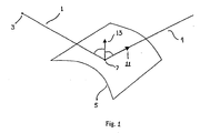
- FIG. 2 a diagram of a reflection line of a linear light source 15 and a reflection of a light beam 18 from point 16 of the linear light source 15 off the surface 5 at reflection point 7.
- the reflection of a linear light source 15, for example, a neon tube, on the surface 5 creates a reflection line 17 as seen by an observer 19.
- For each point on the reflection line 17 on surface 5 there is a point on the linear light source 15 such that the reflected light beam 20 will be seen by the observer 19 after reflection.
- the bisector of the angle formed by the light beam 18 and the reflected light beam 20 is the normal vector 21 to the surface 5 at reflection point 7.
- the reflection line 17 is the image of the linear light source 15 on the surface 5, as seen by the observer 19.
- FIGs 3(a)-(d) there are shown diagrams depicting a reflection line control process according to an embodiment of the present invention.
- a reflection line 17 is shown which corresponds to the surface 5, the linear light source 15 and the observer 19.
- the surface 5 must be modified by the system such that the new reflection line as determined by the user represents a reflection line for the modified surface.
- a reflection line 17 for modification.
- a free-form curve 22 is generated on the surface 5 which is superimposed on the reflection line 17.
- Both the creation and a deformation of the free-form curve 22 can be accomplished using the tools available in most CAD software systems.
- free-form curve 22 can be a NURBS that can be deformed by moving its control points or by using an energy based deformation method.
- the user then interactively deforms the free-form curve 22 which becomes clearly distinguishable from the reflection line 17.
- the system modifies the shape of the surface 5 so that the new shape of the modified surface 25 generates a new reflection line 27 which corresponds to the new free-form curve 23.
- the new reflection line 27 becomes visually confused with the new free-form curve 23 as defined by the user.
- This method can be applied to a plurality of reflection lines corresponding to a plurality of linear light sources, or to a plurality of reflection lines as seen by an observer at a plurality of locations based on a single linear light source.
- the reflection line 17 is shown in Figure 3(c) as being distinguishable from the free-form curve 23, in many applications the processing capabilities are sufficiently powerful to modify the surface almost instantaneously such that the reflection line and the free-form curve always appear indistinguishable. Thus, the user may never see a gap between the two.
- Figures 4(a)-(b) show diagrams of a procedure for adjusting a shaped surface to match a user defined reflection line according to an embodiment of the present invention.
- a new free-form curve 23 is created.
- set A is defined as a set of points (M i ) on new free-form curve 23, obtained by discretizing new free-form curve 23.
- Points M i are defined as points from set A, and vectors n i are vectors normal to surface 5 at points M i .
- vectors n i are such that points M i are not reflection points of light beams between the linear light source 15 and the observer 19, for example, light beam 30, but rather are reflection points of light beams following different paths, for example, the path as shown by reflected light beam 32.
- new vectors m i are determined by the system such that points M i would be reflection points of light beams, for example, light beam 30, between the linear light source 15 and the observer 19, as shown for example, by reflected light beam 34, if the normal vectors to the surface 5 at points M i were vectors m i and not vectors n i .
- a new shape for the surface 5 is then determined by the system, for example, using an energy based deformation method (as described below), such that for all points M i belonging to A, the normal vectors to the new surface 25 at points M i will be vectors m;.
- the shape of the new surface 25 should be as close to the shape of surface 5 as possible while at the same time providing for the user defined modification to the reflection line.
- the angle between vector n i , the vector normal to the surface 5 at reflection point M i , as shown in Figure 4(a), and vector mi, the vector normal to new surface 25 at reflection point M i , as shown in Figure 4(b) must be small.
- FIG. 5 there is shown a diagram of a cross-section of the surface 5 depicting the normal vector 40 and the reflected light beam 36 prior to a modification of the surface 5 according to an embodiment of the present invention.
- the system determines a new vector 42 such that reflection point 38 would be a reflection point on new surface 25 if the normal vector to the new surface 25 at reflection point 38 was new vector 42 and not vector 40.
- set B is defined as the set of all vectors at a single reflection point, for example, reflection point 38 on the new reflection line 27 corresponding to new free-form curve 23, where each element of set B corresponds to a different point on a linear light source, for example, linear light source 15.
- New vector 42 is defined as the vector bisector of the angle formed between the point 33 on the linear light source, reflection point 38 and the observer 19. New vector 42 belongs to set B because a light beam 39 originating from point 33 and reflecting on surface 5 at reflection point 38 would continue on as reflected light beam 41 to the observer 19 if the normal vector at reflection point 38 was new vector 42. Thus, the system is able to select a vector m i from set B corresponding to any point on the linear light source 15.
- FIG. 6 there is shown a diagram of a plane upon which a point on the linear light source is selected for determining a normal vector for a deformation of a shaped surface according to an embodiment of the present invention.
- a preferred point 35 on linear light source 15 may be determined.
- a plane 37 is defined as intersecting the observer 19, reflection point 38 on the new free-form curve 23, and vector 40.
- the preferred point 35 is then defined as the intersection between plane 37 and linear light source 15.
- a corresponding preferred point on the linear light source 15 may be determined.
- FIG. 7 a diagram of a modification of the surface and a new normal vector for the modified surface according to an embodiment of the present invention.
- the normal vector to reflection point 38 on the new free-form curve 23 defined by the user was determined to be new vector 42.
- the system must determine a new shape for the surface 5 to correspond to the selection of all vectors m pi for all points on linear light source 15 based on the new free-form curve 23 defined by the user, such that the new reflection line 27 having normal vectors m pi will be superimposed on new free-form curve 23.
- there may be a displacement of each point M i due to the modification of the surface by the system such displacements are sufficiently small to allow satisfactory results despite not being taken into account as part of the system's determination.
- the advantage to this method is that the user has total control over the reflection line.
- Modification of a reflection line may be accomplished using a different method according to the present invention.
- Figure 8 there is shown a diagram of an attraction modification of the surface according to an embodiment of the present invention. The first few steps are similar to those described above with respect to the previous embodiment.
- a user selects a reflection line 17 to be modified, as described with respect to Figure 3(a).
- a free-form curve 22 is generated on the surface 5 which is superimposed on the reflection line 17, as described with respect to Figure 3(b).
- the free-form curve 22 is then modified by the user to create a new free-form curve 23, as described with respect to Figure 3(c).
- the system modifies the shape of the surface 5, using the method described below, such that the new surface 43 defines a new reflection line 45 which is not superimposed on the new free-form curve 23, but rather merely comes close to or approximates the new free-form curve 23.
- the reflection line is attracted to the free-form curve, allowing a user to interactively modify the shape of the reflection line by simply modifying the shape of the free-form curve.
- FIG. 9 there is shown a diagram of an attraction of a reflection line based on the selection by a user of a free-form curve.
- the system determines a new vector 42 for new free-form curve 23 such that reflection point 38 would be a reflection point if the normal vector to the surface 5 at reflection point 38 was new vector 42 and not vector 40.
- Set B is defined as the set of all such new vectors.
- New vector 42 is defined as the vector bisector of the angle formed between the preferred point 35, reflection point 38 on new free-form curve 23 and the observer 19.
- New vector 42 belongs to set B because a light beam 39 originating from preferred point 35 and reflecting on surface 5 at reflection point 38 on new free-form curve 23 would continue on as reflected light beam 41 to the observer 19 if the normal vector at reflection point 38 was new vector 42.
- the system is able to determine all vectors m pi for new free-form curve 23 corresponding to all points on the linear light source 15.
- the system determines "vector-to-vector" springs 50 attracting p i towards m pi for each i.
- An energy based deformation method is then used to determine a new shape for surface 5 such that each p i comes close to the corresponding m pi .
- the new reflection line 45 is not superimposed and visual indistinguishable from the new free-form curve 23, but instead approximates or is near to the new free-form curve 23.
- this method does not allow a user to select a definitive shape for the new reflection line, it does provide for an attraction or close approximation to such a shape. Moreover, because this method manages the minimization of both the internal energy of the surface and the energy of the springs, through the use of an energy based deformation method, and does not allow for any exact constraints on the normal vectors, it will produce a very smooth surface despite the constraints placed on the surface to be modified by the energy based deformation method.
- Reflection line control may be implemented using energy based deformation. This allows a user to deform a surface by making it behave like a physical material. Several types of constraints and loads may be defined, and the shape of the surface is determined by utilizing energy minimization algorithms.
- An energy based deformation method as utilized by the system allows a deformation of a surface while enforcing certain constraints, such as, for example, position, tangent or curvature constraints on points or curves of that surface. For example, many design applications require that the four sides of the surface be frozen. This can be accomplished using the energy based deformation method.
- This method operates by providing that for each shape of the surface a global energy value is defined as a sum of two terms: the internal and the external energy.
- the internal energy is such that it increases if the surface is affected, such as, for example, by bending or stretching.
- the external energy corresponds to the loads defined by the user. For example, if the user defines a spring between a point on the surface and a point in space, the corresponding energy will increase as the distance between these two points increases.
- a finite element method is then used to determine the shape of the surface for which the global energy is minimum from among all shapes satisfying all of the constraints.
- the resulting shape will usually be smooth since bumps and surface incongruities tend to increase the internal energy of the surface.
- This method may be used to find the lowest energy based on a modification of the original or prior shape, or to find the lowest energy from an initial state, i.e. , a flat surface.
- the second method described above utilizes a load called a vector spring which is similar to a point spring, but instead of linking a point on the surface and a fixed point, it links the normal vector of the surface and a fixed vector.
- w total (u,v ) w default (u,v )+ w ( u,v )
- W default (u,v) is the default shape of the surface ( i.e., its initial shape)
- w(u,v) is given by: which is a conventional tensor-product B-Spline surface formulation, as used by most CAD software, with P i,j the grid of control points and N i,p the univariate B-Spline basis functions of order p. This formulation is presented in detail in "The NURBS Book", Piegel and Tiller, 1997.
- ⁇ the stiffness of the spring
- u 0 and v 0 are the coordinates of the point on the surface which is the moving end of the spring
- w target is the position of the fixed end of the spring
- the spring is incorporated to the system to be solved by adding K spring to K ⁇ and f spring to f ⁇ (K ⁇ and f ⁇ being defined below).
- the positive number ⁇ is the stiffness of the spring
- u 0 and v 0 are the coordinates of the point on the surface where the tangent vector is defined and w target is the fixed target vector.
- the load is incorporated to the system to be solved by adding K u_spring to K and f u_spring to f.
- E u_spring is minimum when w total, u (u 0 v 0 ) is equal to w target and increases when the norm of the difference between these two vectors increases, this load will have the desired effect: to deform the surface so as to attract w total,u (u 0 , v 0 ) towards w target .
- n total (u, v) w total,u (u, v ) ⁇ w total , v ( u , v )
- E n_spring ( u 0 , v 0 , n target, u, v ) E u_spring ( u 0 , v 0 , w u_target , u ) + E v_spring ( u 0 , v 0 , w v_target, v ) where u and v are two positive numbers representing the stiffness of the spring along the u and v directions.
- this spring is the combination of two springs attracting the tangent vectors w total,u and w total,v towards w u_target and w v_target , it will actually attract n total towards n target which is what we want: this load is a "directional" spring, attracting the normal of the surface along a given direction.
- n target there is an infinite set of possible vectors w u_target and w v_target : any two vectors belonging to the plane perpendicular to n target and not collinear would do. Nevertheless, since that spring is used in the reflection lines control process, it is desirable to have the successive shapes of the surface be as close as possible to its default shape.
- w default,u (u 0 ,v 0 ) and w default,v (u 0 ,v 0 ) be the tangent vectors of the default shape of the surface at (u 0 ,v 0 ). the following procedure can be used to provide two vectors w u_target and w v_target close to W default,u (u 0 ,v 0 ) and w default,v (u 0 ,v 0 ), while avoiding large deformations of the surface.
- w u_target w default,u (u 0 ,v 0 ) - (w default,u (u 0 ,v 0 ) ⁇ n target / n 2 target ) n target
- w v_target w default,v (u 0 ,v 0 ) - w default,v (u 0 , v 0 ) ⁇ n target / n 2 target ) n target
Landscapes
- Engineering & Computer Science (AREA)
- Computer Graphics (AREA)
- Physics & Mathematics (AREA)
- General Physics & Mathematics (AREA)
- Theoretical Computer Science (AREA)
- Aerials With Secondary Devices (AREA)
- Processing Or Creating Images (AREA)
- Image Generation (AREA)
- Control Of Motors That Do Not Use Commutators (AREA)
- Use Of Switch Circuits For Exchanges And Methods Of Control Of Multiplex Exchanges (AREA)
Claims (14)
- Verfahren zum Steuern einer Reflexionslinie (17), die für eine Reflexion einer Lichtquelle (15) an einem Objekt (5) in einem CAD-System repräsentativ ist, um die Form eines Objekts (5) so einzustellen, dass sie einer neuen Reflexionslinie (45) entspricht, mit den folgenden Schritten:Definieren einer gewünschten Reflexionslinie (23);Definieren mindestens einer anderen Nebenbedingung für das Objekt als die gewünschte Reflexionslinie (23); undBestimmen der Form des Objekts auf Grundlage der gewünschten Reflexionslinie (23) und der mindestens einen Nebenbedingung in solcher Weise, dass eine neue Reflexionslinie (45) an die gewünschte Reflexionslinie (23) hingezogen wird, um diese anzunähern, wobei die Bestimmung der Form des Objekts (5) Vektorfedern (50) verwendet.
- Verfahren nach Anspruch 1, bei dem die Bestimmung der Reflexionslinie (45) auf Grundlage einer Anziehung an die gewünschte Reflexionslinie Vektorfedern verwendet.
- Verfahren nach Anspruch 1 oder 2, bei dem die Vektorfeder (50) eine Feder ist, die den Normalenvektor der Form an einem Punkt der gewünschten Reflexionslinie mit demjenigen Normalenvektor am selben Punkt verbindet, der sich ergäbe, wenn die neue Reflexionslinie diesen Punkt enthalten würde.
- Verfahren nach einem der Ansprüche 1 bis 3, bei dem die Bestimmung der Reflexionslinie (45) auf Grundlage einer Anziehung an die gewünschte Reflexionslinie Energieminimierung verwendet.
- Verfahren nach einem der Ansprüche 1 bis 4, bei dem die Form des Objekts (5) unter Verwendung einer Energieminimierung bestimmt wird.
- Verfahren nach einem der Ansprüche 1 bis 5, bei dem die mindestens eine Nebenbedingung eine Positions- und/oder eine Tangenten-und/oder eine Krümmungs-Nebenbedingung ist.
- Verfahren nach einem der Ansprüche 1 bis 6, bei dem das Objekt (5) eine Oberfläche ist.
- Verfahren nach einem der Ansprüche 1 bis 7, bei dem der Schrit des Definierens einer neuen Reflexionslinie die folgenden Schritte beinhaltet:Erzeugen einer Kurve (22) freier Form, die der Reflexionslinie (17) des Objekts entspricht;Modifizieren der Kurve (22) freier Form zum Definieren der neuen Reflexionslinie (23).
- Vorrichtung zum Steuern einer Reflexionslinie (17), die für eine Reflexion einer Lichtquelle (15) an einem Objekt (5) in einem CAD-System repräsentativ ist, und zum Einstellen der Form eines Objekts (5) in solcher Weise, dass sie einer neuen Reflexionslinie entspricht, mit:einer Benutzer-Steuerungsvorrichtung undeinem Prozessor, der so programmiert ist, dass er:unter Steuerung durch die Benutzer-Steuerungsvorrichtung eine Kurve (22) freier Form entsprechend der Reflexionslinie (17) des Objekts erzeugt;unter Steuerung durch die Benutzer-Steuerungsvorrichtung die Kurve (22) freier Form modifiziert, um eine gewünschte Reflexionslinie (23) zu definieren; unddie Form des Objekts (5) auf Grundlage der gewünschten Reflexionslinie (23) und mindestens einer vorbestimmten Nebenbedingung für das Objekt bestimmt, in solcher Weise, dass eine neue Reflexionslinie (45) an die gewünschte Reflexionslinie (23) angenähert wird;wobei für die Form des Objekts (5) Vektorfedern (50) verwendet werden.
- Vorrichtung nach Anspruch 9, bei der die Vektorfeder (50) eine Feder ist, die den Normalenvektor der Form an einem Punkt der gewünschten Reflexionslinie mit demjenigen Normalenvektor am selben Punkt verbindet, der sich ergäbe, wenn die neue Reflexionslinie diesen Punkt enthalten würde.
- Vorrichtung nach Anspruch 9 oder 10, bei der die Steuerungsvorrichtung eine Kursor-Steuerungseinrichtung ist.
- Vorrichtung nach Anspruch 9 oder 10, bei der die Benutzer-Steuerungsvorrichtung eine interaktive Display-Steuerungseinrichtung ist.
- Computerprogramm-Erzeugnis zur Verwendung mit einer Grafikanzeigevorrichtung, das mit Folgendem versehen ist:einem computernutzbaren Medium mit einem darin enthaltenen computerlesbaren Programmcode zum Steuern einer Reflexionslinie (17), die für eine Reflexion einer Lichtquelle (15) an einem Objekt (5) in einem CAD-System repräsentativ ist, und zum Einstellen der Form eines Objekts (5) in solcher Weise, dass es einer neuen Reflexionslinie (45) entspricht, wobei der computerlesbare Programmcode in dieser Herstellvorrichtung Folgendes aufweist:computerlesbaren Programmcode zum Erzeugen einer Kurve (22) freier Form entsprechend der Reflexionslinie (17) des Objekts;computerlesbaren Programmcode zum Modifizieren der Kurve (22) freier Form zum Definieren einer gewünschten Reflexionslinie (23);computerlesbaren Programmcode zum Definieren mindestens einer Nebenbedingung für das Objekt, die nicht der gewünschten Reflexionslinie (23) entspricht; undcomputerlesbaren Programmcode zum Bestimmen der Form des Objekts (5) auf Grundlage der gewünschten Reflexionslinie (23) und der mindestens einen Nebenbedingung in solcher Weise, dass eine neue Reflexionslinie (45) an die gewünschte Reflexionslinie (23) angenähert wird;wobei der computerlesbare Programmcode zum Bestimmen der Form des Objekts (5) über computerlesbaren Programmcode zum Benutzen von Vektorfedern (50) verfügt.
- Computerprogram-Erzeugnis nach Anspruch 13, bei dem die Vektorfeder (50) eine Feder ist, die den Normalenvektor der Form an einem Punkt der gewünschten Reflexionslinie mit demjenigen Normalenvektor am selben Punkt verbindet, der sich ergäbe, wenn die neue Reflexionslinie diesen Punkt enthalten würde.
Applications Claiming Priority (2)
| Application Number | Priority Date | Filing Date | Title |
|---|---|---|---|
| US329726 | 1999-06-10 | ||
| US09/329,726 US6717579B1 (en) | 1999-06-10 | 1999-06-10 | Reflection line control |
Publications (3)
| Publication Number | Publication Date |
|---|---|
| EP1059613A2 EP1059613A2 (de) | 2000-12-13 |
| EP1059613A3 EP1059613A3 (de) | 2003-11-05 |
| EP1059613B1 true EP1059613B1 (de) | 2005-11-30 |
Family
ID=23286739
Family Applications (1)
| Application Number | Title | Priority Date | Filing Date |
|---|---|---|---|
| EP00401395A Expired - Lifetime EP1059613B1 (de) | 1999-06-10 | 2000-05-19 | Reflexionslinienkontrolle |
Country Status (6)
| Country | Link |
|---|---|
| US (1) | US6717579B1 (de) |
| EP (1) | EP1059613B1 (de) |
| JP (1) | JP2001014380A (de) |
| AT (1) | ATE311638T1 (de) |
| CA (1) | CA2304840C (de) |
| DE (2) | DE1059613T1 (de) |
Families Citing this family (10)
| Publication number | Priority date | Publication date | Assignee | Title |
|---|---|---|---|---|
| JP2005506611A (ja) * | 2001-10-10 | 2005-03-03 | ソニー・コンピュータ・エンタテインメント・アメリカ・インク | 環境マッピングシステムおよび方法 |
| US8133115B2 (en) | 2003-10-22 | 2012-03-13 | Sony Computer Entertainment America Llc | System and method for recording and displaying a graphical path in a video game |
| US20060071933A1 (en) | 2004-10-06 | 2006-04-06 | Sony Computer Entertainment Inc. | Application binary interface for multi-pass shaders |
| US7636126B2 (en) | 2005-06-22 | 2009-12-22 | Sony Computer Entertainment Inc. | Delay matching in audio/video systems |
| US7880746B2 (en) | 2006-05-04 | 2011-02-01 | Sony Computer Entertainment Inc. | Bandwidth management through lighting control of a user environment via a display device |
| US7965859B2 (en) | 2006-05-04 | 2011-06-21 | Sony Computer Entertainment Inc. | Lighting control of a user environment via a display device |
| US10786736B2 (en) | 2010-05-11 | 2020-09-29 | Sony Interactive Entertainment LLC | Placement of user information in a game space |
| US9342817B2 (en) | 2011-07-07 | 2016-05-17 | Sony Interactive Entertainment LLC | Auto-creating groups for sharing photos |
| JP6634317B2 (ja) * | 2016-03-16 | 2020-01-22 | 日本ユニシス株式会社 | 形状変形装置および形状変形用プログラム |
| EP3460760B1 (de) * | 2017-09-26 | 2021-05-19 | Dassault Systèmes | Erzeugung einer 2d-zeichnung, die ein mechanisches teil darstellt |
Family Cites Families (1)
| Publication number | Priority date | Publication date | Assignee | Title |
|---|---|---|---|---|
| US5237647A (en) * | 1989-09-15 | 1993-08-17 | Massachusetts Institute Of Technology | Computer aided drawing in three dimensions |
-
1999
- 1999-06-10 US US09/329,726 patent/US6717579B1/en not_active Expired - Lifetime
-
2000
- 2000-04-11 CA CA002304840A patent/CA2304840C/en not_active Expired - Lifetime
- 2000-05-19 DE DE1059613T patent/DE1059613T1/de active Pending
- 2000-05-19 AT AT00401395T patent/ATE311638T1/de not_active IP Right Cessation
- 2000-05-19 DE DE60024357T patent/DE60024357T2/de not_active Expired - Lifetime
- 2000-05-19 EP EP00401395A patent/EP1059613B1/de not_active Expired - Lifetime
- 2000-06-12 JP JP2000175778A patent/JP2001014380A/ja active Pending
Also Published As
| Publication number | Publication date |
|---|---|
| CA2304840C (en) | 2005-12-27 |
| US6717579B1 (en) | 2004-04-06 |
| EP1059613A3 (de) | 2003-11-05 |
| ATE311638T1 (de) | 2005-12-15 |
| CA2304840A1 (en) | 2000-12-10 |
| DE60024357D1 (de) | 2006-01-05 |
| DE1059613T1 (de) | 2001-10-25 |
| DE60024357T2 (de) | 2006-08-17 |
| JP2001014380A (ja) | 2001-01-19 |
| EP1059613A2 (de) | 2000-12-13 |
Similar Documents
| Publication | Publication Date | Title |
|---|---|---|
| US5416729A (en) | Generalized solids modeling for three-dimensional topography simulation | |
| US5282140A (en) | Particle flux shadowing for three-dimensional topography simulation | |
| Wang et al. | Surface flattening based on energy model | |
| EP0753837B1 (de) | Verfahren zur Interferenz-Überwachung | |
| Dachille et al. | Haptic sculpting of dynamic surfaces | |
| US20060284834A1 (en) | Apparatus and methods for haptic rendering using a haptic camera view | |
| JP4295752B2 (ja) | コンピュータ生成モデルの変形 | |
| US6141015A (en) | Method and apparatus for determining collision between virtual objects in a virtual space | |
| US8345044B2 (en) | Indirect binding with segmented thin layers to provide shape-preserving deformations in computer animation | |
| EP1059613B1 (de) | Reflexionslinienkontrolle | |
| US5379225A (en) | Method for efficient calculation of vertex movement for three-dimensional topography simulation | |
| US20040056871A1 (en) | Method, apparatus, and computer program product for geometric warps and deformations | |
| US5377118A (en) | Method for accurate calculation of vertex movement for three-dimensional topography simulation | |
| US10650572B2 (en) | Generating a 2D drawing representing a mechanical part | |
| Pourazady et al. | Direct manipulations of B-spline and NURBS curves | |
| US5644688A (en) | Boolean trajectory solid surface movement method | |
| US5586230A (en) | Surface sweeping method for surface movement in three dimensional topography simulation | |
| JPH07118026B2 (ja) | ワイヤメッシュ表現を生成する方法および装置、ならびに画像データ収集のためのコンピュータシステム | |
| CN1322475C (zh) | 在图象处理系统中创建三维运动幻象的方法和设备 | |
| US5844571A (en) | Z buffer bandwidth reductions via split transactions | |
| Wang et al. | Fast energy-based surface wrinkle modeling | |
| JP3593155B2 (ja) | 形状設計支援装置 | |
| US20220138359A1 (en) | Cell shrink wrap | |
| KR100256472B1 (ko) | 사용자가 정의한 룸 및 윈도우를 이용하는 효율적인 렌더링 | |
| Frisch et al. | Deformation of finite element meshes using directly manipulated free-form deformation |
Legal Events
| Date | Code | Title | Description |
|---|---|---|---|
| PUAI | Public reference made under article 153(3) epc to a published international application that has entered the european phase |
Free format text: ORIGINAL CODE: 0009012 |
|
| AK | Designated contracting states |
Kind code of ref document: A2 Designated state(s): AT BE CH CY DE DK ES FI FR GB GR IE IT LI LU MC NL PT SE |
|
| AX | Request for extension of the european patent |
Free format text: AL;LT;LV;MK;RO;SI |
|
| RIN1 | Information on inventor provided before grant (corrected) |
Inventor name: DESLANDES, ARNAU Inventor name: BONNER, DAVID L. |
|
| EL | Fr: translation of claims filed |
Inventor name: BONNER, DAVID L. |
|
| DET | De: translation of patent claims |
Inventor name: BONNER, DAVID L. |
|
| PUAL | Search report despatched |
Free format text: ORIGINAL CODE: 0009013 |
|
| AK | Designated contracting states |
Kind code of ref document: A3 Designated state(s): AT BE CH CY DE DK ES FI FR GB GR IE IT LI LU MC NL PT SE |
|
| AX | Request for extension of the european patent |
Extension state: AL LT LV MK RO SI |
|
| 17P | Request for examination filed |
Effective date: 20040311 |
|
| 17Q | First examination report despatched |
Effective date: 20040614 |
|
| AKX | Designation fees paid |
Designated state(s): AT BE CH CY DE DK ES FI FR GB GR IE IT LI LU MC NL PT SE |
|
| GRAP | Despatch of communication of intention to grant a patent |
Free format text: ORIGINAL CODE: EPIDOSNIGR1 |
|
| GRAS | Grant fee paid |
Free format text: ORIGINAL CODE: EPIDOSNIGR3 |
|
| GRAA | (expected) grant |
Free format text: ORIGINAL CODE: 0009210 |
|
| AK | Designated contracting states |
Kind code of ref document: B1 Designated state(s): AT BE CH CY DE DK ES FI FR GB GR IE IT LI LU MC NL PT SE |
|
| PG25 | Lapsed in a contracting state [announced via postgrant information from national office to epo] |
Ref country code: LI Free format text: LAPSE BECAUSE OF FAILURE TO SUBMIT A TRANSLATION OF THE DESCRIPTION OR TO PAY THE FEE WITHIN THE PRESCRIBED TIME-LIMIT Effective date: 20051130 Ref country code: CH Free format text: LAPSE BECAUSE OF FAILURE TO SUBMIT A TRANSLATION OF THE DESCRIPTION OR TO PAY THE FEE WITHIN THE PRESCRIBED TIME-LIMIT Effective date: 20051130 Ref country code: AT Free format text: LAPSE BECAUSE OF FAILURE TO SUBMIT A TRANSLATION OF THE DESCRIPTION OR TO PAY THE FEE WITHIN THE PRESCRIBED TIME-LIMIT Effective date: 20051130 Ref country code: BE Free format text: LAPSE BECAUSE OF FAILURE TO SUBMIT A TRANSLATION OF THE DESCRIPTION OR TO PAY THE FEE WITHIN THE PRESCRIBED TIME-LIMIT Effective date: 20051130 Ref country code: FI Free format text: LAPSE BECAUSE OF FAILURE TO SUBMIT A TRANSLATION OF THE DESCRIPTION OR TO PAY THE FEE WITHIN THE PRESCRIBED TIME-LIMIT Effective date: 20051130 Ref country code: NL Free format text: LAPSE BECAUSE OF FAILURE TO SUBMIT A TRANSLATION OF THE DESCRIPTION OR TO PAY THE FEE WITHIN THE PRESCRIBED TIME-LIMIT Effective date: 20051130 |
|
| REG | Reference to a national code |
Ref country code: CH Ref legal event code: EP Ref country code: GB Ref legal event code: FG4D |
|
| REG | Reference to a national code |
Ref country code: IE Ref legal event code: FG4D |
|
| REF | Corresponds to: |
Ref document number: 60024357 Country of ref document: DE Date of ref document: 20060105 Kind code of ref document: P |
|
| PG25 | Lapsed in a contracting state [announced via postgrant information from national office to epo] |
Ref country code: DK Free format text: LAPSE BECAUSE OF FAILURE TO SUBMIT A TRANSLATION OF THE DESCRIPTION OR TO PAY THE FEE WITHIN THE PRESCRIBED TIME-LIMIT Effective date: 20060228 Ref country code: GR Free format text: LAPSE BECAUSE OF FAILURE TO SUBMIT A TRANSLATION OF THE DESCRIPTION OR TO PAY THE FEE WITHIN THE PRESCRIBED TIME-LIMIT Effective date: 20060228 |
|
| PG25 | Lapsed in a contracting state [announced via postgrant information from national office to epo] |
Ref country code: ES Free format text: LAPSE BECAUSE OF FAILURE TO SUBMIT A TRANSLATION OF THE DESCRIPTION OR TO PAY THE FEE WITHIN THE PRESCRIBED TIME-LIMIT Effective date: 20060313 |
|
| REG | Reference to a national code |
Ref country code: SE Ref legal event code: TRGR |
|
| PG25 | Lapsed in a contracting state [announced via postgrant information from national office to epo] |
Ref country code: PT Free format text: LAPSE BECAUSE OF FAILURE TO SUBMIT A TRANSLATION OF THE DESCRIPTION OR TO PAY THE FEE WITHIN THE PRESCRIBED TIME-LIMIT Effective date: 20060502 |
|
| PG25 | Lapsed in a contracting state [announced via postgrant information from national office to epo] |
Ref country code: IE Free format text: LAPSE BECAUSE OF NON-PAYMENT OF DUE FEES Effective date: 20060519 |
|
| PG25 | Lapsed in a contracting state [announced via postgrant information from national office to epo] |
Ref country code: MC Free format text: LAPSE BECAUSE OF NON-PAYMENT OF DUE FEES Effective date: 20060531 |
|
| NLV1 | Nl: lapsed or annulled due to failure to fulfill the requirements of art. 29p and 29m of the patents act | ||
| REG | Reference to a national code |
Ref country code: CH Ref legal event code: PL |
|
| ET | Fr: translation filed | ||
| PLBE | No opposition filed within time limit |
Free format text: ORIGINAL CODE: 0009261 |
|
| STAA | Information on the status of an ep patent application or granted ep patent |
Free format text: STATUS: NO OPPOSITION FILED WITHIN TIME LIMIT |
|
| 26N | No opposition filed |
Effective date: 20060831 |
|
| REG | Reference to a national code |
Ref country code: IE Ref legal event code: MM4A |
|
| PG25 | Lapsed in a contracting state [announced via postgrant information from national office to epo] |
Ref country code: LU Free format text: LAPSE BECAUSE OF NON-PAYMENT OF DUE FEES Effective date: 20060519 |
|
| PG25 | Lapsed in a contracting state [announced via postgrant information from national office to epo] |
Ref country code: CY Free format text: LAPSE BECAUSE OF FAILURE TO SUBMIT A TRANSLATION OF THE DESCRIPTION OR TO PAY THE FEE WITHIN THE PRESCRIBED TIME-LIMIT Effective date: 20051130 |
|
| REG | Reference to a national code |
Ref country code: FR Ref legal event code: PLFP Year of fee payment: 17 |
|
| REG | Reference to a national code |
Ref country code: FR Ref legal event code: PLFP Year of fee payment: 18 |
|
| REG | Reference to a national code |
Ref country code: FR Ref legal event code: PLFP Year of fee payment: 19 |
|
| PGFP | Annual fee paid to national office [announced via postgrant information from national office to epo] |
Ref country code: IT Payment date: 20190527 Year of fee payment: 20 Ref country code: DE Payment date: 20190521 Year of fee payment: 20 |
|
| PGFP | Annual fee paid to national office [announced via postgrant information from national office to epo] |
Ref country code: SE Payment date: 20190521 Year of fee payment: 20 Ref country code: FR Payment date: 20190522 Year of fee payment: 20 |
|
| PGFP | Annual fee paid to national office [announced via postgrant information from national office to epo] |
Ref country code: GB Payment date: 20190521 Year of fee payment: 20 |
|
| REG | Reference to a national code |
Ref country code: DE Ref legal event code: R071 Ref document number: 60024357 Country of ref document: DE |
|
| REG | Reference to a national code |
Ref country code: GB Ref legal event code: PE20 Expiry date: 20200518 |
|
| REG | Reference to a national code |
Ref country code: SE Ref legal event code: EUG |
|
| PG25 | Lapsed in a contracting state [announced via postgrant information from national office to epo] |
Ref country code: GB Free format text: LAPSE BECAUSE OF EXPIRATION OF PROTECTION Effective date: 20200518 |
|
| P01 | Opt-out of the competence of the unified patent court (upc) registered |
Effective date: 20230527 |