EP1059413B1 - Verglasungsrahmen für Montagewände - Google Patents
Verglasungsrahmen für Montagewände Download PDFInfo
- Publication number
- EP1059413B1 EP1059413B1 EP00111744A EP00111744A EP1059413B1 EP 1059413 B1 EP1059413 B1 EP 1059413B1 EP 00111744 A EP00111744 A EP 00111744A EP 00111744 A EP00111744 A EP 00111744A EP 1059413 B1 EP1059413 B1 EP 1059413B1
- Authority
- EP
- European Patent Office
- Prior art keywords
- pane
- bar
- glazing frame
- fixing
- strip
- Prior art date
- Legal status (The legal status is an assumption and is not a legal conclusion. Google has not performed a legal analysis and makes no representation as to the accuracy of the status listed.)
- Expired - Lifetime
Links
- 238000005192 partition Methods 0.000 title claims 3
- 239000011521 glass Substances 0.000 claims abstract description 24
- 238000007789 sealing Methods 0.000 claims abstract description 14
- 239000011505 plaster Substances 0.000 claims abstract 3
- 238000006073 displacement reaction Methods 0.000 claims 1
- 238000010276 construction Methods 0.000 description 4
- 230000006978 adaptation Effects 0.000 description 1
- XAGFODPZIPBFFR-UHFFFAOYSA-N aluminium Chemical compound [Al] XAGFODPZIPBFFR-UHFFFAOYSA-N 0.000 description 1
- 229910052782 aluminium Inorganic materials 0.000 description 1
- 239000002826 coolant Substances 0.000 description 1
- 229910052602 gypsum Inorganic materials 0.000 description 1
- 239000010440 gypsum Substances 0.000 description 1
- 230000037431 insertion Effects 0.000 description 1
- 238000003780 insertion Methods 0.000 description 1
- 238000011144 upstream manufacturing Methods 0.000 description 1
Images
Classifications
-
- E—FIXED CONSTRUCTIONS
- E04—BUILDING
- E04B—GENERAL BUILDING CONSTRUCTIONS; WALLS, e.g. PARTITIONS; ROOFS; FLOORS; CEILINGS; INSULATION OR OTHER PROTECTION OF BUILDINGS
- E04B2/00—Walls, e.g. partitions, for buildings; Wall construction with regard to insulation; Connections specially adapted to walls
- E04B2/74—Removable non-load-bearing partitions; Partitions with a free upper edge
- E04B2/7407—Removable non-load-bearing partitions; Partitions with a free upper edge assembled using frames with infill panels or coverings only; made-up of panels and a support structure incorporating posts
- E04B2/7453—Removable non-load-bearing partitions; Partitions with a free upper edge assembled using frames with infill panels or coverings only; made-up of panels and a support structure incorporating posts with panels and support posts, extending from floor to ceiling
- E04B2/7455—Glazing details
-
- E—FIXED CONSTRUCTIONS
- E06—DOORS, WINDOWS, SHUTTERS, OR ROLLER BLINDS IN GENERAL; LADDERS
- E06B—FIXED OR MOVABLE CLOSURES FOR OPENINGS IN BUILDINGS, VEHICLES, FENCES OR LIKE ENCLOSURES IN GENERAL, e.g. DOORS, WINDOWS, BLINDS, GATES
- E06B3/00—Window sashes, door leaves, or like elements for closing wall or like openings; Layout of fixed or moving closures, e.g. windows in wall or like openings; Features of rigidly-mounted outer frames relating to the mounting of wing frames
- E06B3/54—Fixing of glass panes or like plates
- E06B3/58—Fixing of glass panes or like plates by means of borders, cleats, or the like
- E06B3/5892—Fixing of window panes in openings in door leaves
Definitions
- the invention relates to a glazing frame according to the preamble of Claim 1.
- Such a glazing frame is known from DE 296 20 668 U1.
- the glazing frame described there is often unwieldy during assembly.
- the known, generically presupposed glazing frames are in usually difficult to mount, costly and very clunky. Furthermore they usually have to be prefabricated; this has the consequence that An adaptation to the local conditions is not possible.
- the invention is based on the object, a glazing frame of generic type in such a way that with only a few parts, the can be tailored to the construction site, an assembly is possible.
- the carrier strip only needs to be cut lengthwise on the construction site and to be connected to the front side of the mounting wall. Subsequently the glass pane is inserted and by the engagement of the at least one glass retaining strip attached. Even the glass retaining strip can be cut to length on site.
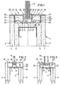
- Fig. 1 shows a usually in the interior of buildings, in particular Office buildings, inserted mounting wall 1, which is not shown Stand or frame construction and outer veneers 2, 3, in the present case - as usually - from two plasterboard panels 4, 5, 6, 7 are formed. Between the inner plates 5, 6 is adjacent to its common end face 8, a U-rail 9 is mounted, on the present embodiment, a plasterboard strip 10 is attached, which together with the plates 5, 6 a flat End face 8 forms.
- the rail 9 and the bar 10 can be glued or be screwed.
- the carrier strip 11 has a very thin flat Base plate 14, in the side areas from its top to top projecting continuous, so strip-shaped locking projections 15, 16 are formed, each at their also in the longitudinal direction continuous sides have undercuts 17, 18.
- a glass pane 19 is used, in the 1 is a single pane of glass 19 in FIG. She will be on only indicated blocks 20 placed on the base plate 14 of the carrier strip 11 between the locking projections 15, 16 are placed. Subsequently, two glass retaining strips 21, 22 on the locking projections 15, 16 locked. These retaining strips 21, 22 have substantially in cross-section the shape of a slotted box profile. They point outer plane, parallel to the glass pane 19 extending outer walls 23, which are provided with an inwardly projecting web 24 which in the each outer undercut 17 of the locking projections 15 or 16 can intervene.
- the glazing frame 12 arranged largely concealed, that is the outer plasterboard panels 4, 7 are so far beyond the front side 8 addition that they the respective outer wall 23 of the retaining strips 21, 22 cover.
- the visible side 25 of the retaining strips 21, 22 is extended so far outward that they each face the front the adjacent outer plate 4 and 7 covers.
- the insertion of the retaining strips 21, 22 takes place in such a way that a first Retaining strip 21 or 22 latched onto the locking projections 15 and 16 respectively is, wherein first the locking bar 27 in the inner undercut 18 used and then under elastic expansion of the retaining strip 21 and 22 of the web 24 is engaged in the outer undercut 17 becomes.
- the web 24 via one of the outer undercut 17 upstream inclined surface 17 a out, whereby the expansion of the Holding bar 21 and 22 is effected.
- the Sealing strips 28, 29 inserted.
- the sealing lips 30 of the Sealing strips 28, 29 deformed at the respective top of the glass sheet 19, so that the sealing strips 28, 29 transversely to the main plane of the glass 19 directed forces on the respective inner walls 26 of the retaining strips 21, 22 exercise.
- the locking webs 27 are thus firmly in the inside Undercuts 18 of the locking projections 15, 16 pressed. Disassembly is readily possible, with only those in purchase taken danger that the sealing strips 28, 29 are renewed have to.
- the sealing strips 28, 29 are made in the usual way of rubber or a suitable soft elastic plastic; they are endlessly extruded.
- the Carrier strip 11 and the retaining strips 21, 22 are usually made of aluminum and are also endlessly extruded. All parts will be on the Construction site only cut lengthwise. For fire safety reasons can it would be expedient to provide gypsum plasterboard strips 33 in the retaining strips 21, 22, which serve as a coolant in fires. This feature comes in the rest of the plasterboard strip 10 too.
- FIG. 2 differs from that of FIG. 1 only in that the strip 10 is omitted and that in the drawing right arranged retaining strip 22 'not through the outer plasterboard plate 7 'is concealed, but that the corresponding outer wall 23 is open. Accordingly, the outer wall 23 'is in alignment with the outside of the Plate 7 'brought.
- the web 24 is in this case via a bottom 35 of the bar 22 'connected to the outer wall 23'.
- the support bar 11 is directly by means a screw 13 'connected to the U-rail 9.
- the retaining strip 22 ' thus has a larger volume; the blind 3 'covers the associated one Retaining strip 22 'not off; the glazing frame 12 remains visible.
- FIG. 3 differs essentially only by it from the embodiment of Fig. 2 that the glass sheet as IsolierGlasscale 19 '' is formed.
- the retaining strips 21 '' and 22 '' are something formed narrow, that is, the inner walls 26 '' are closer to the respective Outside wall 23 and 23 'zoomed in, so that the locking webs 27 '' become relatively narrow.
- the support bar 11 is identical with those of Fig. 1 and 2. Externally seen differ Glazing frame 12 'of Fig. 2 and 12' 'of Fig. 3 hardly.
Landscapes
- Engineering & Computer Science (AREA)
- Architecture (AREA)
- Civil Engineering (AREA)
- Structural Engineering (AREA)
- Physics & Mathematics (AREA)
- Electromagnetism (AREA)
- Securing Of Glass Panes Or The Like (AREA)
Description
- Fig. 1
- einen an einer Stirnseite einer Montagewand angeordneten Verglasungsrahmen nach der Erfindung in montiertem Zustand in einer Querschnittsdarstellung,
- Fig. 2
- eine gegenüber Fig. 1 leicht abgewandelte Ausführungsform der Erfindung und
- Fig. 3
- eine weitere nochmals leicht abgewandelte Ausführungsform der Erfindung.
Claims (9)
- Verglasungsrahmen (12, 12', 12'') für Montagewände (1) mit zwei den Randbereich einer Glasscheibe (19, 19'') zwischen sich aufnehmenden Glas-Halteleisten (21, 22, 22', 21", 22"), wobei eine an einer Stirnseite (8) der Montage-Wand (1) anzubringende Trägerleiste (11) vorgesehen ist, die mindestens an einer Seite bezogen auf die Glasscheibe (19, 19") mit einem Verriegelungsvorsprung (15, 16) versehen ist, und wobei die mindestens eine nach Art eines geschlitzten Kastenprofils ausgebildete Glas-Halteleiste (21, 22, 22', 21", 22") mit dem mindestens einen Verriegelungsvorsprung (15, 16) elastisch verriegelbar ist, dadurch gekennzeichnet, dassein jeweiliger Verriegelungssteg (27, 27"), der in eine Hinterschneidung (18) des jeweiligen Verriegelungsvorsprunges (15, 16) eingreift, an einer zugewandt zur Glasscheibe (19, 19") anzuordnenden Innenwand (26) der Glas-Halteleiste (21, 22, 22', 21'', 22") ausgebildet ist, die elastisch auslenkbar ist, wobeian der Innenwand (26) der Glas-Halteleiste (21, 22, 22', 21'', 22") eine gegen die Glasscheibe (19, 19") anzulegende Dichtleiste (28, 29) angeordnet ist, die gegen Verschiebungen von der Trägerleiste (11) weg gesichert ist.
- Verglasungsrahmen (12, 12', 12") nach Anspruch 1, dadurch gekennzeichnet, dass die mindestens eine Glas-Halteleiste (21, 22, 22', 21'', 22") in ihrem geschlitzten Bereich einen Steg (24) und einen auf diesen zugerichteten Verriegelungssteg (27, 27") aufweist, die in Hinterschneidungen (17, 18) des jeweiligen Verriegelungsvorsprunges (15, 16) einrastbar sind.
- Verglasungsrahmen (12, 12', 12") nach Anspruch 1 oder 2, dadurch gekennzeichnet, dass an der Innenwand (26) ein sich in Längsrichtung der Glas-Halteleiste (21, 22, 22', 21'', 22'') erstreckender Haltesteg (31) ausgebildet ist, der in eine angepasste Ausnehmung (32) der Dichtleiste (28, 29) eingreift.
- Verglasungsrahmen (12, 12', 12") nach einem der Ansprüche 1 bis 3, dadurch gekennzeichnet, dass die Trägerleiste (11) mit zwei parallel zueinander verlaufenden, beiderseits der Glasscheibe (19, 19'') anzuordnenden Verriegelungsvorsprüngen (15, 16) versehen ist, und
dass zwei Glas-Halteleisten (21, 22, 22', 21'', 22'') zur elastischen Verriegelung mit den Verriegelungsvorsprüngen (15, 16) vorgesehen sind. - Verglasungsrahmen (12, 12', 12") nach einem der Ansprüche 1 bis 4, dadurch gekennzeichnet, dass die Trägerleiste (11) aus einer dünnen Grundplatte (14) und dem mindestens einen Verriegelungsvorsprung (15, 16) gebildet ist.
- Verglasungsrahmen (12, 12', 12'') nach einem der Ansprüche 1 bis 5, dadurch gekennzeichnet, dass die Trägerleiste (11) aus einem endlos stranggepressten Profil besteht.
- Verglasungsrahmen (12, 12', 12") nach einem der Ansprüche 1 bis 6, dadurch gekennzeichnet, dass die mindestens eine Glas-Halteleiste (21, 22, 22', 21'', 22'') durch ein endlos stranggepresstes Profil gebildet ist.
- Verglasungsrahmen (12) nach einem der Ansprüche 1 bis 7,
dadurch gekennzeichnet, dass in der mindestens einen Glas-Halteleiste (21, 22) ein Streifen (33) aus Gips oder Gipskarton angeordnet ist. - Verglasungsrahmen (12) nach einem der Ansprüche 1 bis 8, dadurch gekennzeichnet, dass eine Sichtseite (25) der Glas-Halteleisten (21, 22) soweit nach außen verlängert ist, dass sie jeweils Stirnseiten benachbarter äußerer Platten (4, 7) abdeckt.
Applications Claiming Priority (2)
| Application Number | Priority Date | Filing Date | Title |
|---|---|---|---|
| DE29910188U DE29910188U1 (de) | 1999-06-11 | 1999-06-11 | Verglasungsrahmen für Montagewände |
| DE29910188U | 1999-06-11 |
Publications (3)
| Publication Number | Publication Date |
|---|---|
| EP1059413A2 EP1059413A2 (de) | 2000-12-13 |
| EP1059413A3 EP1059413A3 (de) | 2002-01-23 |
| EP1059413B1 true EP1059413B1 (de) | 2005-11-30 |
Family
ID=8074654
Family Applications (1)
| Application Number | Title | Priority Date | Filing Date |
|---|---|---|---|
| EP00111744A Expired - Lifetime EP1059413B1 (de) | 1999-06-11 | 2000-06-02 | Verglasungsrahmen für Montagewände |
Country Status (3)
| Country | Link |
|---|---|
| EP (1) | EP1059413B1 (de) |
| AT (1) | ATE311516T1 (de) |
| DE (2) | DE29910188U1 (de) |
Families Citing this family (2)
| Publication number | Priority date | Publication date | Assignee | Title |
|---|---|---|---|---|
| DE202013100499U1 (de) * | 2013-02-04 | 2014-05-06 | Krause woodworking Kaliningrad AG | Haltevorrichtung für eine Glasscheibe in einem Türausschnitt |
| DE102013114417A1 (de) * | 2013-11-08 | 2015-05-28 | Schörghuber Spezialtüren KG | Deckenbefestigungsvorrichtung für ein Raumtrennelement sowie damit versehene Raumtrennung |
Family Cites Families (1)
| Publication number | Priority date | Publication date | Assignee | Title |
|---|---|---|---|---|
| DE29620668U1 (de) * | 1996-11-28 | 1997-02-06 | M T Z Metalltechnik GmbH, 90513 Zirndorf | Profilelement zur Festlegung einer Festverglasung |
-
1999
- 1999-06-11 DE DE29910188U patent/DE29910188U1/de not_active Expired - Lifetime
-
2000
- 2000-06-02 AT AT00111744T patent/ATE311516T1/de not_active IP Right Cessation
- 2000-06-02 DE DE50011728T patent/DE50011728D1/de not_active Expired - Lifetime
- 2000-06-02 EP EP00111744A patent/EP1059413B1/de not_active Expired - Lifetime
Also Published As
| Publication number | Publication date |
|---|---|
| EP1059413A3 (de) | 2002-01-23 |
| DE50011728D1 (de) | 2006-01-05 |
| ATE311516T1 (de) | 2005-12-15 |
| DE29910188U1 (de) | 1999-09-16 |
| EP1059413A2 (de) | 2000-12-13 |
Similar Documents
| Publication | Publication Date | Title |
|---|---|---|
| EP2666948B1 (de) | Rahmenanordnung für ein Sektionaltorpaneel | |
| DE3912136C2 (de) | ||
| EP1059413B1 (de) | Verglasungsrahmen für Montagewände | |
| EP1710363B1 (de) | Wandbausystem mit Glasplatten | |
| DE19707624C2 (de) | Dämmprofil für Befestigungsprofile für Fassadenplatten | |
| DE2609388A1 (de) | Stabilisierungs- und -ausrichtelement fuer gehrungsstoesse zwischen zwei bauprofilen | |
| DE9313426U1 (de) | Lüftungsvorrichtung für Räume | |
| EP1018316B1 (de) | Rost zur Bildung von Laufmatten, Fussabstreifern oder dergleichen | |
| EP0876788B1 (de) | Mit einem Wandhalter versehenes, im Querschnitt U-förmiges Halteprofil für eine Trennwand | |
| DE10157793C1 (de) | Profilanordnung zum Befestigen von Plattenelementen | |
| DE3636637A1 (de) | Rahmen mit plattenelementen, wie glastafeln, paneelen, oder dergleichen | |
| EP1763617B1 (de) | Vorrichtung zum abtrennen von raumbereichen eines raumes | |
| DE19546346C5 (de) | Anordnung zum Befestigen einer Glasfalzleiste auf einem Holzprofil für Fenster-, Tür-oder Fassadenelementrahmen | |
| DE9305394U1 (de) | Rahmenkonstruktion, insbesondere für Fassadenverkleidungen | |
| DE29617862U1 (de) | Wand- und/oder Türelement sowie Rahmenteil und Deckplatte zu dessen Herstellung | |
| DE102005001986A1 (de) | Modulare Fassade für Gebäude, Glasauflagedichtung und Schraube | |
| DE19803984C2 (de) | Fassadenkonstruktion für polygonzugartigen Grundriß | |
| EP1072731B1 (de) | Verglasungsrahmen für Montagewände | |
| DE4422153C1 (de) | Profilsatz zur Rundumverleistung von Fenster- oder Türelementen am Baukörper | |
| DE29812552U1 (de) | Zargenkonstruktion | |
| DE102021115733B4 (de) | Raffstorekasten und Verbindungsbeschlag zur Befestigung des Raffstores | |
| DE10145052B4 (de) | Satz von Innenfutterprofilleisten | |
| AT391163B (de) | Tuere | |
| EP0409029A1 (de) | Profil zur Halterung von Deckenplatten | |
| DE9304016U1 (de) | Schraubverbindung für Rahmenprofil-Kombinationen, insbesondere für Aluminium-Fassaden |
Legal Events
| Date | Code | Title | Description |
|---|---|---|---|
| PUAI | Public reference made under article 153(3) epc to a published international application that has entered the european phase |
Free format text: ORIGINAL CODE: 0009012 |
|
| AK | Designated contracting states |
Kind code of ref document: A2 Designated state(s): AT BE CH CY DE DK ES FI FR GB GR IE IT LI LU MC NL PT SE Kind code of ref document: A2 Designated state(s): AT BE DE IT NL |
|
| AX | Request for extension of the european patent |
Free format text: AL;LT;LV;MK;RO;SI |
|
| PUAL | Search report despatched |
Free format text: ORIGINAL CODE: 0009013 |
|
| AK | Designated contracting states |
Kind code of ref document: A3 Designated state(s): AT BE CH CY DE DK ES FI FR GB GR IE IT LI LU MC NL PT SE |
|
| AX | Request for extension of the european patent |
Free format text: AL;LT;LV;MK;RO;SI |
|
| 17P | Request for examination filed |
Effective date: 20020615 |
|
| AKX | Designation fees paid |
Free format text: AT BE DE IT NL |
|
| 17Q | First examination report despatched |
Effective date: 20050214 |
|
| GRAP | Despatch of communication of intention to grant a patent |
Free format text: ORIGINAL CODE: EPIDOSNIGR1 |
|
| RAP1 | Party data changed (applicant data changed or rights of an application transferred) |
Owner name: R&M AUSBAU GMBH |
|
| GRAS | Grant fee paid |
Free format text: ORIGINAL CODE: EPIDOSNIGR3 |
|
| GRAA | (expected) grant |
Free format text: ORIGINAL CODE: 0009210 |
|
| AK | Designated contracting states |
Kind code of ref document: B1 Designated state(s): AT BE DE IT NL |
|
| PG25 | Lapsed in a contracting state [announced via postgrant information from national office to epo] |
Ref country code: NL Free format text: LAPSE BECAUSE OF FAILURE TO SUBMIT A TRANSLATION OF THE DESCRIPTION OR TO PAY THE FEE WITHIN THE PRESCRIBED TIME-LIMIT Effective date: 20051130 |
|
| REF | Corresponds to: |
Ref document number: 50011728 Country of ref document: DE Date of ref document: 20060105 Kind code of ref document: P |
|
| NLV1 | Nl: lapsed or annulled due to failure to fulfill the requirements of art. 29p and 29m of the patents act | ||
| PG25 | Lapsed in a contracting state [announced via postgrant information from national office to epo] |
Ref country code: BE Free format text: LAPSE BECAUSE OF NON-PAYMENT OF DUE FEES Effective date: 20060630 |
|
| PGFP | Annual fee paid to national office [announced via postgrant information from national office to epo] |
Ref country code: IT Payment date: 20060630 Year of fee payment: 7 |
|
| PLBE | No opposition filed within time limit |
Free format text: ORIGINAL CODE: 0009261 |
|
| STAA | Information on the status of an ep patent application or granted ep patent |
Free format text: STATUS: NO OPPOSITION FILED WITHIN TIME LIMIT |
|
| 26N | No opposition filed |
Effective date: 20060831 |
|
| BERE | Be: lapsed |
Owner name: R&M AUSBAU G.M.B.H. Effective date: 20060630 |
|
| PGFP | Annual fee paid to national office [announced via postgrant information from national office to epo] |
Ref country code: AT Payment date: 20080530 Year of fee payment: 9 |
|
| PG25 | Lapsed in a contracting state [announced via postgrant information from national office to epo] |
Ref country code: IT Free format text: LAPSE BECAUSE OF NON-PAYMENT OF DUE FEES Effective date: 20070602 |
|
| PG25 | Lapsed in a contracting state [announced via postgrant information from national office to epo] |
Ref country code: AT Free format text: LAPSE BECAUSE OF NON-PAYMENT OF DUE FEES Effective date: 20090602 |
|
| PGFP | Annual fee paid to national office [announced via postgrant information from national office to epo] |
Ref country code: DE Payment date: 20100812 Year of fee payment: 11 |
|
| REG | Reference to a national code |
Ref country code: DE Ref legal event code: R119 Ref document number: 50011728 Country of ref document: DE Effective date: 20120103 |
|
| PG25 | Lapsed in a contracting state [announced via postgrant information from national office to epo] |
Ref country code: DE Free format text: LAPSE BECAUSE OF NON-PAYMENT OF DUE FEES Effective date: 20120103 |