EP1059277A1 - Verfahren zur Umsetzung von aromatischen Kohlenwasserstoffen - Google Patents
Verfahren zur Umsetzung von aromatischen Kohlenwasserstoffen Download PDFInfo
- Publication number
- EP1059277A1 EP1059277A1 EP00202004A EP00202004A EP1059277A1 EP 1059277 A1 EP1059277 A1 EP 1059277A1 EP 00202004 A EP00202004 A EP 00202004A EP 00202004 A EP00202004 A EP 00202004A EP 1059277 A1 EP1059277 A1 EP 1059277A1
- Authority
- EP
- European Patent Office
- Prior art keywords
- benzene
- alkylation
- transalkylation
- zone
- reaction zone
- Prior art date
- Legal status (The legal status is an assumption and is not a legal conclusion. Google has not performed a legal analysis and makes no representation as to the accuracy of the status listed.)
- Granted
Links
Images


Classifications
-
- C—CHEMISTRY; METALLURGY
- C07—ORGANIC CHEMISTRY
- C07C—ACYCLIC OR CARBOCYCLIC COMPOUNDS
- C07C6/00—Preparation of hydrocarbons from hydrocarbons containing a different number of carbon atoms by redistribution reactions
- C07C6/08—Preparation of hydrocarbons from hydrocarbons containing a different number of carbon atoms by redistribution reactions by conversion at a saturated carbon-to-carbon bond
- C07C6/12—Preparation of hydrocarbons from hydrocarbons containing a different number of carbon atoms by redistribution reactions by conversion at a saturated carbon-to-carbon bond of exclusively hydrocarbons containing a six-membered aromatic ring
- C07C6/126—Preparation of hydrocarbons from hydrocarbons containing a different number of carbon atoms by redistribution reactions by conversion at a saturated carbon-to-carbon bond of exclusively hydrocarbons containing a six-membered aromatic ring of more than one hydrocarbon
-
- C—CHEMISTRY; METALLURGY
- C07—ORGANIC CHEMISTRY
- C07C—ACYCLIC OR CARBOCYCLIC COMPOUNDS
- C07C6/00—Preparation of hydrocarbons from hydrocarbons containing a different number of carbon atoms by redistribution reactions
- C07C6/08—Preparation of hydrocarbons from hydrocarbons containing a different number of carbon atoms by redistribution reactions by conversion at a saturated carbon-to-carbon bond
- C07C6/12—Preparation of hydrocarbons from hydrocarbons containing a different number of carbon atoms by redistribution reactions by conversion at a saturated carbon-to-carbon bond of exclusively hydrocarbons containing a six-membered aromatic ring
-
- C—CHEMISTRY; METALLURGY
- C07—ORGANIC CHEMISTRY
- C07C—ACYCLIC OR CARBOCYCLIC COMPOUNDS
- C07C15/00—Cyclic hydrocarbons containing only six-membered aromatic rings as cyclic parts
- C07C15/02—Monocyclic hydrocarbons
- C07C15/067—C8H10 hydrocarbons
- C07C15/073—Ethylbenzene
-
- C—CHEMISTRY; METALLURGY
- C07—ORGANIC CHEMISTRY
- C07C—ACYCLIC OR CARBOCYCLIC COMPOUNDS
- C07C2529/00—Catalysts comprising molecular sieves
- C07C2529/04—Catalysts comprising molecular sieves having base-exchange properties, e.g. crystalline zeolites, pillared clays
- C07C2529/06—Crystalline aluminosilicate zeolites; Isomorphous compounds thereof
- C07C2529/40—Crystalline aluminosilicate zeolites; Isomorphous compounds thereof of the pentasil type, e.g. types ZSM-5, ZSM-8 or ZSM-11
Definitions
- This invention involves the transalkylation of aromatic compounds over a high porosity zeolite-Y molecular sieve and such transalkylation in combination with alkylation of an aromatic substrate such as benzene over a silicalite aromatic alkylation catalyst having an average pore size less than that of the zeolite-Y catalyst.
- Aromatic conversion processes which are carried out over molecular sieve catalyst are well known in the chemical processing industry. Such aromatic conversion reactions include the alkylation of aromatic substrates such as benzene to produce alkyl aromatics such as ethylbenzene, ethyltoluene, cumene or higher aromatics and the transalkylation of polyalkyl benzenes to monoalkyl benzenes.
- Transalkylation reactors are normally employed in an interated process which involves an initial alkylation of the aromatic substrate followed by an intermediate recovery operation and then transalkylation.
- an alkylation reactor which produces a mixture of mono- and poly- alkyl benzenes is coupled through several separation stages to the downstream transalkylation reactor. Transalkylation may, in turn, be followed by separation and or recycle procedures.
- Such alkylation and transalkylation conversion processes can be carried out in the liquid phase, in the vapor phase, or under conditions in which both liquid and vapor phases are present.
- the alkylation product within the reactor includes not only ethylbenzene but also polyethylbenzene, principally diethylbenzene with reduced amounts of triethylbenzene, as well as other alkylated aromatics such as cumene and butylbenzene.
- the molecular sieves employed in the separate alkylation and transalkylation reactors can be the same or different. As described below, it is often the practice to employ a relatively small to intermediate pore size molecular sieve such as ZSM-5, ZSM-11, or silicalite in the alkylation reactor and follow this with a molecular sieve having a somewhat larger pore size, such as zeolite-Y, zeolite- ⁇ , , or mordenite. However, as indicated by the following discussion, this procedure is by no means universally followed.
- vapor phase alkylation is found in U.S. Patent No. 4,107,224 to Dwyer.
- vapor phase ethylation of benzene over a zeolite catalyst is accomplished in a down flow reactor having four series connected catalyst beds.
- the output from the reactor is passed to a separation system in which ethylbenzene product is recovered, with the recycle of polyethylbenzenes to the alkylation reactor where they undergo transalkylation reactions with benzene.
- the Dwyer catalysts are characterized in terms of those having a constraint index within the approximate range of 1-12 and include, with the constraint index in parenthesis, ZSM-5 (8.3), ZSM-11 (8.7), ZSM-12 (2), ZSM-35 (4.5), ZSM-38 (2), and similar materials.
- the molecular sieve silicalite referred to above is a well-known alkylation catalyst.
- U.S. Patent No. 4,520,220 to Watson et al discloses the use of silicalite catalysts having an average crystal size of less than 8 microns and a silica/alumina ratio of at least about 200 in the ethylation of an aromatic substrate such as benzene or toluene to produce ethylbenzene or ethyltoluene, respectively.
- the alkylation procedure can be carried out in a multi-bed alkylation reactor at temperatures ranging from about 350°-500°C. and, more desirably, about 400°-475°C, with or without a steam co-feed.
- the reactor conditions in Watson et al are such as to provide generally for vapor phase alkylation conditions.
- silicalite is employed as a catalyst in the alkylation of a monoalkylated substrate, toluene or ethylbenzene, in order to produce the corresponding dialkylbenzene, such as ethyl toluene or diethylbenzene.
- Butler et al is the ethylation of toluene to produce ethyltoluene under vapor phase conditions at temperatures ranging from 350°-500°C.
- the presence of ortho ethyltoluene in the reaction product is substantially less than the thermodynamic equilibrium amount at the vapor phase reaction conditions employed.
- alkylation is carried out at temperatures generally in the range of 370°C. to about 470°C. and pressures ranging from atmospheric up to about 25 atmospheres over a catalyst such as silicalite or ZSM-5.
- the catalysts are described as being moisture sensitive and care is taken to prevent the presence of moisture in the reaction zone.
- the alkylation/transalkylation reactor comprises four series connected catalyst beds.
- Benzene and ethylene are introduced into the top of the reactor to the first catalyst bed coupled by recycle of a polyethylbenzene fraction to the top of the first catalyst bed as well as the interstage injection of polyethylbenzene and benzene at different points in the reactor.
- U.S. Patent No. 4,185,040 to Ward et al discloses an alkylation process employing a molecular sieve catalyst of low sodium content which is said to be especially useful in the production of ethylbenzene from benzene and ethylene and cumene from benzene and propylene.
- the Na 2 O content of the zeolite should be less than 0.5 wt.%.
- suitable zeolites include molecular sieves of the X, Y, L, B, ZSM-5, and omega crystal types, with steam stabilized hydrogen Y zeolite being preferred. Specifically disclosed is a steam stabilized ammonium Y zeolite containing about 0.2% Na 2 O.
- Various catalyst shapes are disclosed in the Ward et al patent. While cylindrical extrudates may be employed, a particularly preferred catalyst shape is a so-called "trilobal" shape which is configured as something in the nature of a three leaf clover. The surface area volume ratio of the extrudate should be within the range of 85-160 in. -1 .
- the alkylation process may be carried out with either upward or downward flow, the latter being preferred, and preferably under temperature and pressure conditions so that at least some liquid phase is present, at least until substantially all of the olefin alkylating agent is consumed. Ward et al states that rapid catalyst deactivation occurs under most alkylating conditions when no liquid phase is present.
- U.S. Patent No. 4,169,111 to Wight discloses an alkylation/ transalkylation process for the manufacture of ethylbenzene employing crystalline aluminosilicates in the alkylation and transalkylation reactors.
- the catalysts in the alkylation and transalkylation reactors may be the same or different and include low sodium zeolites having silica/alumina mole ratios between 2 and 80, preferably between 4-12.
- Exemplary zeolites include molecular sieves of the X, Y, L, B, ZSM-5 and omega crystal types with steam stabilized Y zeolite containing about 0.2% Na 2 O being preferred.
- the alkylation reactor is operated in a downflow mode and under temperature and pressure conditions in which some liquid phase is present.
- the output from the alkylating reactor is cooled in a heat exchanger and supplied to a benzene separation column from which benzene is recovered overhead and recycled to the alkylation reactor.
- the initial higher boiling bottoms fraction from the benzene column comprising ethylbenzene and polyethylbenzene is supplied to an initial ethylbenzene column from which the ethylbenzene is recovered as the process product.
- the bottoms product from the ethylbenzene column is supplied to a third column which is operated to provide a substantially pure diethylbenzene overheads fraction which contains from 10 to 90%, preferably 20 to 60% of diethylbenzene.
- the diethylbenzene overheads fraction is recycled to the alkylation reactor while a side cut containing the remaining diethylbenzene and triethylbenzene and higher molecular weight compounds is supplied to the reactor along with benzene.
- the effluent from the reactor is recycled through the heat exchanger to the benzene column.
- U.S. Patent No. 4,774,377 to Barger et al discloses an alkylation transalkylation process which, involves the use of separate alkylation and transalkylation reaction zones, with recycle of the transalkylated product to an intermediate separation zone.
- the transalkylation catalyst is an aluminosilicate molecular sieve including X-type, Y-type, ultrastable-Y, L-type, omega type and mordenite type zeolites with the latter being preferred.
- the catalyst employed in the alkylation reaction zone is a solid phosphoric acid containing material.
- Aluminosilicate alkylation catalysts may also be employed and water varying from 0.01 to 6 volume percent is supplied to the alkylation reaction zone.
- the output from the alkylation reaction zone is supplied to first and second separation zones. Water is recovered in the first separation zone.
- intermediate aromatic products and trialkylaromatic and heavier products are separated to provide an input to the transalkylation reaction zone having only dialkyl aromatic components, or diethylbenzene in the case of an ethylbenzene manufacturing procedure or diisopropylbenzene in the case of cumene production.
- a benzene substrate is also supplied to the transalkylation zone for the transalkylation reaction and the output from the transalkylation zone is recycled to the first separation zone.
- the alkylation and transalkylation zones may be operated in downflow, upflow, or horizontal flow configurations.
- EPA publication 467,007 to Butler discloses other processes having separate alkylation and transalkylation zones employing various molecular sieve catalysts and with the output from the transalkylation reactor being recycled to an intermediate separation zone.
- a benzene separation zone from which an ethylbenzene/polyethylbenzene fraction is recovered from the bottom with recycling of the overhead benzene fraction to the alkylation reactor is preceded by a prefractionation zone.
- the prefractionation zone produces an overhead benzene fraction which is recycled along with the overheads from the benzene column and a bottom fraction which comprises benzene, ethylbenzene and polyethylbenzene.
- Two subsequent separation zones are interposed between the benzene separation zone and the transalkylation reactor to provide for recovery of ethylbenzene as the process product and a heavier residue fraction.
- the polyethylbenzene fraction from the last separation zone is applied to the transalkylation reactor and the output there is applied directly to the second benzene separation column or indirectly through a separator and then to the second benzene separation column.
- Butler discloses that the alkylation reactor may be operated in the liquid phase with a catalyst such as zeolite- ⁇ , zeolite-Y or zeolite- ⁇ or in the vapor phase employing a catalyst such as silicalite or ZSM-5.
- the transalkylation catalyst may take the form of a zeolite-Y or zeolite- ⁇ .
- a process for the transalkylation of polyalkylated aromatic compounds over a high porosity zeolite-Y molecular sieve is characterized as having a surface area of no more than 500 m 2 /g, as contrasted with a surface area of standard zeolite-Y catalysts ranging from more than 600 m 2 /g to as much as 700-800 m 2 /g.
- the surface area of a molecular sieve catalyst provides an inverse measurement of its porosity; that is, surface area is inversely proportionate to its porosity.
- a feedstock comprising a polyalkylated aromatic component, including polyalkylbenzenes in which the predominant alkyl substituents contain from 2 to 4 carbon atoms, is supplied to a transalkylation reaction zone containing the high porosity zeolite-Y catalyst.
- Benzene is also supplied to the transalkylation zone, and the reaction zone is operated under temperature and pressure conditions to maintain the polyalkylated aromatic component in the liquid phase and which are effective to cause disproportionation of the polyalkylated aromatic component to arrive a disproportionation product having a reduced polyalkylbenzene content in an enhanced monoalkylbenzene content.
- the high porosity zeolite-Y molecular sieve used in the reaction zone has a surface area of about 400 m 2 /g or less and, more specifically, a surface area within the range of about 350-400 m 2 /g.
- the polyalkylated benzene comprises alkyl substituents containing 2 or 3 carbon atoms, and more specifically, the polyalkylated aromatic component comprises polyethylbenzene.
- an alkylation reaction zone which contains a molecular sieve aromatic alkylation catalyst having an average pore size which is less than the average pore size of the average pore size of the high porosity zeolite-Y.
- a feedstock comprising benzene in a C 2 -C 4 alkylating agent is supplied to the alkylation reaction zone which is operated under conditions to produce alkylation of the benzene by the alkylating agent in the presence of the molecular sieve alkylation catalyst.
- the resultant alkylated product comprises a mixture of monoalkylated and polyalkylated aromatic components.
- the alkylation product from the alkylation reaction zone is supplied to an intermediate recovery zone for the separation and recovery of a monoalkylbenzene, e.g. ethylbenzene, from the alkylation product, together with the recovery of a polyalkylated aromatic component employing a dialkylbenzene, e.g. diethylbenzene.
- a monoalkylbenzene e.g. ethylbenzene
- a polyalkylated aromatic component employing a dialkylbenzene, e.g. diethylbenzene.
- the polyalkylated aromatic component is employed in at least a portion of the feedstream supplied to the transalkylation reactor.
- a preferred embodiment of the present invention involves vapor phase alkylation of an aromatic substrate comprising benzene in a multistage reaction zone followed by liquid phase transalkylation in which the alkylation and transalkylation reactors are integrated with intermediate separation zones in a manner to effectively provide feed streams to the reactors with recycle of the output from the transalkylation reactor to a benzene recovery zone downstream of the alkylation reactor.
- the transalkylation product is applied to an initial stage of a benzene recovery zone. Subsequent separation steps are carried out in a manner to apply a split feed to the transalkylation reactor.
- the alkylation reactor is a multistage reaction zone containing at least three series connected catalyst beds which contain a pentasil molecular sieve aromatic alkylation catalyst, preferably a silicalite alkylation catalyst.
- the silicalite alkylation catalyst preferably is silicalite characterized as having a high monoclinicity and a small sodium content.
- the catalyst used in the transalkylation reactor is a high porosity zeolite-Y having the characteristics described above.
- the alkylation reactor is normally operated at substantially higher temperature conditions than the transalkylation reactor, and if desired, the recycled output from the transalkylation reactor is passed in a heat exchange relationship with the alkylation reactor product feed to the initial benzene separation zone.
- a further aspect of the invention involves a multistage alkylation reactor with the output coupled to a four-stage separation system which in turn supplies a polyethylbenzene feed to a transalkylation reactor.
- parallel alkylation and transalkylation reactors are employed so that simultaneous catalyst regeneration can occur during operation of the alkylation and transalkylation reactions.
- the alkylation reactor comprises at least four catalyst beds. More beds can be provided, and it will sometimes be advantageous to provide at least five catalyst beds in the alkylation reactor.
- the reactor is operated so as to provide vapor phase alkylation (both the aromatic substrate and the alkylating agent are in the vapor phase) at temperatures ranging from about 630°F.- 800°F.
- the pressure may be within the range of about 250 to 450 psia with the pressure decreasing from one bed to the next as the temperature increases.
- the benzene and ethylene supplied to the top of the reactor may enter the reactor at a temperature of about 740°F and a pressure of about 430 psia.
- the alkylation reaction is exothermic so that the temperature progressively increases from the first to the last catalyst bed by a way or example.
- the interstage temperatures may increase from 750°F for the first catalyst bed to 765°F after the second catalyst bed to 820°F after the third catalyst bed to a temperature of about 840°F after the last catalyst bed.
- benzene and ethylene (or other alkylating agent) is introduced as a mixture to the first catalyst bed at the top of the reaction zone and also in between the several successive stages of catalyst beds.
- ethylene is supplied along with benzene to the top of the catalyst bed top of the reactor.
- interstage injection or ethylene and benzene is provided for between the subsequent catalyst beds.
- the benzene to ethylene mole ratio is about 18 as injected into the top of the alkylation reactor and progressively decreases because of the interstage injection of ethylene and of course the alkylation of the benzene to ethyl benzene and polyethylbenzenes.
- the preferred silicalite alkylation catalyst employed in the integrated process of the present invention does not require the presence of water to stabilize the catalyst, so a water or steam co-feed, as is sometimes used in connection with silicalite, is not called for in this invention.
- Interstage injection of ethylene is normally employed.
- the interstage injection of the benzene or other aromatic substrate can also be provided for.
- the mole ratio of the aromatic substrate to the ethylene at the interstage injection points can vary from zero (no benzene injection) up to about five.
- the benzene in many cases will be employed in an amount less than the amount of ethylene on a mole basis.
- benzene can either not be injected between the catalyst beds or, if injected, can be employed in a relatively minor amount, i.e., a mole ratio of benzene to ethylene of less than one.
- the mole ratio of the aromatic substrate to the alkylating agent can be as high as five. This is coupled with a somewhat lower operating temperature than would normally be the case for vapor phase alkylation.
- the temperature of the benzene stream into the top of the alkylation reactor will be in the order of 720°F. or lower.
- the alkylation reaction is, of course, an exothermic reaction so that the temperature will be increased progressively throughout the alkylation column as noted previously.
- the zeolite-Y transalkylation catalyst employed in the present invention is topologically similar to standard zeolite-Y in terms of crystal structure faujasite and silica alumina ratio.
- the zeolite-Y should have a silica alumina atomic ratio within the range of 2-5 and such catalysts are normally characterized as being intermediate silica alumina ratio zeolites.
- Zeolite-Y in the hydrogen form exhibits a pore size of about 7 and a surface area which is usually in excess of about 600 m 2 /g and is usually in the range of about 700-800 m 2 / g.
- Zeolite-Y typically has a crystallite size of about one micron and a unit cell size of about 24.5 Angstroms.
- the high porosity zeolite-Y used in the present invention has a substantially lower surface area, indicative of a somewhat larger pore size, greater than 7 and ranging up to about 8 Angstroms ( ⁇ )and a bulk density which is about 10-20% less than the bulk density of normal zeolite-Y.
- the foregoing catalyst characteristics are for the zeolite-Y catalyst as it exists in the crystallite form.
- the zeolite-Y catalyst as in the case of other molecular sieve catalysts, will be mulled with a binder such as silica or alumina and extruded to catalyst particles.
- the catalyst may be used in the form of cylindrical extrudates, typically of 1/16 to 1/8 inch in diameter or in the nature of trilobal shapes as described in the aforementioned Patent No. 4,185,040 to Ward et al.
- the high porosity zeolite-Y has a larger pore size and also a larger crystal size.
- the preferred alkylation catalyst is a molecular sieve from the pentasil family of high silica molecular sieves or zeolites.
- pentasil molecular sieves are described, for example, in Kokotailo et al. "Pentasil Family of High Silica Crystalline Materials.” Chem. Soc. Special Publ. 33, 133-139 (1980).
- These molecular sieves pentasils can include high silica alumina ratio ZSM-5. such as described, for example, in Wu et al, "ZSM-5-Type Materials. Factors Affecting Crystal Symmetry.” The Journal of Physical Chemistry , Vol. 83, No. 21. 1979.
- silicalite molecular sieves as described, for example, in Gourgue et al. "Physico-chemical characterization or pentasil type materials, I. Precursors and calcined zeolites," Zeolites, 1985, Vol. 5, November, and Gourgue et al, "Physico-chemical characterization or pentasil type materials, II. Thermal analysis of the precursors, Zeolites, 1985, Vol 5, November.
- the silicalite or other pentasil molecular sieve alkylation catalyst has a somewhat smaller pore size than the high porosity zeolite-Y employed in the transalkylation reactor.
- the preferred silicalite catalyst has a somewhat smaller crystal size than is usually the case.
- the crystal size is about 0.5 ⁇ , or even somewhat smaller, as contrasted with a crystal sizes of perhaps 1-2 ⁇ for similar catalysts.
- a preferred silicalite for use with high porosity zeolite-Y in the present invention is extruded with an alumina binder in a "trilobe" shape having a nominal diameter of about 1/16" and a length of the extrudate of about 1/8-1/4".
- the "trilobe" cross sectional shape is something on the order of a three leaf clover. The purpose of this shape is to increase the surface area of the extruded catalyst beyond what one would expect with a normal cylindrical extrudate.
- the preferred silicalite catalyst is characterized as monoclinic silicalite. Monoclinic silicalite may be prepared as disclosed in U.S. Patent Nos.
- the catalysts will have near 100% monoclinicity) although silicalite catalysts that are 70-80% monoclinic and about 20-30% orthorhombic symmetry may be used in the preferred embodiment of the invention.
- the silicalite preferably is present in an amount of 75-80 wt.% with the alumina binder being present in an amount of 20-25 wt.%.
- the silica/alumina ratio of the preferred silicalite is about 200, or more normally, 225.
- the silicalite may have an alpha value of about 20-30.
- the "alpha value" is characterized in terms or the activity of a catalyst for tracking hexane as disclosed in U.S. Patent Nos. 4,284,529 to Shihabi and 4,559,314 to Shihabi.
- the catalyst contains small amounts of sodium and iron.
- the preferred silicalite catalyst has a crystal structure characterized by an aluminum rich outer shell and an aluminum deficient interior portion when compared with the outer shell.
- the silicalite catalyst is dry and has no appreciable or intended water content.
- the alumni binder is a high purity alumina such as "catapal alumina.”
- the silicalite catalyst preferably contains only a small amount of sodium, about 70-200 ppm sodium oxide, and contains only a small amount of iron oxide, about 300-600 ppm.
- the catalyst need not contain any additional "promoter” metals incorporated during the synthesis of the catalyst.
- the silicalite alkylation catalyst like the high porosity zeolite-Y, preferably is extruded with a binder, such as an alumina binder, in an amount of about 20 wt.%.
- a binder such as an alumina binder
- the preferred binder is one providing a relatively large pore size, not to be confined with the pore size of the zeolite itself, of about 1,000-1,800 angstroms.
- the average pore size as determined by the binder may range up to as high as about 4,000 angstroms.
- the silicalite alkylation catalysts will normally have a silica/alumina ratio of about 220 to 320 and is of predominantly monoclinic symmetry.
- a product stream comprising a mixture of ethylene and benzene in a mole ratio of benzene to ethylene about 5 to 20 supplied via line 1 to an alkylation zone 2.
- Alkylation zone 2 comprises one or more multi-stages reactor having a plurality of series-connected catalyst beds containing the preferred high silica/alumina ratio silicalite as described in greater detail below.
- the alkylation zone is operated at temperature and pressure conditions to maintain the alkylation reaction in the vapor phase, i.e. the aromatic substrate is in the vapor phase, and at a feed rate to provide a space velocity enhancing diethylbenzene production while retarding xylene production.
- the output from the alkylation reactor is supplied via line 3 to an intermediate recovery zone 4 which provides for the separation and recovery of ethylbenzene as a product.
- ethylbenzene is withdrawn from zone 4 via line 4a and applied for any suitable purposes such as in the production of vinylbenzene.
- Recovery zone 4 normally will be characterized by a plurality of series-connected distillation columns as described below and will result in a heavy polyalkylated product stream which is supplied via line 5 to a transalkylation zone 6.
- benzene will also be recovered from the intermediate recovery zone via a line 4b.
- the benzene may be applied as indicated by the broken lines both for recycle back to the alkylation reactor and also to the transalkylation zone as may be appropriate.
- the benzene and diethylbenzene undergo a disproportionation reaction resulting in a product of enhanced ethylbenzene content and diminished benzene and diethylbenzene content.
- at least part of the output from the transalkylation zone will be supplied via line 7 for recycle to the separation zone 4.
- a suitable system incorporating a multi-stage intermediate recovery zone for the separation and recycling of components involved in the integrated alkylation/transalkylation process.
- an input feed stream is supplied by fresh ethylene through line 11 and fresh benzene through line 12.
- Line 12 is provided with a preheater 14 to heat the benzene stream to the desired temperature for the alkylation reaction.
- the feedstream is applied through a two-way, three-position valve 16 and inlet line 17 to the top of an alkylation reaction zone 18 which comprises a plurality of series connected catalyst beds each of which contains a silicalite alkylation catalyst.
- the reactor is operated at an average temperature, preferably within the range of 700°F-800°F and at pressure conditions of about 200 to 350 psia, to maintain the benzene in the gaseous phase.
- a second reaction zone 20 is schematically shown to be in the "off-line" position for regeneration of the catalyst.
- both reaction zones 18 and 20 are operated in a parallel mode of operation in which they are both in service at the same time. That is, valve 16 is configured so that all of the flow from line 10 is directed to the top of reactor 18.
- the reactor 18 comprises four series connected catalyst beds designated as beds A, B, C and D.
- An ethylene feed stream is supplied via line 19 and proportionating valves 19a, 19b and 19c to provide for the appropriate interstage injection of ethylene.
- Benzene can also be introduced between the catalyst stages by means of secondary benzene supply lines 21a, 21b and 22b, respectively.
- the parallel reactor 20 will be configured with similar manifolding as shown in FIGURE 3 with respect to reactor 18.
- the effluent stream from the alkylation reactor 18 is supplied through a two position outlet valve 24 and outlet line 25 to a two-stage benzene recovery zone which comprises as the first stage a prefractionation column 27.
- Column 27 is operated to provide a light overhead fraction including benzene which is supplied via line 28 to line 15 where it is mixed with benzene from line 12 and then to the alkylation reactor input line 10.
- a heavier liquid fraction containing benzene, ethylbenzene and polyethylbenzene is supplied via line 30 to the second stage 32 of the benzene separation zone.
- Stages 27 and 32 may take the form at distillation columns of any suitable type, typically, columns having from about 20-60 trays.
- the overheads fraction from column 32 contains the remaining benzene which is recycled via line 34 to the alkylation reactor input.
- the heavier bottoms fraction from column 32 is supplied via line 36 to a secondary separation zone 38 for the recovery of monoalkylated aromatic component. e.g. ethylbenzene.
- the overheads fraction from column 38 comprises relatively pure ethylbenzene which is supplied to storage or to any suitable product destination by way of line 40.
- the ethylbenzene may be used as a feedstream to a styrene plant in which styrene is produced by the dehydrogenation of ethylbenzene.
- the bottoms fraction containing polyethylbenzenes, heavier aromatics and normally only a small amount of ethylbenzene is supplied through line 41 to a tertiary polyethylbenzene separation zone 42.
- the bottoms fraction of column 42 comprises a residue which can be withdrawn from the process via line 44 for further use in any suitable manner.
- the overhead fraction from column 42 comprises a polyalkylated aromatic component containing diethylbenzene and triethylbenzene (usually in relatively small quantities) and a minor amount of ethylbenzene is supplied to an on stream transalkylation reaction zone.
- parallel transalkylation reactors 45 and 46 are provided through inlet and outlet connections involving valves 47 and 48. While one transalkylation reactor is on-stream, the other can be undergoing regeneration operation in order to burn coke off the catalyst beds. Alternatively, both of reactors 45 and 46 can be placed on stream at the same time so that both are in service in a parallel mode of operation.
- the ethylbenzene content of the transalkylation feedstream can be kept small in order to drive the transalkylation reaction in the direction of ethylbenzene production.
- the polyethylbenzene fraction withdrawn overhead from column 42 through line 49 is mixed with benzene supplied via line 50 and then supplied to the on- line transalkylation reactor 45 via line 51.
- the benzene feed supplied via line 50 is of relatively low water content, about 0.05 wt.% or less.
- the water content is reduced to a level of about 0.02 wt.% or less and more preferably to no more than 0.01 wt.%.
- the transalkylation reactor is operated as described before in order to maintain the benzene and alkylated benzenes within the transalkylation reactor in the liquid phase.
- the alkylation reactor and transalkylation reactor may be operated to provide an average temperature within the transalkylation reactor of about 150°F-550°F. and an average pressure of about 600 psi.
- the catalyst employed in the transalkylation reactor is the high porosity zeolite-Y having the characteristics described previously.
- the weight ratio of benzene to polyethylbenzene should be at least 1:1 and preferably is within the range of 1:1 to 4:1.
- the output from the transalkylation reactor containing benzene, ethylbenzene and diminished amounts of polyethylbenzene is supplied via line 52 to the initial stage of the benzene recovery zone.
- This mode of operation is contrary to the normal mode of operation as disclosed in the aforementioned EPA 467,007 to Butler.
- the output from the tansalkylation reactor is supplied to the second stage of the benzene recovery zone, corresponding to column 32 in FIGURE 2. While this mode of operation can be followed in carrying out the present invention, it is preferred to operate, as shown in FIGURE 2, in which the transalkylation reactor output is supplied to the initial stage 27 of the benzene recovery zone. This offers the advantage of having a stream with approximately the same benzene and ethylbenzene composition as the stream from the alkylation reaction.
- the entire bottoms fraction from the ethylbenzene separation column 38 is applied to the tertiary separation column 42 with overhead fractions from this zone then applied to the transalkylation reactor.
- This mode of operation offers the advantage of relatively long cycle lengths of the catalyst in the transalkylation reactor between regeneration of the catalyst to increase the catalyst activity.
- Another embodiment of the invention achieves this advantage by supplying a portion of the output from the ethylbenzene separation column directly to the transalkylation reactor.
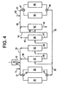
- vapor phase alkylation coupled with liquid phase transalkylation in accordance with the present invention, a significant quantity of the bottoms fraction from the ethylbenzene column can be sent directly to the transalkylation reactor, thus decreasing the amount of residue which is lost from the process. While applicants invention is not to be limited by theory, it is believed that direct application of a substantial portion of the output from the ethylbenzene separation zone to the tansalkylation reactor is made possible, at least in part, by the low water content in the process stream resulting from low water content introduced initially into the transalkylation reactor.
- FIGURE 4 This embodiment of the invention is shown in FIGURE 4 in which like elements and components as are shown in FIGURE 2 are illustrated by the same reference numerals as used in FIGURE 2.
- a portion of the bottoms fraction from the secondary separation zone 38 is supplied directly to the transalkylation reactor 45 via line 54.
- a second portion of the bottoms fraction from the ethylbenzene column is applied to the tertiary separation column 42 via line 55.
- the overhead fraction from column 42 is commingled with the bypass effluent in line 54 and the resulting mixture is fed to the transalkylation reactor via line 47.
- a substantial amount of the bottoms product from column 38 is sent directly to the transalkylation reactor, bypassing the polyethylbenzene column 42.
- the weight ratio of the first portion supplied via line 54 directly to the transalkylation reactor to the second portion supplied initially via line 55 to the polyethylbenzene would be within the range of about 1:2 to about 2:1.
- the relative amounts may vary somewhat more widely to be within the range of a weight ratio of the first portion to the second portion in a ratio of about 1:3 to 3:1.
- FIGURE 2 or FIGURE 4 may be coupled with a novel heat intergration and heat exchange procedure in order to improve the thermal energy relationships encountered in carrying out the alkylation transalkylation process of the present invention.
- Various feedstreams and recycle streams involved in the present invention are incorporated into the integrated heat exchange process as described in co-pending Application S/N 08/739,897 filed on October 30, 1996, by James Merrill et al, entitled "Heat Integration in Alkylation/Transalkylation Process," the entire disclosure of which is incorporated herein.
- zeolite-Y molecular sieves were a standard zeolite-Y molecular sieve of the type used in transalkylation reactions.
- This catalyst had a normal porosity, characterized in terms of surface area, of a surface area of 625 m 2 /g.
- the catalyst also had a relatively high bulk density of 39.5 lbs. per cubic foot (determined in terms of the zeolite without taking the binder into account) and a unit cell size of 24.45 angstroms.
- the second zeolite-Y catalyst used in the experimental work had a much lower surface area of 380 m 2 /g.
- This catalyst also had a bulk density of 33 lbs. per cubic foot, nearly one-fifth lower than the normal zeolite-Y, and had a unit cell size of 24.52 angstroms. While Applicant's invention is not to be limited by theory, it is postulated that the lower surface area, indicating a higher porosity, is also consistent with somewhat larger pores, increasing the stability of the catalyst for use in transalkylation which involves larger molecules than those involved in the alkylation reaction.
- the high porosity zeolite-Y had an initial activity corresponding to the initial activity of the standard zeolite-Y but underwent a higher deactivation rate as measured by the reaction temperature required to a standard polyethylbenzene conversion ⁇ in this case, 65% conversion of diethylbenzene. This is consistent with greater infusion of the polyethylbenzene, which had not been previously subjected to transalkylation, into the catalyst pores.
- the transalkylation work was carried out in a liquid phase reactor operated in an upflow mode under a pressure of 500 psig.
- the polyethylbenzene feed was supplied at a liquid hourly space velocity (LSHV) of 12 hrs -1 and blended with benzene to provide 15 wt.% DEB in the feed.
- LSHV liquid hourly space velocity
- FIGURES 5 and 6 The results of this experimental work are presented in FIGURES 5 and 6 in which the temperature T, in degrees F, required to achieve 65 wt.% diethylbenzene conversion is plotted on the ordinate versus the duration of the run. D, in days on the abscissa.
- the activity plot for the high porosity zeolite-Y is indicated by curve 60
- the conversion rate for the standard zeolite-Y catalyst is shown by curve 62.
- the temperature required to maintain 65% diethylbenzene conversion rose rapidly for 15 days, at which time the test run was terminated.
- the temperature required for the standard DEB conversion using the standard zeolite-Y transalkylation catalyst rose relatively rapidly during the first ten days and then continued to increase at a somewhat lower rate in almost a straight line relationship.
- FIGURE 6 illustrates the results achieved employing the high porosity zeolite-Y as compared with the normal zeolite-Y when employing post-transalkylation polyethylbenzene.
- the test runs with the post-transalkylation polyethylbenzene are consistent with the integrated process operation in which output from the transalkylation reactor is recycled as described previously.
- curve 64 indicated by the data points ⁇ shows the temperature required for 65% DEB conversion for the standard zeolite-Y.
- curve 65 shows the temperature required for 65% DEB conversion for the standard zeolite-Y.
- curve 65 shows the data for the high porosity zeolite-Y used in the present invention.
- FIGURE 7 The stability of the post-transalkylation polyethylbenzene over the high porosity zeolite-Y catalyst is confirmed by further experimental work shown in FIGURE 7.
- the temperature T in degrees F is plotted on the ordinate versus the time, D, in days on stream for the test run on the abscissa for a polyethylbenzene fraction recovered from a fractionation column employed in actual plant operations corresponding generally to the column 42 shown in FIGURE 2.
- the curve 66 shows the temperature required to achieve 65% DEB conversion
- curve 68 shows the temperature required to achieve 70% DEB conversion.
- the catalyst remained completely stable over the time interval ranging from 58 day to about 112 days.
- the advantages of using the high porosity zeolite-Y as a transalkylation catalyst in accordance with the present invention involving recycle of the transalkylation output are readily apparent from the foregoing experimental work.
- the high porosity zeolite-Y remains very stable over prolonged periods of time with the post-transalkylated zeolite-Y.
- the post-transalkylated polyethylbenzene feed can be expected to contain a complex mixture of polyethylbenzene resulting from the previous pass of the alkylated aromatic compounds through the transalkylation reactor.
- the high porosity zeolite-Y would appear to provide enhanced access to the catalyst site within the molecular sieve structure, resulting in improved stability over time for the high porosity catalyst.
Landscapes
- Chemical & Material Sciences (AREA)
- Organic Chemistry (AREA)
- Chemical Kinetics & Catalysis (AREA)
- Organic Low-Molecular-Weight Compounds And Preparation Thereof (AREA)
- Low-Molecular Organic Synthesis Reactions Using Catalysts (AREA)
- Production Of Liquid Hydrocarbon Mixture For Refining Petroleum (AREA)
- Catalysts (AREA)
Applications Claiming Priority (2)
| Application Number | Priority Date | Filing Date | Title |
|---|---|---|---|
| US329502 | 1981-12-10 | ||
| US09/329,502 US6897346B1 (en) | 1999-06-10 | 1999-06-10 | Aromatic conversion process employing low surface area zeolite Y |
Publications (2)
| Publication Number | Publication Date |
|---|---|
| EP1059277A1 true EP1059277A1 (de) | 2000-12-13 |
| EP1059277B1 EP1059277B1 (de) | 2004-10-06 |
Family
ID=23285724
Family Applications (1)
| Application Number | Title | Priority Date | Filing Date |
|---|---|---|---|
| EP00202004A Expired - Lifetime EP1059277B1 (de) | 1999-06-10 | 2000-06-07 | Verfahren zur Umsetzung von aromatischen Kohlenwasserstoffen |
Country Status (9)
| Country | Link |
|---|---|
| US (1) | US6897346B1 (de) |
| EP (1) | EP1059277B1 (de) |
| JP (1) | JP2001026555A (de) |
| KR (1) | KR100729574B1 (de) |
| CN (1) | CN1247493C (de) |
| AT (1) | ATE278652T1 (de) |
| DE (1) | DE60014499T2 (de) |
| ES (1) | ES2228401T3 (de) |
| TW (1) | TW550252B (de) |
Cited By (3)
| Publication number | Priority date | Publication date | Assignee | Title |
|---|---|---|---|---|
| WO2007128842A1 (es) | 2006-05-08 | 2007-11-15 | Petroquímica Española, S.A. (Petresa) | Transalquilación catalítica de dialquilbencenos |
| EP2110368A1 (de) | 2008-04-18 | 2009-10-21 | Total Petrochemicals France | Alkylierung aromatischer Substrate und Transalkylierungsverfahren |
| WO2015113129A1 (pt) | 2014-01-28 | 2015-08-06 | Whirlpool S.A. | Processo de obtenção de óleo lubrificante sintético alquilaromático para compressores de refrigeração pela seleção de catalisadores sólidos ácidos modificados no processo integrado de alquilação e transalquilação em colunas de destilação reativa |
Families Citing this family (9)
| Publication number | Priority date | Publication date | Assignee | Title |
|---|---|---|---|---|
| US20020042548A1 (en) * | 2001-07-11 | 2002-04-11 | Dandekar Ajit B. | Process for producing cumene |
| US6815570B1 (en) * | 2002-05-07 | 2004-11-09 | Uop Llc | Shaped catalysts for transalkylation of aromatics for enhanced xylenes production |
| US7148391B1 (en) * | 2002-11-14 | 2006-12-12 | Exxonmobil Chemical Patents Inc. | Heavy aromatics processing |
| US8247629B2 (en) | 2006-05-24 | 2012-08-21 | Exxonmobil Chemical Patents Inc. | Monoalkylated aromatic compound production |
| US20080033222A1 (en) * | 2006-05-24 | 2008-02-07 | Clark Michael C | Process and apparatus for preparing ethylbenzene using vapor phase alkylation and liquid phase transalkylation |
| US9052826B2 (en) * | 2006-07-28 | 2015-06-09 | Condusiv Technologies Corporation | Selecting storage locations for storing data based on storage location attributes and data usage statistics |
| US7692054B2 (en) * | 2006-10-30 | 2010-04-06 | Uop Llc | Process and apparatus for alkylation of aromatic compound with aliphatic mono-olefin compound of 8 to 18 carbon atoms |
| US8105969B2 (en) * | 2008-12-29 | 2012-01-31 | Fina Technology Inc. | Catalyst with an ion-modified binder |
| TWI495511B (zh) * | 2011-07-27 | 2015-08-11 | Exxonmobil Chem Patents Inc | 具有分階擋板的流體床反應器 |
Citations (2)
| Publication number | Priority date | Publication date | Assignee | Title |
|---|---|---|---|---|
| US4459426A (en) * | 1980-04-25 | 1984-07-10 | Union Oil Company Of California | Liquid-phase alkylation and transalkylation process |
| EP0467007A1 (de) * | 1990-07-18 | 1992-01-22 | Fina Technology, Inc. | Transalkylierungsverfahren |
Family Cites Families (7)
| Publication number | Priority date | Publication date | Assignee | Title |
|---|---|---|---|---|
| US4185040A (en) | 1977-12-16 | 1980-01-22 | Union Oil Company Of California | Alkylation of aromatic hydrocarbons |
| US4169111A (en) | 1978-02-02 | 1979-09-25 | Union Oil Company Of California | Manufacture of ethylbenzene |
| US4774377A (en) | 1987-09-11 | 1988-09-27 | Uop Inc. | Alkylation/transalkylation process |
| JPH036457A (ja) | 1989-06-02 | 1991-01-11 | Koyo Seiko Co Ltd | 車輪回転速度検出器を備えた車軸用軸受装置 |
| US5240889A (en) * | 1991-07-12 | 1993-08-31 | Union Oil Company Of California | Hydrated alkylation catalyst |
| US5900518A (en) | 1996-10-30 | 1999-05-04 | Fina Technology, Inc. | Heat integration in alkylation/transalkylation process |
| US5955642A (en) * | 1996-10-30 | 1999-09-21 | Fina Technology, Inc. | Gas phase alkylation-liquid transalkylation process |
-
1999
- 1999-06-10 US US09/329,502 patent/US6897346B1/en not_active Expired - Fee Related
-
2000
- 2000-05-24 TW TW089110062A patent/TW550252B/zh not_active IP Right Cessation
- 2000-06-06 JP JP2000169017A patent/JP2001026555A/ja not_active Withdrawn
- 2000-06-07 ES ES00202004T patent/ES2228401T3/es not_active Expired - Lifetime
- 2000-06-07 AT AT00202004T patent/ATE278652T1/de not_active IP Right Cessation
- 2000-06-07 EP EP00202004A patent/EP1059277B1/de not_active Expired - Lifetime
- 2000-06-07 DE DE60014499T patent/DE60014499T2/de not_active Expired - Fee Related
- 2000-06-09 CN CNB001181963A patent/CN1247493C/zh not_active Expired - Fee Related
- 2000-06-10 KR KR1020000032008A patent/KR100729574B1/ko not_active IP Right Cessation
Patent Citations (2)
| Publication number | Priority date | Publication date | Assignee | Title |
|---|---|---|---|---|
| US4459426A (en) * | 1980-04-25 | 1984-07-10 | Union Oil Company Of California | Liquid-phase alkylation and transalkylation process |
| EP0467007A1 (de) * | 1990-07-18 | 1992-01-22 | Fina Technology, Inc. | Transalkylierungsverfahren |
Cited By (5)
| Publication number | Priority date | Publication date | Assignee | Title |
|---|---|---|---|---|
| WO2007128842A1 (es) | 2006-05-08 | 2007-11-15 | Petroquímica Española, S.A. (Petresa) | Transalquilación catalítica de dialquilbencenos |
| US8148592B2 (en) | 2006-05-08 | 2012-04-03 | Cepsa Quimica, S.A. | Catalytic transalkylation of dialkyl benzenes |
| EP2110368A1 (de) | 2008-04-18 | 2009-10-21 | Total Petrochemicals France | Alkylierung aromatischer Substrate und Transalkylierungsverfahren |
| US9120715B2 (en) | 2008-04-18 | 2015-09-01 | Total Petrochemicals France | Alkylation of aromatic substrates |
| WO2015113129A1 (pt) | 2014-01-28 | 2015-08-06 | Whirlpool S.A. | Processo de obtenção de óleo lubrificante sintético alquilaromático para compressores de refrigeração pela seleção de catalisadores sólidos ácidos modificados no processo integrado de alquilação e transalquilação em colunas de destilação reativa |
Also Published As
| Publication number | Publication date |
|---|---|
| CN1277952A (zh) | 2000-12-27 |
| ES2228401T3 (es) | 2005-04-16 |
| KR100729574B1 (ko) | 2007-06-18 |
| EP1059277B1 (de) | 2004-10-06 |
| DE60014499T2 (de) | 2006-03-09 |
| TW550252B (en) | 2003-09-01 |
| KR20010049525A (ko) | 2001-06-15 |
| CN1247493C (zh) | 2006-03-29 |
| DE60014499D1 (de) | 2004-11-11 |
| JP2001026555A (ja) | 2001-01-30 |
| US6897346B1 (en) | 2005-05-24 |
| ATE278652T1 (de) | 2004-10-15 |
Similar Documents
| Publication | Publication Date | Title |
|---|---|---|
| EP1211233B1 (de) | Mehrphasenalkylierungsverfahren | |
| US6057485A (en) | Gas phase alkylation with split load of catalyst | |
| EP0467007B1 (de) | Transalkylierungsverfahren | |
| US5847255A (en) | Gas phase alkylation-liquid phase transalkylation process | |
| EP1043296B1 (de) | Verfahren zur Alkylierung in der Gasphase - zur Transalkylierung in der flüssigen Phase | |
| US6897346B1 (en) | Aromatic conversion process employing low surface area zeolite Y | |
| EP1031549B1 (de) | Verfahren zur Alkyleirung in der Gasphase sowie Katalysator | |
| EP1208907B1 (de) | Mehrstufenvorrichtung mit zwischengeschalteten Einspritzdüsen sowie ihre Verwendung bei der Alkylierung | |
| US6268305B1 (en) | Catalysts with low concentration of weak acid sites | |
| EP0839783B1 (de) | Verfahren zur Alkylierung in der Gasphase und zur Transalkylierung in der Flüssigphase | |
| EP1188734B1 (de) | Verfahren zur Hestellung von Ethylbenzol durch Alkylierung und Transalkylierung | |
| US6268542B1 (en) | Multi-phase alkylation-transalkylation process | |
| CA2022982C (en) | Transalkylation process |
Legal Events
| Date | Code | Title | Description |
|---|---|---|---|
| PUAI | Public reference made under article 153(3) epc to a published international application that has entered the european phase |
Free format text: ORIGINAL CODE: 0009012 |
|
| 17P | Request for examination filed |
Effective date: 20000607 |
|
| AK | Designated contracting states |
Kind code of ref document: A1 Designated state(s): AT BE CH CY DE DK ES FI FR GB GR IE IT LI LU MC NL PT SE |
|
| AX | Request for extension of the european patent |
Free format text: AL;LT;LV;MK;RO;SI |
|
| AKX | Designation fees paid |
Free format text: AT BE CH CY DE DK ES FI FR GB GR IE IT LI LU MC NL PT SE |
|
| 17Q | First examination report despatched |
Effective date: 20020314 |
|
| GRAP | Despatch of communication of intention to grant a patent |
Free format text: ORIGINAL CODE: EPIDOSNIGR1 |
|
| GRAS | Grant fee paid |
Free format text: ORIGINAL CODE: EPIDOSNIGR3 |
|
| GRAA | (expected) grant |
Free format text: ORIGINAL CODE: 0009210 |
|
| AK | Designated contracting states |
Kind code of ref document: B1 Designated state(s): AT BE CH CY DE DK ES FI FR GB GR IE IT LI LU MC NL PT SE |
|
| PG25 | Lapsed in a contracting state [announced via postgrant information from national office to epo] |
Ref country code: FI Free format text: LAPSE BECAUSE OF FAILURE TO SUBMIT A TRANSLATION OF THE DESCRIPTION OR TO PAY THE FEE WITHIN THE PRESCRIBED TIME-LIMIT Effective date: 20041006 |
|
| REG | Reference to a national code |
Ref country code: GB Ref legal event code: FG4D |
|
| REG | Reference to a national code |
Ref country code: CH Ref legal event code: EP |
|
| REG | Reference to a national code |
Ref country code: IE Ref legal event code: FG4D |
|
| REF | Corresponds to: |
Ref document number: 60014499 Country of ref document: DE Date of ref document: 20041111 Kind code of ref document: P |
|
| PG25 | Lapsed in a contracting state [announced via postgrant information from national office to epo] |
Ref country code: DK Free format text: LAPSE BECAUSE OF FAILURE TO SUBMIT A TRANSLATION OF THE DESCRIPTION OR TO PAY THE FEE WITHIN THE PRESCRIBED TIME-LIMIT Effective date: 20050106 Ref country code: GR Free format text: LAPSE BECAUSE OF FAILURE TO SUBMIT A TRANSLATION OF THE DESCRIPTION OR TO PAY THE FEE WITHIN THE PRESCRIBED TIME-LIMIT Effective date: 20050106 |
|
| REG | Reference to a national code |
Ref country code: SE Ref legal event code: TRGR |
|
| REG | Reference to a national code |
Ref country code: ES Ref legal event code: FG2A Ref document number: 2228401 Country of ref document: ES Kind code of ref document: T3 |
|
| ET | Fr: translation filed | ||
| PG25 | Lapsed in a contracting state [announced via postgrant information from national office to epo] |
Ref country code: LU Free format text: LAPSE BECAUSE OF NON-PAYMENT OF DUE FEES Effective date: 20050607 Ref country code: CY Free format text: LAPSE BECAUSE OF FAILURE TO SUBMIT A TRANSLATION OF THE DESCRIPTION OR TO PAY THE FEE WITHIN THE PRESCRIBED TIME-LIMIT Effective date: 20050607 Ref country code: IE Free format text: LAPSE BECAUSE OF NON-PAYMENT OF DUE FEES Effective date: 20050607 |
|
| PG25 | Lapsed in a contracting state [announced via postgrant information from national office to epo] |
Ref country code: MC Free format text: LAPSE BECAUSE OF NON-PAYMENT OF DUE FEES Effective date: 20050630 |
|
| PLBE | No opposition filed within time limit |
Free format text: ORIGINAL CODE: 0009261 |
|
| STAA | Information on the status of an ep patent application or granted ep patent |
Free format text: STATUS: NO OPPOSITION FILED WITHIN TIME LIMIT |
|
| 26N | No opposition filed |
Effective date: 20050707 |
|
| REG | Reference to a national code |
Ref country code: IE Ref legal event code: MM4A |
|
| PG25 | Lapsed in a contracting state [announced via postgrant information from national office to epo] |
Ref country code: PT Free format text: LAPSE BECAUSE OF NON-PAYMENT OF DUE FEES Effective date: 20050306 |
|
| PGFP | Annual fee paid to national office [announced via postgrant information from national office to epo] |
Ref country code: AT Payment date: 20080521 Year of fee payment: 9 |
|
| PGFP | Annual fee paid to national office [announced via postgrant information from national office to epo] |
Ref country code: DE Payment date: 20080731 Year of fee payment: 9 |
|
| PGFP | Annual fee paid to national office [announced via postgrant information from national office to epo] |
Ref country code: FR Payment date: 20080617 Year of fee payment: 9 |
|
| REG | Reference to a national code |
Ref country code: FR Ref legal event code: ST Effective date: 20100226 |
|
| PG25 | Lapsed in a contracting state [announced via postgrant information from national office to epo] |
Ref country code: FR Free format text: LAPSE BECAUSE OF NON-PAYMENT OF DUE FEES Effective date: 20090630 |
|
| PG25 | Lapsed in a contracting state [announced via postgrant information from national office to epo] |
Ref country code: DE Free format text: LAPSE BECAUSE OF NON-PAYMENT OF DUE FEES Effective date: 20100101 Ref country code: AT Free format text: LAPSE BECAUSE OF NON-PAYMENT OF DUE FEES Effective date: 20090607 |
|
| PGFP | Annual fee paid to national office [announced via postgrant information from national office to epo] |
Ref country code: IT Payment date: 20100625 Year of fee payment: 11 |
|
| PG25 | Lapsed in a contracting state [announced via postgrant information from national office to epo] |
Ref country code: IT Free format text: LAPSE BECAUSE OF NON-PAYMENT OF DUE FEES Effective date: 20110607 |
|
| PGFP | Annual fee paid to national office [announced via postgrant information from national office to epo] |
Ref country code: ES Payment date: 20120627 Year of fee payment: 13 |
|
| PGFP | Annual fee paid to national office [announced via postgrant information from national office to epo] |
Ref country code: CH Payment date: 20130621 Year of fee payment: 14 Ref country code: SE Payment date: 20130619 Year of fee payment: 14 Ref country code: GB Payment date: 20130619 Year of fee payment: 14 |
|
| PGFP | Annual fee paid to national office [announced via postgrant information from national office to epo] |
Ref country code: NL Payment date: 20130619 Year of fee payment: 14 |
|
| PGFP | Annual fee paid to national office [announced via postgrant information from national office to epo] |
Ref country code: BE Payment date: 20130619 Year of fee payment: 14 |
|
| REG | Reference to a national code |
Ref country code: NL Ref legal event code: V1 Effective date: 20150101 |
|
| PG25 | Lapsed in a contracting state [announced via postgrant information from national office to epo] |
Ref country code: SE Free format text: LAPSE BECAUSE OF NON-PAYMENT OF DUE FEES Effective date: 20140608 |
|
| REG | Reference to a national code |
Ref country code: CH Ref legal event code: PL |
|
| REG | Reference to a national code |
Ref country code: SE Ref legal event code: EUG |
|
| GBPC | Gb: european patent ceased through non-payment of renewal fee |
Effective date: 20140607 |
|
| PG25 | Lapsed in a contracting state [announced via postgrant information from national office to epo] |
Ref country code: NL Free format text: LAPSE BECAUSE OF NON-PAYMENT OF DUE FEES Effective date: 20150101 |
|
| PG25 | Lapsed in a contracting state [announced via postgrant information from national office to epo] |
Ref country code: CH Free format text: LAPSE BECAUSE OF NON-PAYMENT OF DUE FEES Effective date: 20140630 Ref country code: LI Free format text: LAPSE BECAUSE OF NON-PAYMENT OF DUE FEES Effective date: 20140630 |
|
| PG25 | Lapsed in a contracting state [announced via postgrant information from national office to epo] |
Ref country code: GB Free format text: LAPSE BECAUSE OF NON-PAYMENT OF DUE FEES Effective date: 20140607 |
|
| REG | Reference to a national code |
Ref country code: ES Ref legal event code: FD2A Effective date: 20150729 |
|
| PG25 | Lapsed in a contracting state [announced via postgrant information from national office to epo] |
Ref country code: ES Free format text: LAPSE BECAUSE OF NON-PAYMENT OF DUE FEES Effective date: 20140608 |
|
| PG25 | Lapsed in a contracting state [announced via postgrant information from national office to epo] |
Ref country code: BE Free format text: LAPSE BECAUSE OF NON-PAYMENT OF DUE FEES Effective date: 20140630 |