BACKGROUND OF THE INVENTION
Field of the Invention
-
The present invention relates to a product storing method
that stores products (end products or intermediate products)
in sorted groups in a storage yard, and a storage system.
Description of the Related Art
-
A product storing method sorts received products into
groups at the entrance of a storage yard where a plurality of
storage conveyors, i.e., storage devices, assigned to the
groups of the products are installed in a parallel arrangement,
and stores the sorted products on the storage conveyors
assigned to the groups of the products, respectively. Upon
the coincidence of the number of the products stored on the
storage conveyor with a predetermined number, the products are
stacked on a pallet and the pallet loaded with the products
is carried out of the storage yard.
-
Suppose that the products are tires. The tires
manufactured by a tire manufacturing process are subjected to
uniformity inspection on a uniformity inspecting machine. The
uniformity inspecting machine uses a rim of a type specially
for inspecting tires of a specified type to be inspected.
Therefore, the rim must be changed when inspecting tires a
different type. In a conventional uniformity inspecting
process, an operator removes tires other than those of a
specified type corresponding to the rim set on the uniformity
inspecting machine from a tire conveyor conveying tires of
various types to supply only the tires of the specified type
to the uniformity inspecting machine, and stacks up the tires
removed from the tire conveyor for temporary storage. Another
tire inspecting method sorts tires by type, distributes the
sorted tires to sorting conveyors, and stacks the tires of the
same type for storage by stacking machines combined
respectively with the sorting conveyors.
-
The product storing method that sorts products at the
entrance of the storage yard where the storage conveyors are
installed needs many storage conveyors when storing products
of many sorts. Therefore, a considerably large space is
necessary for installing the storage conveyors and hence
equipment cost increases.
-
If all sorts of products are produced evenly, all the
storage conveyors will be substantially evenly used and there
will be no idle storage conveyors. However, if the products
of different sorts are manufactured unevenly, some of the
storage conveyors are rarely used and occupy a large space
uselessly. When products of other type are to be stored, an
additional storage conveyor must be installed requiring
additional space for installation and additional equipment
cost.
-
The work of the operator for selecting the tires of a
specified type to be supplied to the uniformity inspecting
machine requires heavy labor. Work for returning the stacked
tires to the tire conveyor after the rim has been changed for
a different rim for holding the tires of other type for
inspection also requires heavy labor and cannot be efficiently
achieved.
-
The method that distributes the tires of different types
to the corresponding sorting conveyors needs sorting conveyors
and stacking machines respectively for the tires of the
different types. Therefore, an additional sorting conveyor
and an additional stacking machine must be installed when tires
of other type are added to the tires to be inspected. Thus
this method is unable to cope readily with increase in the types
of tires to be inspected.
SUMMARY OF THE INVENTION
-
The present invention has been made in view of those
problems and it is therefore an object of the present invention
to provide a method of storing products capable of storing
products in sorted groups in a space of the smallest necessary
size by effectively using the space and of efficiently
supplying the products to the next process without requiring
manual labor.
-
Another object of the present invention is to provide
an inexpensive storage system for carrying out the method of
storing products.
-
According to a first aspect of the present invention,
a product storing method that sorts products by sort into groups
of sorts and stores the products in groups of sorts in a storage
yard comprises the steps of: holding the products delivered
to the storage yard one at a time by a holding means included
in a storage system and capable of vertically, laterally and
longitudinally moving in the storage yard; vertically moving
the holding means holding the product; and carrying the product
to any storage place chosen for a group including the products
by horizontally moving the holding means; and placing the
products at the chosen storage place for storage.
-
Since the storage place is not predetermined and any
vacant place can be used as the storage place regardless of
the type of the product, space can be efficiently used for
storing the products sorted in groups by sort in the storage
yard of the smallest necessary area. Even if additional
products of other type need to be stored in the storage yard,
the storage system is able to sort and store the additional
products without requiring any modification.
-
According to a second aspect of the present invention,
a product storing method that sorts annular products by sort
into groups of sorts and stores the products in groups of sorts
in a storage yard comprises the steps of: holding annular
products delivered to the storage yard one at a time in a
horizontal position by a holding means included in a storage
system and capable of vertically, laterally and longitudinally
moving in the storage yard; vertically moving the holding means
holding the annular product in a horizontal position; carrying
the annular product to any storage place chosen for a group
including the annular products by horizontally moving the
holding means; and stacking the annular products at the chosen
storage place for storage.
-
Since the annular products of different types are sorted
in groups by type and the products of the same type are stacked
up at any chosen storage place, space can be further efficiently
used and the annular products can be sorted and stored in the
storage yard of the lest necessary area. Even if additional
annular products of other type need to be stored in the storage
yard, the storage system installed in the storage yard is able
to sort and store the additional products without requiring
any modification.
-
In the product storing method, it is preferable that the
holding means comprises at least two holding arms capable of
being moved radially outward and inward, and the holding arms
are inserted from above in a central hole of the annular product
placed in a horizontal position and are moved radially outward
to hold the annular product.
-
Since the holding arms are pressed against the inner
circumference of the annular product, the holding means can
be formed in small, lightweight construction and is able to
operate to handle the annular product in a minimum space
necessary for placing the annular product.
-
In the product storing method, it is preferable that any
one of vacant places in the storage yard is chosen to store
products of a specific sort.
-
Since any one of vacant places in the storage yard can
be used for storing products of a specific sort, the storage
space can be efficiently used and hence products can be sorted
and stored in the smallest necessary space.
-
In the product storing method, it is preferable that the
storage yard is an intermediate storage yard for temporarily
storing the products before the products are transferred to
an end storage yard.
-
The storage yard of the smallest necessary area can be
used as the intermediate storage yard to use space efficiently
to achieve work efficiently.
-
In the product storing method, it is preferable that the
products stored in the intermediate storage yard are carried
to a delivering position by the holding means, and a plurality
of products are carried collectively by a carrying means to
the end storage yard.
-
Since the products are carried to the delivering position
by the holding means and without using any other special
carrying means, equipment cost can be reduced and the products
can be efficiently carried to the end storage yard.
-
In the product storage method, the products are tires
of different types, the types of the tires are identified to
discriminate the tires of the type that can be inspected by
a tire inspecting machine from those of other types when
supplying the tires to the tire inspecting machine, the tires
of the type that can be inspected by the tire inspecting machine
are supplied to the tire inspecting machine, and the tires of
other types that cannot be inspected by the tire inspecting
machine are selected by using the holding means at a position
on the receiving side of the tire inspecting machine and are
stored in groups of types at any places in the intermediate
storage yard.
-
Since the tires of the type that can be inspected by the
tire inspecting machine are supplied to the tire inspecting
machine and the rest of the tires are carried to and stored
in groups of types at any places in the intermediate storage
yard, the tires can be efficiently supplied to the tire
inspecting machine without using any manual labor.
-
Since the tires other than those that are to be supplied
to the tire inspecting machine can be stored in groups of types
in any vacant places which are not assigned specially to any
special groups, space can be efficiently used and the tires
can be stored in groups of types in the storage yard of the
smallest necessary area. Even if additional tires of other
type need to be stored in the storage yard, the storage system
installed in the storage yard is able to sort and store the
additional tires without requiring any modification.
-
According to a third aspect of the present invention,
a product storage system comprises: a storage yard for storing
products therein; a holding means capable of moving vertically,
laterally and longitudinally in the storage yard; a first
conveying means for conveying products into the storage yard;
and a second conveying means for conveying products out of the
storage yard.
-
Products conveyed into the storage yard by the first
conveying means are held and carried to any storage place by
the holding means and are stored at the storage place, and the
products stored at the storage place are transferred to the
second conveying means, and the products are conveyed out of
the storage yard by the second conveying means.
-
In the product storage system, it is preferable that the
storage yard is an intermediate storage yard for temporarily
storing the products before the products are transferred to
an end storage yard, and the second conveying means conveys
the products from the intermediate storage yard to the end
storage yard.
-
The products temporarily stored in the intermediate
storage yard are carried by the holding means and the second
conveying means to the end storage yard and are stored in the
end storage yard.
-
According to a fourth aspect of the present invention,
a product storage system comprises: an intermediate storage
yard lying on the inlet side of a tire inspecting machine for
inspecting tires of a specified type; a tire moving means
capable of holding a tire, of moving vertically, laterally and
longitudinally and of placing the tire at any place in the
intermediate storage yard; a first conveying means for
conveying tires to the intermediate storage yard; a second
conveying means for conveying the tires out of the intermediate
storage yard; and a control means for controlling the tire
moving means, the first conveying means and the second
conveying means; wherein the control means identifies the type
of a tire carried into the intermediate storage yard by the
first conveying means and decides whether or not the tire can
be inspected by the tire inspecting machine, the tire moving
means transfers the tire that can be inspected by the tire
inspecting machine to the second conveying means, the second
conveying means carries the same tire that can be inspected
by the tire inspecting machine to the tire inspecting machine,
and the tire moving means carries tires other than those that
can be inspected by the tire inspecting machine to any places
in the intermediate storage yard to store the tires in groups
of types at the places.
-
When a tire that can be inspected by the tire inspecting
machine is conveyed to the intermediate storage yard by the
first conveying means, the tire moving means transfers the tire
from the first conveying means to the second conveying means.
When a tire that cannot be inspected by the tire inspecting
machine is conveyed to the intermediate storage yard by the
first conveying means, the tire moving means carries the tire
to any place in the intermediate storage yard to store tires
in groups of types. Thus the tires can be efficiently supplied
to the tire inspecting machine without using any manual labor.
-
Since the places at which the tires that cannot be
inspected by the tire inspecting machine are stored are not
determined beforehand and the tire moving means carries the
tires to any vacant places, vacant places in the intermediate
storage yard can be efficiently used for storing tires in groups
of types and the tires can be sorted and stored in the storage
yard of the smallest necessary area. Even if additional tires
of other type need to be stored in the intermediate storage
yard, the storage system is able to sort and store the
additional tires without requiring any modification.
-
According to a fifth aspect of the present invention,
a product storage system comprises: a tire conveying means for
conveying tires to a tire inspecting machine for inspecting
tires of a specified type; an intermediate storage yard
extending along the tire conveying means; a tire moving means
capable of holding a tire, of moving vertically, laterally and
longitudinally and of placing the tire at any place in the
intermediate storage yard; and a control means for controlling
the tire conveying means and the tire moving means; wherein
the control means identifies the type of a tire carried by the
tire conveying means and decides whether or not the tire can
be inspected by the tire inspecting machine, the tire conveying
means conveys the tire that can be inspected by the tire
inspecting machine to the tire inspecting machine, and the tire
moving means carries tires other than those that can be
inspected by the tire inspecting machine to any places in the
intermediate storage yard to store the tires in groups of types
at the places.
-
The tire that can be inspected by the tire inspecting
machine is conveyed to the tire inspecting machine and the tires
other than those that can be inspected by the tire inspecting
machine are held and carried by the tire moving means to any
places in the intermediate storage yard and are stored in groups
of types. Thus, the tires can be efficiently supplied to the
tire inspecting machine without using any manual work, space
can be efficiently used and the tires can be sorted and stored
in the intermediate storage yard of the smallest necessary area.
Even if additional tires of other type need to be stored in
the storage yard, the storage system is able to sort and store
the additional products without requiring any modification.
According to a sixth aspect of the present invention, a product
storage system comprises: a tire conveying means having a
conveying path for conveying tires to a tire inspecting machine
for inspecting tires of a specified type; a roundabout
conveying means forming a roundabout path branching from the
conveying path of the tire conveying means and returning to
the conveying path of the tire conveying means; an intermediate
storage yard formed in the roundabout path of the roundabout
conveying means; a tire moving means capable of holding a tire
and of moving vertically, laterally and longitudinally to place
tires at any places in the intermediate storage yard; and
control means for controlling the conveying means, the
roundabout conveying means and the tire moving means; wherein
the control means identifies the type of a tire conveyed by
the conveying means, decides whether or not the tire can be
inspected by the tire inspecting machine, makes the conveying
means convey the tire to the tire inspecting means when the
tire is of a type that can be inspected by the tire inspecting
machine, and makes the roundabout conveying means convey tires
of types other than those that can be inspected by the tire
inspecting machine to any places in the intermediate storage
yard to store the tires in groups of types at the places.
-
Thus, tires that can be inspected by the tire inspecting
machine are conveyed by the conveying means to the tire
inspecting machine, while tires other than those that can be
inspected by the tie inspecting machine are conveyed by the
roundabout conveying means to the intermediate storage yard
and are carried by the tire moving means to any places in the
intermediate storage yard to store the tires in groups of types
in the intermediate storage yard. Even if additional tires
of other type need to be stored in the storage yard, the storage
system is able to sort and store the additional products without
requiring any modification.
BRIEF DESCRIPTION OF THE DRAWINGS
-
The above and other objects, features and advantages of
the present invention will become more apparent from the
following description taken in connection with the
accompanying drawings, in which:
- Fig. 1 is a schematic perspective view of a tire storage
system in a first embodiment according to the present
invention;
- Fig. 2 is a schematic plan view of the tire storage system
shown in Fig. 1;
- Fig. 3 is a block diagram of a control system included
in the tire storage system shown in Fig. 1;
- Fig. 4 is a layout of a tire storage system in a second
embodiment according to the present invention;
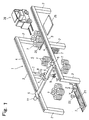
- Fig. 5 is a schematic perspective view of the tire storage
system in the second embodiment;
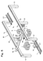
- Fig. 6 is a schematic plan view of the tire storage system
shown in Fig. 5;
- Fig. 7 is a block diagram of a control system included
in the tire storage system shown in Fig. 5;
- Fig. 8 is a layout of a tire storage system in a third
embodiment according to the present invention; and
- Fig. 9 is a layout of a tire storage system in a fourth
embodiment according to the present invention.
-
DESCRIPTION OF THE PREFERRED EMBODIMENTS
-
An intermediate tire storage system 1 in a first
embodiment according to the present invention will be described
with reference to Figs. 1 to 3. The intermediate tire storage
system 1 sorts manufactured tires T of a plurality of different
types by type and stores the tires temporarily in groups of
types. Referring to Fig. 1, a pair of longitudinal beams 3
are extended in parallel to each other and are supported
horizontally on the same level by uprights 2. Rails 4 are laid
on the longitudinal beams 3. A tire moving mechanism includes
trolleys 5 provided with wheels and capable of traveling along
the rails 4,a guide rail 6 extended between the longitudinal
beams 3 and having opposite ends connected to the trolleys 5,
respectively, a sliding unit 7 supported on the guide rail 6
for movement along the guide rail 6, a vertical shaft 8 held
on the sliding unit 7 so as to be vertically movable, and a
chuck 9 held on the lower end of the vertical shaft 8 and
provided with a plurality of holding arms 10 arranged on a
circle. The holding arms 10 can be moved simultaneously
radially outward and radially inward. The holding arms 10 of
the chuck 9 are inserted in the central hole of a tire T placed
in a horizontal position with its center axis vertically
extended and are moved radially outward so that the same are
pressed against the bead of the tire T to hold the tire T. The
holding arms 10 are moved radially inward to release the tire
T. Suppose that an X-axis is parallel to the longitudinal beam
3, a Y-axis is parallel to the guide rail 6 and a Z-axis is
vertical. Then, the chuck 9 can be moved in directions
parallel to the X-axis, the Y-axis and the Z-axis.
-
An X-axis motor 11 is mounted on one of the trolleys 5.
The X-axis motor 11 drives the wheels of the trolley 5 to move
the guide rail 6 in longitudinal directions parallel to the
X-axis. A Y-axis motor 12 is mounted on the other trolley 5
to drive the sliding unit 7 through timing-belt pulleys and
a timing belt for movement in lateral directions parallel to
the Y-axis. A Z-axis motor 13 is mounted on the sliding unit
7 to drive the vertical shaft 8 provided with a rack through
a pinion engaged with the rack for movement in vertical
directions parallel to the Z-axis. Thus, the chuck 9 is moved
in longitudinal directions parallel to the X-axis by the X-axis
motor 11, in lateral directions parallel to the Y-axis by the
Y-axis motor 12 and in vertical directions parallel to the
Z-axis by the Z-axis motor 13. The holding arms 10 of the chuck
9 are moved radially by a chuck driving motor 14 (Fig. 3).
-
A space between the pair of parallel longitudinal beams
3 is an intermediate storage yard S of the intermediate tire
storage system 1. The chuck 9 can be moved in the entire space
of the intermediate storage yard S. The unloading end of a
delivery conveyor 21 is located in a corner of the entrance
of the intermediate storage yard S. Pallets 25 are stored at
the exit of the intermediate storage yard S. When a
predetermined number of the tires T are stacked on the pallet
25, a forklift truck 26 carries the pallet 25 loaded with the
tires T to an end storage yard.
-
Fig. 3 shows a control system including a computer 30
for controlling the intermediate tire storage system 1. The
computer 30 has an XYZ coordinate map storage device 31. The
XYZ coordinate map storage device 31 stores an XYZ
coordinate map indicating positions of groups of the tires T
of different types in the intermediate storage yard S on a
coordinate system defined by the X-, the Y- and the Z-axis.
The manufactured tire T is provided with a label indicating
the type of the tire T by a bar code on its side wall at a position
near the bead. A bar-code reader 22 disposed at a position
corresponding to the middle of the delivery conveyor 21 reads
the bar code on the label to identify the type of the tire T.
The tire T may be identified in a tire size reading process
of uniformity inspection that is conducted before the tire T
is put on the delivery conveyor 21. Although the origin O of
the XYZ coordinate system may be at any position in the
intermediate storage yard S, in this embodiment, the origin
O is at the center of the tire T located at the unloading end
of the delivery conveyor 21 as shown in Figs. 1 and 2. The
sets of XYZ coordinates and the types of all the tires T stored
in the intermediate storage yard S are stored in combination
in the XYZ coordinate map storage device 31.
-
The computer 30 includes a storage position determining
device 32 that determines a storage position for an incoming
tire T delivered to the intermediate storage yard S on the basis
of data stored in the XYZ coordinate map storage device 31,
and an outgoing tire position checking device 33. Upon the
reception of a tire reception request signal from a tire
reception requesting device 40, the storage position
determining device 32 receives an identification signal
indicating a tire T to be received from the bar-code reader
22, determines a storage position for the tire T on the basis
of data stored in the XYZ coordinate map storage device 31
indicating the arrangement of tires T in the intermediate
storage yard S, and gives storage position information about
the storage position to a tire storing operation controller
34. The tire storing operation controller 34 drives the X-axis
motor 11, the Y-axis motor 12, the Z-axis motor 13 and the chuck
driving motor 14 on the basis of the storage position
information to carry the tire T delivered to the intermediate
storage yard S by the delivery conveyor 21 to a storage position
specified by the storage position information.
-
Upon the reception of a tire delivery request signal from
a tire delivery requesting device 41, the outgoing tire
position checking device 33 finds the storage position of the
tire T to be delivered on the basis of position information
about the arrangement of tires T included in the XYZ coordinate
map stored in the XYZ coordinate map storage device 31 and gives
position information about the position of the tire T to a tire
delivering operation controller 35. The tire delivering
operation controller 35 drives the X-axis motor 11, the Y-axis
motor 12, the Z-axis motor 13 and the chuck driving motor 14
on the basis of the storage position information to carry the
tire T onto the pallet 25 located at a loading position.
-
When there are tires of the same type as that of the tire
T that has been just delivered to the intermediate storage yard
S stored previously at a storage position in the intermediate
storage yard S, the tire T is stored at a storage position near
the storage position where the tires of the same type are stored
beforehand or is put on top of a stack of the previously stored
tires. When there is no tire of the same type as that of the
tire T that has been just delivered to the intermediate storage
yard S or a predetermined number of tires of the same type are
stacked in a group at a storage position, the tire T is stored
at any vacant place. Thus, the tires of the same type are stored
in a group.
-
When a tire reception request signal is provided by the
tire reception requesting device 40 and the intermediate tire
storage system 1 is in a tire receiving mode, the delivery
conveyor 21 delivers tires T of various types successively,
the bar-code reader 22 reads the bar codes on the labels
attached to the tires T, and the chuck 9 is located at a position
represented by a set of XY coordinates (0, 0) and is lowered
to a position represented by a set of XYZ coordinates (0, 0,
0). Then, the chuck 9 is inserted in the central hole of the
tire T placed in a horizontal position on the unloading end
of the delivery conveyor 21 and the holding arms 10 are moved
radially outward to hold the tire T. The chuck 9 thus holding
the tire T is raised and is moved to a position corresponding
to a position determined by the storage position determining
device 32, and the tire T is released at the same position for
storage.
-
Any special storage positions are not determined
beforehand for tires T of different types; any vacant places
are assigned to the tires T of different types to store the
tires T in groups of types. Thus, vacant places in the
intermediate storage yard S can be used for storing tires T
of any types. Thus, space can be efficiently used for storing
tires T sorted in groups by type in the intermediate storage
yard S of the smallest necessary area. Even if additional
tires T of other type need to be stored in the intermediate
storage yard S, any additional equipment does not need to be
installed and the intermediate storage yard S does not need
to be expanded and the intermediate storage yard S can be
flexibly used. Therefore any cost is not necessary to store
the additional tires of other type.
-
Tires T of the same type can be stacked up in an upright
stack by putting a tire T of the same type on top of the stack
of the tires T by locating the chuck 9 holding the tire T with
its XY coordinates coinciding with those of the center of the
stack of tires T. Therefore, the stack of tires T will not
collapse.
-
The sets of XYZ coordinates of all the tires T thus sorted
and stacked in groups of types are recorded on an XYZ coordinate
map in combination with the types of those tires T in the XYZ
coordinate map storage device 31. The Z-coordinate of the
tire T represents the height of each tire T. The upper tires
T in a stack have greater Z-coordinates, respectively.
-
The intermediate tire storage system 1 is set in a
delivery mode when the tire delivery requesting device 41
provides a tire delivery request signal. Then, the tires T
of a group are held by the chuck 9 and moved to a loading position
where the tires T are loaded onto the pallet 25. One or a
plurality of tires T of a group are moved at a time to the loading
position. When carrying a plurality of tires T of a group at
a time, the chuck 9 is lowered through the central holes of
the plurality of tires T, the holding arms 10 are moved radially
outward to hold the lowermost one of the plurality of tires
T and the chuck 9 is raised with the plurality of tires T. Thus,
the plurality of tires T can be simultaneously moved to the
pallet 25. After a predetermined number of tires T of the same
type have been loaded onto the pallet 25, the forklift truck
26 carries the pallet 25 loaded with the tires T to the end
storage yard.
-
The tire reception requesting device 40 requests the tire
receiving operation and the tire delivery requesting device
41 requests a tire delivering operation. The computer 30 may
select either the tire receiving operation or the tire
delivering operation and may control the tire reception
requesting device 40 and the tire delivery requesting device
41 accordingly or an operator may control the tire reception
requesting device 40 and the tire delivery requesting device
41 in a remote-control mode according to the condition of the
intermediate storage yard S.
-
This intermediate tire storage system 1 uses the
intermediate storage yard S for temporarily storing tires, and
the forklift truck 26 transfers the tires from the intermediate
storage yard S to the end storage yard. The intermediate
storage yard S may be used as the end storage yard or pallets
loaded with the tires may be loaded into a truck for shipping.
-
The intermediate tire storage system 1 may be provided
with two tire moving mechanisms similar to the foregoing tire
moving mechanism, and the delivery conveyor 21 may be used in
common by the two tire moving mechanism. Both the tire
receiving operation and the tire delivering operation can be
simultaneously carried out by using the two tire moving
mechanisms, which enhances the efficiency of the intermediate
tire storage system 1.
-
Although the invention has been described as applied to
the intermediate tire storage system, the present invention
is applicable to a storage system for storing products other
than tires. The storage system according to the present
invention is able to utilize space effectively and to sort and
store efficiently a large variety of products in a storage yard
of the smallest necessary area.
-
An intermediate tire storage system 51 in a second
embodiment according to the present invention will be described
with reference to Figs. 4 to 7. This intermediate tire storage
system 51 has an intermediate storage yard S for storing tires
T of different types. The tires T are supplied from the
intermediate storage yard S to a uniformity inspecting machine
U.
-
Referring to Fig. 4, a tire T conveyed by a delivery
conveyor C1 to the intermediate storage yard S is moved by a
tire moving mechanism M installed in the intermediate storage
yard S to and placed at any position in the intermediate storage
yard S for temporary storage or is transferred by the tire
moving mechanism M to a supply conveyor C2. The supply
conveyor C2 conveys the tire T to the uniformity inspecting
machine U. The uniformity inspecting machine U measures the
tire T to determine the uniformity of the tire T. The tire
T is put on a rim of a specific type conforming to the type
of the tire T on the uniformity inspecting machine U.
Therefore, only tires T of the type corresponding to that off
the rim can be inspected by the uniformity inspecting machine
U. Then inspecting tires T of a different type, the rim must
be replaced with a different rim of a type corresponding to
the type of the tires T. It is efficient to subject only tires
T of a type corresponding to that of the rim successively to
uniformity inspection.
-
Figs. 5 and 6 show the intermediate storage yard S and
the tire moving mechanism M. A pair of longitudinal beams 53
are extended in parallel to each other and are supported
horizontally on the same level by uprights 52. Rails 54 are
laid on the longitudinal beams 53. A tire moving mechanism
includes trolleys 55 provided with wheels and capable of
traveling along the rails 54,a guide rail 56 extended between
the longitudinal beams 53 and having opposite ends connected
to the trolleys 55, respectively, a sliding unit 57 supported
on the guide rail 56 for movement along the guide rail 56, a
vertical shaft 58 held on the sliding unit 57 so as to be
vertically movable, and a chuck 59 held on the lower end of
the vertical shaft 58 and provided with a plurality of holding
arms 60 arranged on a circle. The holding arms 60 can be moved
simultaneously radially outward and radially inward. The
holding arms 60 of the chuck 59 are inserted in the central
hole of a tire T placed in a horizontal position with its center
axis vertically extended and are moved radially outward so that
the same are pressed against the bead of the tire T to hold
the tire T. The holding arms 60 are moved radially inward to
release the tire T. Suppose that an X-axis is parallel to the
longitudinal beam 53, a Y-axis is parallel to the guide rail
56 and a Z-axis is vertical. Then, the chuck 59 can be moved
in directions parallel to the X-axis, the Y-axis and the Z-axis.
-
An X-axis motor 61 is mounted on one of the trolleys 55.
The X-axis motor 61 drives the wheels of the trolley 5 to move
the guide rail 56 in longitudinal directions parallel to the
X-axis. A Y-axis motor 62 is mounted on the other trolley 5
to drive the sliding unit 57 through timing-belt pulleys and
a timing belt for movement in lateral directions parallel to
the Y-axis. A Z-axis motor 63 is mounted on the sliding unit
57 to drive the vertical shaft 58 provided with a rack through
a pinion engaged with the rack for movement in vertical
directions parallel to the Z-axis. Thus, the chuck 59 is moved
in longitudinal directions parallel to the X-axis by the X-axis
motor 61, in lateral directions parallel to the Y-axis by the
Y-axis motor 62 and in vertical directions parallel to the
Z-axis by the Z-axis motor 63. The holding arms 60 of the chuck
59 are moved radially by a chuck driving motor 64, not shown
in Fig. 5.
-
A space between the pair of parallel longitudinal beams
53 is an intermediate storage yard S of the intermediate tire
storage system 51. The chuck 59 can be moved in the entire
space of the intermediate storage yard S. A delivery conveyor
C1 is disposed with its unloading end located in a corner of
the entrance of the intermediate storage yard S. A supply
conveyor C2 is disposed with its loading end located in a corner
of the exit of the intermediate storage yard S.
-
Fig. 7 shows a control system including a computer 80
for controlling the intermediate tire storage system 51. The
computer 80 has a delivery conveyor controller 88 for
controlling the delivery conveyor C1, a supply conveyor
controller 89 for controlling the supply conveyor C2, and an
XYZ coordinate map storage device 81 storing an XYZ coordinate
map including sets of XYZ coordinates indicating positions of
tires T of different types in the intermediate storage yard
S on a coordinate system defined by the X-, the Y- and the Z-axis.
The sets of XYZ coordinates and the types of all the tires T
stored in the intermediate storage yard S are stored in
combination in the XYZ coordinate map storage device 81. The
manufactured tire T is provided with a label indicating the
type of the tire T by a bar code on its side wall at a position
near the bead. A bar-code reader 72 disposed at a position
corresponding to the middle of the delivery conveyor C1 reads
the bar code on the label to identify the type of the tire T.
A type identifying device 86 identifies the type of the tire
T. Information about the tire T including size may be read
while the tire T is on the delivery conveyor C1 or before the
tire T is placed onto the delivery conveyor C1.
-
Although the origin O of the XYZ coordinate system may
be at any position in the intermediate storage yard S, in this
embodiment, the origin O is at the center of the tire T located
at the unloading end of the delivery conveyor C1 as shown in
Figs. 5 and 6.
-
The sets of XYZ coordinates indicating the positions of
the tires T stored in the intermediate storage yard S and the
types of the same are stored in combination in the XYZ
coordinate map storage device 81.
-
The computer 80 includes a storage position determining
device 82 that determines a storage position for an incoming
tire T delivered to the intermediate storage yard S on the basis
of data stored in the XYZ coordinate map storage device 81,
and an outgoing tire position checking device 83.
-
The bar-code reader 72 gives tire information about a
tire including the type of the tire to the computer 80 and a
rim information input device 90 gives rim information including
the size of the rim used at present on the uniformity inspecting
machine U to the computer 80. The bar-code reader 72 gives
tire information to the type identifying device 86. A tire
selecting device 87 compares the rim information and the tire
information to decide whether the tire is of the type
corresponding to the type of the rim used at present on the
uniformity inspecting machine U. The tire is sent directly
to the uniformity inspecting machine U when the type of the
tire corresponds to that of the rim or is stored in the
intermediate storage yard S when the type of the tire does not
correspond to that of the rim.
-
Upon the reception of a storage signal requesting the
storage of the tire T from the tire selecting device 87, a
storage position determining device 82 decides a position where
the tire T is to be stored on the basis of tire information
including the type of the tire T and the arrangement of tires
T represented by the XYZ coordinate map stored in the XYZ
coordinate map storage device 81 and gives information about
a storage position for the tire T to a tire storing operation
controller 84. The tire storing operation controller 84
drives the X-axis motor 61, the Y-axis motor 62, the Z-axis
motor 63 and the chuck driving motor 64 on the basis of the
storage position information to carry the tire T delivered to
the intermediate storage yard S by the delivery conveyor C1
to a storage position specified by the storage position
information. When there are tires of the same type as that
of the tire T that has been just delivered to the intermediate
storage yard S stored previously at a storage position in the
intermediate storage yard S, the tire T is stored at a storage
position near the storage position where the tires of the same
type are stored beforehand or is put on top of a stack of the
previously stored tires. When there is no tire of the same
type as that of the tire T that has been just delivered to the
intermediate storage yard S or a predetermined number of tires
of the same type are stacked in a group at a storage position,
the tire T is stored at any vacant place. Thus, the tires of
the same type are stored in a group.
-
The delivery conveyor controller 88 drives the delivery
conveyor C1 to deliver tires T of various types successively,
the bar-code reader 72 reads the bar codes on the labels
attached to the tires T, and the chuck 9 is located at a position
represented by a set of XY coordinates (0, 0) and is lowered
to a position represented by a set of XYZ coordinates (0, 0,
0). Then, the chuck 9 is inserted in the central hole of the
tire T placed in a horizontal position on the unloading end
of the delivery conveyor C1 and the holding arms 60 are moved
radially outward to hold the tire T. The chuck 9 thus holding
the tire T is raised and is moved to a position corresponding
to a position determined by the storage position determining
device 82, and the tire T is released at the same position for
storage.
-
Any special storage positions are not determined
beforehand for tires T of different types; any vacant places
are assigned to the tires T of different types to store the
tires T in groups of types. Thus, vacant places in the
intermediate storage yard S can be used for storing tires T
of any types. Thus, space can be efficiently used for storing
tires T sorted in groups by type in the intermediate storage
yard S of the smallest necessary area.
-
When the tire selecting device 87 decides that the tire
T that has been just delivered by the delivery conveyor C1 to
the intermediate storage yard S is of a type corresponding to
that of the rim being used at present on the uniformity
inspecting machine U and can be inspected by the uniformity
inspecting machine U, the tire selecting device 87 gives a tire
supply signal to a tire supply operation controller 85. Then,
the tire supply operation controller 85 drives the X-axis motor
61, the Y-axis motor 62, the Z-axis motor 63 and the chuck
driving motor 64 to pick up the tire T from the delivery conveyor
C1 and to transfer the tire T to the supply conveyor C2. When
the tire T is loaded onto the supply conveyor C2, the supply
conveyor controller 89 droves the supply conveyor C2 to supply
the tire T to the uniformity inspecting machine U. The tire
T is put on the rim and is subjected to uniformity inspection.
-
As mentioned above, the tires T of types not
corresponding to that of the rim delivered to the intermediate
storage yard S are stacked in groups of types at optional
positions in the intermediate storage yard S for temporary
storage, while the tires T of types corresponding to that of
the rim delivered to the intermediate storage yard S are loaded
onto the supply conveyors C2, and the supply conveyors C2
conveys those tires T to the uniformity inspecting machine U.
These operations are carried out completely automatically
without requiring any manual operations, so that the tires T
can be efficiently supplied to the uniformity inspecting
machine U. When the rim being used on the uniformity
inspecting machine U is replaced with a different one to start
inspecting tires of a different type, the rim information input
device 90 enters rim information about the different rim into
the computer 80. Then, the tire identifying device 86
identifies the types of tires T delivered by the delivery
conveyor C1 to the intermediate storage yard S, the tire
selecting device 87 discriminates between tires T to be
supplied to the uniformity inspecting machine U and those to
be stored temporarily in the intermediate storage yard S. The
tires to be supplied to the uniformity inspecting machine U
are supplied to the uniformity inspecting machine U and those
to be stored are stored temporarily in the intermediate storage
yard S.
-
When the rim is replaced with the a different one and
tires T of a type corresponding to that of the different rim
are stored in the intermediate storage yard S, the outgoing
tire position checking device 83 receives rim information from
the rim information input device 90 finds the position of the
tires T of a type corresponding to that of the different rim
on the basis of the position information included in the XYZ
coordinate map stored in the XYZ coordinate map storage device
81, and gives position information about the position of the
tires T to the tire supply operation controller 85. The tire
supply operation controller 85 drives the X-axis motor 61, the
Y-axis motor 62, the Z-axis motor 63 and the chuck driving motor
64 to pick up the tire T from the delivery conveyor C1 and to
transfer the tire T to the supply conveyor C2. Then, the supply
conveyor controller 89 drives the supply conveyor C2 to supply
the tire T to the uniformity inspecting machine U. When tires
T of a type corresponding to that of the rim are stored in the
intermediate storage yard S and tires T of the same type are
delivered additionally to the intermediate storage yard S, the
tire T near the chuck 59 may be preferentially moved to the
supply conveyor C2. Even if additional tires T of other type
are delivered to the intermediate storage yard S, any
additional equipment does not need to be installed and the
intermediate storage yard S does not need to be expanded and
the intermediate storage yard S can be flexibly used.
Therefore any cost is not necessary to store the additional
tires of other type.
-
Tires T of the same type can be stacked up in an upright
stack by putting a tire T of the same type on top of the stack
of the tires T by locating the chuck 59 holding the tire T with
its XY coordinates coinciding with those of the center of the
stack of tires T. Therefore, the stack of tires T will not
collapse.
-
The sets of XYZ coordinates of all the tires T thus sorted
and stacked in groups of types are recorded on an XYZ coordinate
map in combination with the types of those tires T in the XYZ
coordinate map storage device 81. The Z-coordinate of the
tire T represents the height of each tire T. The upper tires
T in a stack have greater Z-coordinates, respectively.
-
A tire storage system in a third embodiment according
to the present invention will be described with reference to
Fig. 8. This tire storage system supplies a tire T of a type
corresponding to that of a rim being used on a uniformity
inspecting machine U directly to the uniformity inspecting
machine U. A delivery conveyor C3 is extended to the
uniformity inspecting machine U to supply a tire T directly
to the uniformity inspecting machine U. Intermediate storage
yards S are disposed on the opposite sides of a middle section
of the delivery conveyor C3. The intermediate storage yards
S are provided with tire moving mechanisms M, respectively.
The tire moving mechanisms M are the same as those of the
foregoing embodiments. Each tire moving mechanism M is
capable of picking up a tire T from the delivery conveyor C3,
of moving the tire T to a desired position and of putting a
tire on the delivery conveyor C3. The type of a tire T conveyed
by the delivery conveyor C3 is identified before the tire T
reaches a position corresponding to the intermediate storage
yards S. A tire T of a type corresponding to that of the rim
being used on the uniformity inspecting machine U is conveyed
straight to the uniformity inspecting machine U without
stopping at a place corresponding to the intermediate storage
yards S and is subjected to uniformity inspection. A tire T
of a type not corresponding to that of the rim being used on
the uniformity inspecting machine U is stopped at a place
between the intermediate storage yards S and is removed from
the delivery conveyor C3 by the tire moving mechanism M of
either of the intermediate storage yards S. Thus, the tires
T removed from delivery conveyor C3 are sorted and stored
temporarily in groups of types at any positions in the
intermediate storage yards S.
-
When the rim on the uniformity inspecting machine U is
replaced with a different one of a different type for inspecting
tires T of other type, the tires T of other type are put on
the delivery conveyor C3 by the tire moving mechanism M and
are supplied to the uniformity inspecting machine U for
uniformity inspection. Thus, the tires can be efficiently
supplied to the uniformity inspecting machine U without using
any manual labor. Since the tires other than those that are
to be supplied to the tire inspecting machine U can be stored
in groups of types in any vacant places in the intermediate
storage yard S which are not assigned specially to any special
groups, space can be efficiently used and the tires can be
sorted and stored in groups of types in the storage yard S of
the smallest necessary area.
-
A tire storage system in a fourth embodiment according
to the present invention will be described with reference to
Fig. 9. A delivery conveyor C5 for conveying tires T to a
uniformity inspecting machine U is provided with two transfer
conveyors C6 and C7. A first roundabout conveyor C8 extends
between the upstream transfer conveyor C6 and an intermediate
storage yard S, and a second roundabout conveyor C9 extends
between the intermediate storage yard S and the downstream
transfer conveyor C7. The type of a tire T conveyed by the
delivery conveyor C5 is identified previously. If the type
of the tire T corresponds to that of a rim in use on the
uniformity inspecting machine U, the tire T is supplied
straight to the uniformity inspecting machine U by the delivery
conveyor C5. If the type of the tire T does not correspond
to that of the rim, is transferred from the delivery conveyor
C5 to the roundabout conveyor C8 by the transfer conveyor C6
and is conveyed to the intermediate storage yard S. The tire
T is held and moved by a tire moving mechanism M and placed
at any vacant position in the intermediate storage yard S.
Thus, tires of types not corresponding to that of the rim are
sorted and stored temporarily in groups of types at any vacant
positions in the intermediate storage yard S.
-
When the rim on the uniformity inspecting machine U is
replaced with a different one to inspect the tires T of a type
corresponding to that of the different rim stored in the
intermediate storage yard S, the tires T are put on the second
roundabout conveyor C9, the second roundabout conveyor C9
conveys the tires T to the transfer conveyor C7 and the transfer
conveyor C7 transfers the tires T from the second roundabout
conveyor C9 to the delivery conveyor C5. Then the delivery
conveyor C5 delivers the tires T to the uniformity inspecting
machine U for uniformity inspection. Thus, the tires T can
be efficiently supplied to the uniformity inspecting machine
U without using manual labor. Since the tires are stored in
groups of types at any vacant places which are not assigned
specially to any special groups, space can be efficiently used
and the tires can be stored in groups of types in the storage
yard S of the smallest necessary area.
-
Although the invention has been described in its
preferred embodiments with a certain degree of particularity,
obviously many changes and variations are possible therein.
It is therefore to be understood that the present invention
may be practiced otherwise than as specifically describe herein
without departing from the scope and spirit thereof.