EP1057737B1 - Improved container with handle and manufacturing method - Google Patents
Improved container with handle and manufacturing method Download PDFInfo
- Publication number
- EP1057737B1 EP1057737B1 EP00401566A EP00401566A EP1057737B1 EP 1057737 B1 EP1057737 B1 EP 1057737B1 EP 00401566 A EP00401566 A EP 00401566A EP 00401566 A EP00401566 A EP 00401566A EP 1057737 B1 EP1057737 B1 EP 1057737B1
- Authority
- EP
- European Patent Office
- Prior art keywords
- handle
- ring
- internal edge
- rolled
- container
- Prior art date
- Legal status (The legal status is an assumption and is not a legal conclusion. Google has not performed a legal analysis and makes no representation as to the accuracy of the status listed.)
- Expired - Lifetime
Links
- 238000004519 manufacturing process Methods 0.000 title claims description 5
- 239000002184 metal Substances 0.000 claims abstract description 9
- 238000007373 indentation Methods 0.000 abstract description 3
- 238000004806 packaging method and process Methods 0.000 description 25
- 208000031968 Cadaver Diseases 0.000 description 6
- 238000000034 method Methods 0.000 description 3
- 238000005034 decoration Methods 0.000 description 2
- 230000005489 elastic deformation Effects 0.000 description 1
- 239000000463 material Substances 0.000 description 1
- 230000002093 peripheral effect Effects 0.000 description 1
- 238000004064 recycling Methods 0.000 description 1
- 230000000284 resting effect Effects 0.000 description 1
- 238000007789 sealing Methods 0.000 description 1
- 238000003466 welding Methods 0.000 description 1
Images


Classifications
-
- B—PERFORMING OPERATIONS; TRANSPORTING
- B65—CONVEYING; PACKING; STORING; HANDLING THIN OR FILAMENTARY MATERIAL
- B65D—CONTAINERS FOR STORAGE OR TRANSPORT OF ARTICLES OR MATERIALS, e.g. BAGS, BARRELS, BOTTLES, BOXES, CANS, CARTONS, CRATES, DRUMS, JARS, TANKS, HOPPERS, FORWARDING CONTAINERS; ACCESSORIES, CLOSURES, OR FITTINGS THEREFOR; PACKAGING ELEMENTS; PACKAGES
- B65D21/00—Nestable, stackable or joinable containers; Containers of variable capacity
- B65D21/02—Containers specially shaped, or provided with fittings or attachments, to facilitate nesting, stacking, or joining together
- B65D21/0209—Containers specially shaped, or provided with fittings or attachments, to facilitate nesting, stacking, or joining together stackable or joined together one-upon-the-other in the upright or upside-down position
- B65D21/023—Closed containers provided with local cooperating elements in the top and bottom surfaces, e.g. projection and recess
-
- B—PERFORMING OPERATIONS; TRANSPORTING
- B65—CONVEYING; PACKING; STORING; HANDLING THIN OR FILAMENTARY MATERIAL
- B65D—CONTAINERS FOR STORAGE OR TRANSPORT OF ARTICLES OR MATERIALS, e.g. BAGS, BARRELS, BOTTLES, BOXES, CANS, CARTONS, CRATES, DRUMS, JARS, TANKS, HOPPERS, FORWARDING CONTAINERS; ACCESSORIES, CLOSURES, OR FITTINGS THEREFOR; PACKAGING ELEMENTS; PACKAGES
- B65D25/00—Details of other kinds or types of rigid or semi-rigid containers
- B65D25/28—Handles
- B65D25/32—Bail handles, i.e. pivoted rigid handles of generally semi-circular shape with pivot points on two opposed sides or wall parts of the conainter
-
- B—PERFORMING OPERATIONS; TRANSPORTING
- B65—CONVEYING; PACKING; STORING; HANDLING THIN OR FILAMENTARY MATERIAL
- B65D—CONTAINERS FOR STORAGE OR TRANSPORT OF ARTICLES OR MATERIALS, e.g. BAGS, BARRELS, BOTTLES, BOXES, CANS, CARTONS, CRATES, DRUMS, JARS, TANKS, HOPPERS, FORWARDING CONTAINERS; ACCESSORIES, CLOSURES, OR FITTINGS THEREFOR; PACKAGING ELEMENTS; PACKAGES
- B65D43/00—Lids or covers for rigid or semi-rigid containers
- B65D43/02—Removable lids or covers
- B65D43/0202—Removable lids or covers without integral tamper element
- B65D43/0214—Removable lids or covers without integral tamper element secured only by friction or gravity
- B65D43/022—Removable lids or covers without integral tamper element secured only by friction or gravity only on the inside, or a part turned to the inside, of the mouth of the container
-
- B—PERFORMING OPERATIONS; TRANSPORTING
- B65—CONVEYING; PACKING; STORING; HANDLING THIN OR FILAMENTARY MATERIAL
- B65D—CONTAINERS FOR STORAGE OR TRANSPORT OF ARTICLES OR MATERIALS, e.g. BAGS, BARRELS, BOTTLES, BOXES, CANS, CARTONS, CRATES, DRUMS, JARS, TANKS, HOPPERS, FORWARDING CONTAINERS; ACCESSORIES, CLOSURES, OR FITTINGS THEREFOR; PACKAGING ELEMENTS; PACKAGES
- B65D2543/00—Lids or covers essentially for box-like containers
- B65D2543/00009—Details of lids or covers for rigid or semi-rigid containers
- B65D2543/00018—Overall construction of the lid
- B65D2543/00064—Shape of the outer periphery
- B65D2543/00074—Shape of the outer periphery curved
- B65D2543/00092—Shape of the outer periphery curved circular
-
- B—PERFORMING OPERATIONS; TRANSPORTING
- B65—CONVEYING; PACKING; STORING; HANDLING THIN OR FILAMENTARY MATERIAL
- B65D—CONTAINERS FOR STORAGE OR TRANSPORT OF ARTICLES OR MATERIALS, e.g. BAGS, BARRELS, BOTTLES, BOXES, CANS, CARTONS, CRATES, DRUMS, JARS, TANKS, HOPPERS, FORWARDING CONTAINERS; ACCESSORIES, CLOSURES, OR FITTINGS THEREFOR; PACKAGING ELEMENTS; PACKAGES
- B65D2543/00—Lids or covers essentially for box-like containers
- B65D2543/00009—Details of lids or covers for rigid or semi-rigid containers
- B65D2543/00018—Overall construction of the lid
- B65D2543/00259—Materials used
- B65D2543/00296—Plastic
-
- B—PERFORMING OPERATIONS; TRANSPORTING
- B65—CONVEYING; PACKING; STORING; HANDLING THIN OR FILAMENTARY MATERIAL
- B65D—CONTAINERS FOR STORAGE OR TRANSPORT OF ARTICLES OR MATERIALS, e.g. BAGS, BARRELS, BOTTLES, BOXES, CANS, CARTONS, CRATES, DRUMS, JARS, TANKS, HOPPERS, FORWARDING CONTAINERS; ACCESSORIES, CLOSURES, OR FITTINGS THEREFOR; PACKAGING ELEMENTS; PACKAGES
- B65D2543/00—Lids or covers essentially for box-like containers
- B65D2543/00009—Details of lids or covers for rigid or semi-rigid containers
- B65D2543/00435—Lids secured to an intermediate ring or like annular member fixed to the container mouth
-
- B—PERFORMING OPERATIONS; TRANSPORTING
- B65—CONVEYING; PACKING; STORING; HANDLING THIN OR FILAMENTARY MATERIAL
- B65D—CONTAINERS FOR STORAGE OR TRANSPORT OF ARTICLES OR MATERIALS, e.g. BAGS, BARRELS, BOTTLES, BOXES, CANS, CARTONS, CRATES, DRUMS, JARS, TANKS, HOPPERS, FORWARDING CONTAINERS; ACCESSORIES, CLOSURES, OR FITTINGS THEREFOR; PACKAGING ELEMENTS; PACKAGES
- B65D2543/00—Lids or covers essentially for box-like containers
- B65D2543/00009—Details of lids or covers for rigid or semi-rigid containers
- B65D2543/00444—Contact between the container and the lid
- B65D2543/00481—Contact between the container and the lid on the inside or the outside of the container
- B65D2543/0049—Contact between the container and the lid on the inside or the outside of the container on the inside, or a part turned to the inside of the mouth of the container
- B65D2543/00509—Cup
-
- B—PERFORMING OPERATIONS; TRANSPORTING
- B65—CONVEYING; PACKING; STORING; HANDLING THIN OR FILAMENTARY MATERIAL
- B65D—CONTAINERS FOR STORAGE OR TRANSPORT OF ARTICLES OR MATERIALS, e.g. BAGS, BARRELS, BOTTLES, BOXES, CANS, CARTONS, CRATES, DRUMS, JARS, TANKS, HOPPERS, FORWARDING CONTAINERS; ACCESSORIES, CLOSURES, OR FITTINGS THEREFOR; PACKAGING ELEMENTS; PACKAGES
- B65D2543/00—Lids or covers essentially for box-like containers
- B65D2543/00009—Details of lids or covers for rigid or semi-rigid containers
- B65D2543/00444—Contact between the container and the lid
- B65D2543/00481—Contact between the container and the lid on the inside or the outside of the container
- B65D2543/00537—Contact between the container and the lid on the inside or the outside of the container on the outside, or a part turned to the outside of the mouth of the container
- B65D2543/00546—NO contact
Definitions
- the present invention relates to a packaging with an improved handle and a manufacturing process of this packaging.
- the subject of the invention is a packaging of the above type, characterized in that the handle is mounted articulated on the ring, each pin being, on the one hand, axially immobilized by fitting between the internal rolled edge of the ring and the part center of this ring, and on the other hand, angularly immobilized around the axis of revolution of the body by nesting in a recess formed on the internal edge rolled of the ring.
- FIG. 1 There is shown in Figures 1 and 2 a package according to the invention, designated by the general reference 10.
- the package 10 comprises a metal body 12, of general shape revolution, for example cylindrical, provided with an upper end 14, access to the interior of the packaging, and a lower end 16 carrying a bottom 18.
- the body is generally provided with a decoration on its external surface.
- the package 10 also includes a metal ring 20 provided with an edge outer 20E set on the upper end 14 of the body and an inner edge 20I defining an opening 22 for access to the interior of the packaging. Note that the internal edge 20I of the ring is rolled towards the outside of the opening 22.
- the inner 20I and outer 20E edges of the ring are separated by a part annular center 20C of this ring extending substantially radially from the periphery of the body 12 towards the axis X of revolution of this body 12.
- This central part 20C comprises a step D separating an upper part 20 CH from a lower part 20CB.
- the opening 22 is closable, in a manner known per se, by means of a cover reentrant classic 24. If necessary, the cover 24 can be provided with a seal rubber sealing.
- the package 10 also includes a handle 26, preferably metallic, provided of curved ends, forming pins 26E mounted articulated on the ring 20.
- the handle 26 is movable between an upright gripping position, such as shown in Figure 1, and a folded position towards the ring 20, as shown in Figures 2 and 3. In its gripping position, the handle 26 is substantially parallel to a diametrical plane P of the body 12. In its folded position, the handle 26 is substantially perpendicular to the diametrical plane P.
- each pin 26E of the handle is immobilized axially and angularly around the X axis by material means with the ring 20.
- each pin 26E is, on the one hand, immobilized axially by interlocking between the internal rolled edge 20I of the ring and the central part 20C of this ring, and on the other hand, angularly immobilized around the X axis, by fitting in a recess 28 formed on the internal rolled edge 20I of the ring (see in particular Figures 1 and 2).
- the pins 26E of the handle are opposite inclination with respect to a plane Q of symmetry of the loop 26 in parallel which is curved this loop 26 (the plane Q substantially coincides with the plane P when the handle 26 is in its upright gripping position).
- the handle 26 In the folded position, the handle 26 is inserted radially between the edges internal 20I and external 20E of the ring 20 (see FIG. 2).
- the handle 26 in position folded down does not partially hide the external decoration of the body 12, as is observed on the other hand on conventional packaging fitted with a foldable handle against their external surface.
- the part 26I of the intermediate handle between the pins 26E is slightly separated from the central part 20C of the ring, above this central part 20C, due to the opposite inclinations of the pins 26E (see figure 3).
- This difference between the intermediate part 26I of the handle and the central part 20C of the ring facilitates gripping of the handle when it is in the folded position, in order to allow the movement of this handle towards its upright position.
- This package intermediate comprises the body 12 and the ring 20 set on the upper end 14 of this body.
- the ring 20 is provided with its internal edge 20I which is not yet completely rolled out.
- the pins are placed 26E of the handle 26 resting on the central part 20C of the ring 20.
- the internal edge 201 of the ring is completely rolled up so that the indentations 28 are formed by deformation of this internal edge 20I in contact with the pins 20E.
- the indentations 28 have as their alignment plane the diametrical plane P of the body 12.
- the bottom 18 of the packaging is provided with a peripheral edge 18E, crimped onto the lower end 16 of the body 12, and of a central part 18C, set back towards the upper end 14 of the body 12 relative to this crimped edge 18E.
- the end lower 16 is formed by a constriction of the body 12. This allows the stacking of two identical packages 10 as shown in FIG. 3. Indeed, the part central set back 18C from the bottom of the upper packaging forms a clearance in which extends, at least partially, the cover 24 and possibly the internal edge 20I of the ring of the lower packaging.
- the lower edge 16 of the body of the upper package bears directly on the annular central part 20C of the ring 20 of the packaging inferior.
- intermediate part 26I of the handle of the lower packaging which possibly protrudes slightly above the cover 24 of the lower packaging, is likely to flatten by elastic deformation in contact with the bottom 18 of the upper packaging, so as not to interfere with the stacking of the two packages.
- the body of the package is not necessarily cylindrical but can be frustoconical, the upper end of the body having a diameter greater than that of the lower end of this body.
- the handle can be hung on the ring crimped on the body of the packaging without using an additional part which limits the price of returns from the packaging.
- the folded handle does not limit the possibilities of stacking identical packaging.
- the method of mounting the handle on the ring is simple and easy to automate. This process avoids the usual operations of welding or re-varnishing imposed by classic techniques of mounting a handle on a body metal packaging.
- the packaging can be entirely metallic which facilitates its recycling.
Abstract
Description
La présente invention concerne un emballage à anse perfectionnée et un procédé de fabrication de cet emballage.The present invention relates to a packaging with an improved handle and a manufacturing process of this packaging.
On connaít déjà dans l'état de la technique un emballage du type comprenant
L'invention a pour objet un emballage du type précité, caractérisé en ce que l'anse est montée articulée sur la bague, chaque tourillon étant, d'une part, immobilisé axialement par emboítement entre le bord roulé interne de la bague et la partie centrale de cette bague, et d'autre part, immobilisé angulairement autour de l'axe de révolution du corps par emboítement dans un enfoncement ménagé sur le bord interne roulé de la bague.The subject of the invention is a packaging of the above type, characterized in that the handle is mounted articulated on the ring, each pin being, on the one hand, axially immobilized by fitting between the internal rolled edge of the ring and the part center of this ring, and on the other hand, angularly immobilized around the axis of revolution of the body by nesting in a recess formed on the internal edge rolled of the ring.
Suivant d'autres caractéristiques de cet emballage :
- les tourillons sont inclinés de façon opposée par rapport à un plan de symétrie de l'anse parallèlement auquel s'incurve l'anse ;
- l'anse est déplaçable entre une position dressée de préhension, dans laquelle cette anse est sensiblement parallèle à un plan diamétral du corps, et une position rabattue vers la bague, dans laquelle cette anse est sensiblement perpendiculaire au plan diamétral ; et
- l'anse est métallique.
- the pins are inclined in an opposite manner with respect to a plane of symmetry of the handle parallel to which the handle curves;
- the handle is movable between an upright gripping position, in which this handle is substantially parallel to a diametral plane of the body, and a position folded towards the ring, in which this handle is substantially perpendicular to the diametral plane; and
- the handle is metallic.
L'invention a également pour objet un procédé de fabrication d'un emballage tel que défini ci-dessus, caractérisé en ce que
- on forme un emballage intermédiaire comportant le corps et la bague sertie sur l'extrémité supérieure de ce corps,
- on place les tourillons de l'anse en appui sur la partie centrale de la bague,
- on roule le bord interne de la bague de façon que les enfoncements se forment par déformation de ce-bord interne au contact des tourillons.
- an intermediate packaging is formed comprising the body and the ring crimped on the upper end of this body,
- the pins of the handle are placed in abutment on the central part of the ring,
- the internal edge of the ring is rolled so that the depressions are formed by deformation of this internal edge in contact with the pins.
L'invention sera mieux comprise à la lecture de la description qui va suivre donnée uniquement à titre d'exemple et faite en se référant aux dessins dans lesquels :
- la figure 1 est une vue en élévation, en coupe axiale, d'un emballage selon l'invention, l'anse étant dans sa position dressée de préhension et l'extrémité supérieure du corps étant fermée par un couvercle ;
- la figure 2 est une vue de dessus de l'emballage représenté à la figure 1, l'anse étant dans sa position rabattue et le couvercle étant retiré ;
- la figure 3 est une demi-vue en coupe axiale de deux emballages identiques à celui de la figure 1 gerbés l'un sur l'autre ;
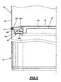
- la figure 4 est une vue de détail de la partie cerclée 4 de la figure 1 montrant une étape de montage de l'anse sur la bague de l'emballage;
- la figure 5 est une vue de l'anse suivant la flèche 5 de la figure 1.
- Figure 1 is an elevational view, in axial section, of a package according to the invention, the handle being in its upright gripping position and the upper end of the body being closed by a cover;
- Figure 2 is a top view of the package shown in Figure 1, the handle being in its folded position and the cover being removed;
- Figure 3 is a half view in axial section of two packages identical to that of Figure 1 stacked one on the other;
- Figure 4 is a detail view of the circled
part 4 of Figure 1 showing a step of mounting the handle on the ring of the package; - FIG. 5 is a view of the handle according to arrow 5 in FIG. 1.
On a représenté sur les figures 1 et 2 un emballage selon l'invention, désigné
par la référence générale 10. There is shown in Figures 1 and 2 a package according to the invention, designated
by the
L'emballage 10 comporte un corps métallique 12, de forme générale de
révolution, par exemple cylindrique, muni d'une extrémité supérieure 14, d'accès à
l'intérieur de l'emballage, et d'une extrémité inférieure 16 portant un fond 18. Le corps est
en général muni d'un décor sur sa surface externe.The
L'emballage 10 comporte également une bague métallique 20 munie d'un bord
externe 20E serti sur l'extrémité supérieure 14 du corps et d'un bord interne 20I délimitant
une ouverture 22 d'accès à l'intérieur de l'emballage. On notera que le bord interne 20I de
la bague est roulé vers l'extérieur de l'ouverture 22.The
Les bords interne 20I et externe 20E de la bague sont séparés par une partie
centrale annulaire 20C de cette bague s'étendant sensiblement radialement depuis la
périphérie du corps 12 vers l'axe X de révolution de ce corps 12. Cette partie centrale 20C
comporte un décrochement D séparant une partie haute 20 CH d'une partie basse 20CB.The inner 20I and outer 20E edges of the ring are separated by a part
L'ouverture 22 est obturable, de façon connue en soi, au moyen d'un couvercle
rentrant classique 24. Le cas échéant, le couvercle 24 peut être muni d'un joint
d'étanchéité en caoutchouc.The opening 22 is closable, in a manner known per se, by means of a cover
reentrant classic 24. If necessary, the
L'emballage 10 comporte encore une anse 26, de préférence métallique, munie
d'extrémités recourbées, formant des tourillons 26E montés articulés sur la bague 20.The
L'anse 26 est déplaçable entre une position dressée de préhension, telle que
représentée sur la figure 1, et une position rabattue vers la bague 20, telle que représentée
sur les figures 2 et 3. Dans sa position de préhension, l'anse 26 est sensiblement parallèle
à un plan diamétral P du corps 12. Dans sa position rabattue, l'anse 26 est sensiblement
perpendiculaire au plan diamétral P.The
Les tourillons 26E de l'anse sont immobilisés axialement et angulairement
autour de l'axe X par des moyens venus de matière avec la bague 20. Ainsi, dans
l'exemple illustré, chaque tourillon 26E est, d'une part, immobilisé axialement par
emboítement entre le bord roulé interne 20I de la bague et la partie centrale 20C de cette
bague, et d'autre part, immobilisé angulairement autour de l'axe X, par emboítement dans
un enfoncement 28 ménagé sur le bord interne roulé 20I de la bague (voir notamment
figures 1 et 2). On notera, en se référant à la figure 5, que les tourillons 26E de l'anse sont
inclinés de façon opposée par rapport à un plan Q de symétrie de l'anse 26 parallèlement
auquel s'incurve cette anse 26 (le plan Q coïncide sensiblement avec le plan P lorsque
l'anse 26 est dans sa position dressée de préhension). The
En position rabattue, l'anse 26 est intercalée radialement entre les bords
interne 20I et externe 20E de la bague 20 (voir figure 2). Ainsi, l'anse 26 en position
rabattue ne masque pas partiellement le décor externe du corps 12, comme cela est
observé par contre sur les emballages classiques munis d'une anse rabattable contre leur
surface externe.In the folded position, the
Par ailleurs, en position rabattue, la partie 26I de l'anse intermédiaire entre les
tourillons 26E est légèrement écartée de la partie centrale 20C de la bague, au-dessus de
cette partie centrale 20C, du fait des inclinaisons opposées des tourillons 26E (voir figure
3). Cet écart entre la partie intermédiaire 26I de l'anse et la partie centrale 20C de la
bague facilite la préhension de l'anse lorsque celle-ci est en position rabattue, afin de
permettre le déplacement de cette anse vers sa position dressée.Furthermore, in the folded position, the part 26I of the intermediate handle between the
Pour fabriquer l'emballage 10 représenté sur la figure 1, on forme tout
d'abord un emballage intermédiaire 10I tel que représenté sur la figure 4. Cet emballage
intermédiaire comporte le corps 12 et la bague 20 sertie sur l'extrémité supérieure 14 de
ce corps. La bague 20 est munie de son bord interne 20I qui n'est pas encore
complètement roulé vers l'extérieur.To manufacture the
Après avoir fabriqué cet emballage intermédiaire 10I, on place les tourillons
26E de l'anse 26 en appui sur la partie centrale 20C de la bague 20.After having manufactured this intermediate packaging 10I, the pins are placed
26E of the
Puis, on roule complètement le bord interne 201 de la bague de façon que les
enfoncements 28 se forment par déformation de ce bord interne 20I au contact des
tourillons 20E. Les enfoncements 28 ont pour plan d'alignement le plan diamétral P du
corps 12.Then, the
Le fond 18 de l'emballage est muni d'un bord périphérique 18E, serti sur
l'extrémité inférieure 16 du corps 12, et d'une partie centrale 18C, en retrait vers
l'extrémité supérieure 14 du corps 12 par rapport à ce bord serti 18E. L'extrémité
inférieure 16 est formée par un retreint du corps 12. Ceci permet le gerbage de deux
emballages 10 identiques comme cela est représenté sur la figure 3. En effet, la partie
centrale en retrait 18C du fond de l'emballage supérieur forme un dégagement dans lequel
s'étend, au moins partiellement, le couvercle 24 et éventuellement le bord interne 20I de
la bague de l'emballage inférieur. Le bord inférieur 16 du corps de l'emballage supérieur
prend directement appui sur la partie centrale annulaire 20C de la bague 20 de l'emballage
inférieur. The
On notera que la partie intermédiaire 26I de l'anse de l'emballage inférieur, qui
éventuellement dépasse légèrement au-dessus du couvercle 24 de l'emballage inférieur,
est susceptible de s'aplatir par déformation élastique au contact avec le fond 18 de
l'emballage supérieur, de façon à ne pas gêner le gerbage des deux emballages.It will be noted that the intermediate part 26I of the handle of the lower packaging, which
possibly protrudes slightly above the
L'invention ne se limite pas au mode de réalisation décrit ci-dessus. En particulier, le corps de l'emballage n'est pas nécessairement cylindrique mais peut être tronconique, l'extrémité supérieure du corps ayant un diamètre supérieur à celui de l'extrémité inférieure de ce corps.The invention is not limited to the embodiment described above. In particular, the body of the package is not necessarily cylindrical but can be frustoconical, the upper end of the body having a diameter greater than that of the lower end of this body.
Parmi les avantages de l'invention, on notera les suivants.Among the advantages of the invention, the following will be noted.
Le bord interne et la partie centrale de la bague sertie sur le corps de l'emballage, ainsi que les deux enfoncements ménagés sur le bord interne de cette bague, délimitent des logements d'emboítement des tourillons de l'anse formant des paliers d'articulation de cette anse. Ainsi, l'anse peut être accrochée sur la bague sertie sur le corps de l'emballage sans utiliser de pièce supplémentaire ce qui limite d'autant le prix de revient de l'emballage. De plus, l'anse rabattue ne limite pas les possibilités d'empilement d'emballages identiques.The internal edge and the central part of the ring crimped on the body of the packaging, as well as the two recesses formed on the internal edge of this ring, delimit housings for fitting the trunnions of the handle forming bearings articulation of this handle. Thus, the handle can be hung on the ring crimped on the body of the packaging without using an additional part which limits the price of returns from the packaging. In addition, the folded handle does not limit the possibilities of stacking identical packaging.
Par ailleurs, le procédé de montage de l'anse sur la bague est simple et facile à automatiser. Ce procédé permet d'éviter les opérations habituelles de soudage ou de revernissage imposées par les techniques classiques de montage d'une anse sur un corps d'emballage métallique.Furthermore, the method of mounting the handle on the ring is simple and easy to automate. This process avoids the usual operations of welding or re-varnishing imposed by classic techniques of mounting a handle on a body metal packaging.
Enfin, l'emballage peut être entièrement métallique ce qui facilite son recyclage.Finally, the packaging can be entirely metallic which facilitates its recycling.
Claims (5)
- Container of the type comprising
a metal body (12) which is formed by rotation and which is provided with an upper end (14), for access to the interior of the container, and a lower end (16) which carries a base (18), a metal ring (20) provided with an external edge (20E) crimped on the upper end (14) of the body, an internal edge (20I) delimiting an opening (22) for access to the interior of the container, and an annular central portion (20C) separating the internal edge (20I) and external edge (20E) of the ring, the internal edge (20I) of the ring being rolled towards the exterior and
a gripping handle (26) provided with ends forming pivots (26E), characterised in that the handle (26) is mounted articulated to the ring (20), each pivot (26E) being, on the one hand, axially immobilised by being fitted between the rolled internal edge (20I) of the ring and the central portion (20C) of this ring and, on the other hand, angularly immobilised about the rotation axis (X) of the body (12) by being fitted in a recess (28) provided on the rolled internal edge (20I) of the ring. - Container according to claim 1, characterised in that the pivots (26E) are inclined in opposite directions in relation to a plane of symmetry of the handle (26), parallel with which plane of symmetry the handle (26) bends inwards.
- Container according to claim 1 or claim 2, characterised in that the handle (26) can be moved between a raised position for gripping, in which position this handle (26) is substantially parallel with a diametral plane (P) of the body (12), and a position lowered towards the ring (20), in which position this handle (26) is substantially perpendicular to the diametral plane (P).
- Container according to any one of the preceding claims, characterised in that the handle (26) is of metal.
- Method for producing a container according to any one of the preceding claims, characterised in that:an intermediate container is formed comprising the body (12) and the ring (20) crimped on the upper end (14) of this body,the pivots (26E) of the handle (26) are placed in such a manner that they rest on the central portion (20C) of the ring,the internal edge (201) of the ring is rolled in such a manner that the recesses (28) are formed by deformation of this internal edge (20I) in contact with the pivots (20E).
Applications Claiming Priority (4)
| Application Number | Priority Date | Filing Date | Title |
|---|---|---|---|
| FR9907106A FR2794431B1 (en) | 1999-06-04 | 1999-06-04 | IMPROVED PACKAGE HAVING A HANDLE AND METHOD FOR MANUFACTURING THIS PACKAGE |
| FR9907106 | 1999-06-04 | ||
| FR9915691 | 1999-12-13 | ||
| FR9915691A FR2794432B1 (en) | 1999-06-04 | 1999-12-13 | PACKAGE WITH IMPROVED HANDLE AND METHOD FOR MANUFACTURING THIS PACKAGE |
Publications (2)
| Publication Number | Publication Date |
|---|---|
| EP1057737A1 EP1057737A1 (en) | 2000-12-06 |
| EP1057737B1 true EP1057737B1 (en) | 2003-08-20 |
Family
ID=26234978
Family Applications (1)
| Application Number | Title | Priority Date | Filing Date |
|---|---|---|---|
| EP00401566A Expired - Lifetime EP1057737B1 (en) | 1999-06-04 | 2000-06-02 | Improved container with handle and manufacturing method |
Country Status (5)
| Country | Link |
|---|---|
| EP (1) | EP1057737B1 (en) |
| AT (1) | ATE247585T1 (en) |
| DE (1) | DE60004606T2 (en) |
| ES (1) | ES2204468T3 (en) |
| FR (1) | FR2794432B1 (en) |
Families Citing this family (2)
| Publication number | Priority date | Publication date | Assignee | Title |
|---|---|---|---|---|
| BR0004940A (en) * | 2000-10-19 | 2002-06-11 | Real Embalagens S A | Cylindrical container capable of being opened and hermetically closed |
| FR2828477B1 (en) * | 2001-08-09 | 2003-12-19 | Safet | PACKAGE ASSEMBLY AND CORRESPONDING PACKAGE |
Family Cites Families (5)
| Publication number | Priority date | Publication date | Assignee | Title |
|---|---|---|---|---|
| US1653521A (en) * | 1925-01-05 | 1927-12-20 | Continental Can Co | Metal container |
| FR1343718A (en) * | 1962-10-11 | 1963-11-22 | Device for adapting a handle to a container | |
| BE650018A (en) * | 1964-07-02 | 1964-11-03 | ||
| US3341107A (en) * | 1965-10-24 | 1967-09-12 | Illinois Tool Works | Rim device for containers |
| US3915363A (en) * | 1973-04-09 | 1975-10-28 | Continental Can Co | Bail ears for containers |
-
1999
- 1999-12-13 FR FR9915691A patent/FR2794432B1/en not_active Expired - Fee Related
-
2000
- 2000-06-02 DE DE60004606T patent/DE60004606T2/en not_active Expired - Lifetime
- 2000-06-02 EP EP00401566A patent/EP1057737B1/en not_active Expired - Lifetime
- 2000-06-02 ES ES00401566T patent/ES2204468T3/en not_active Expired - Lifetime
- 2000-06-02 AT AT00401566T patent/ATE247585T1/en active
Also Published As
| Publication number | Publication date |
|---|---|
| ES2204468T3 (en) | 2004-05-01 |
| DE60004606T2 (en) | 2004-04-01 |
| ATE247585T1 (en) | 2003-09-15 |
| EP1057737A1 (en) | 2000-12-06 |
| FR2794432B1 (en) | 2002-04-05 |
| FR2794432A1 (en) | 2000-12-08 |
| DE60004606D1 (en) | 2003-09-25 |
Similar Documents
| Publication | Publication Date | Title |
|---|---|---|
| EP0729719B9 (en) | Device for applying a pasty product, in particular a cosmetic product such as lipstick | |
| EP0177426B1 (en) | Method of curling can lids onto a can body | |
| FR2701876A1 (en) | Ferrule with flexible metal fingers for closing a rim container. | |
| EP0943262B1 (en) | Lipstickcase | |
| EP1057737B1 (en) | Improved container with handle and manufacturing method | |
| EP1057736B1 (en) | Improved container with handle and manufacturing method | |
| CA2675035C (en) | Cap lifter for plugging cap, plugging assembly including a cap and said cap lifter | |
| FR2695626A1 (en) | Cup device adaptable to a beverage container. | |
| EP1283174B1 (en) | Container with handle and manufacturing method thereof | |
| FR2669896A1 (en) | Metal package consisting of a fully opening container and a hermetically closed lid | |
| EP0725009B1 (en) | Method for making a metallic package having a general prismatic form and package made by this method | |
| FR2784967A1 (en) | Packaging with handle, comprises a peripheral recess that allows flush retraction of the handle and stacking of identical containers | |
| EP0577503B1 (en) | Method of making a can consisting of a metallic body and lid and can made by this process | |
| FR2604976A1 (en) | Metal package, particularly for a powder product, and method of making such a package | |
| EP0461017B1 (en) | Process and apparatus for making a container and container obtained by said process | |
| EP0669177B1 (en) | Metal can for contents which may be tipped out, made from a body and a metal cover reclosable after opening, and manufacturing process of such a can. | |
| FR2768408A1 (en) | Drinks can with hygienic opening tab | |
| FR2851801A1 (en) | DEVICE FOR MOUNTING A ROTATING STRUCTURE ON AN AXIS | |
| WO2012175897A1 (en) | Device for assembly by elastic interlocking | |
| FR2733487A1 (en) | CLOSING DEVICE FOR A SIDE OPENING OF AN AXIALLY RETRACTABLE DISTRIBUTION, CONTAINER AND METHOD | |
| FR3079221A1 (en) | PACKAGE COMPRISING A CONTAINER AND A CAPSULE | |
| FR2674478A1 (en) | Wheel for scale model vehicles | |
| FR2734255A1 (en) | Tool for removing lid whose edge is turned over rim of container and needs to be prised off | |
| FR2872133A1 (en) | Metallic box transporting device, has articulations connecting semi-handles with ring to allow displacement of semi-handles between transport and storage positions, where ring has locking noses locking on ridges of box to fix ring on box | |
| FR2953204A1 (en) | Metallic package for containing paint, has rigid support forming units constituted of two radial internal support bosses arranged on metallic peripheral skirt and circumferentially distributed on skirt |
Legal Events
| Date | Code | Title | Description |
|---|---|---|---|
| PUAI | Public reference made under article 153(3) epc to a published international application that has entered the european phase |
Free format text: ORIGINAL CODE: 0009012 |
|
| AK | Designated contracting states |
Kind code of ref document: A1 Designated state(s): AT BE DE DK ES FI FR GB IT NL PT SE |
|
| AX | Request for extension of the european patent |
Free format text: AL;LT;LV;MK;RO;SI |
|
| 17P | Request for examination filed |
Effective date: 20010530 |
|
| AKX | Designation fees paid |
Free format text: AT BE DE DK ES FI FR GB IT NL PT SE |
|
| GRAH | Despatch of communication of intention to grant a patent |
Free format text: ORIGINAL CODE: EPIDOS IGRA |
|
| GRAH | Despatch of communication of intention to grant a patent |
Free format text: ORIGINAL CODE: EPIDOS IGRA |
|
| GRAA | (expected) grant |
Free format text: ORIGINAL CODE: 0009210 |
|
| AK | Designated contracting states |
Designated state(s): AT BE DE DK ES FI FR GB IT NL PT SE |
|
| PG25 | Lapsed in a contracting state [announced via postgrant information from national office to epo] |
Ref country code: FI Free format text: LAPSE BECAUSE OF FAILURE TO SUBMIT A TRANSLATION OF THE DESCRIPTION OR TO PAY THE FEE WITHIN THE PRESCRIBED TIME-LIMIT Effective date: 20030820 |
|
| REG | Reference to a national code |
Ref country code: GB Ref legal event code: FG4D Free format text: NOT ENGLISH |
|
| REF | Corresponds to: |
Ref document number: 60004606 Country of ref document: DE Date of ref document: 20030925 Kind code of ref document: P |
|
| PG25 | Lapsed in a contracting state [announced via postgrant information from national office to epo] |
Ref country code: SE Free format text: LAPSE BECAUSE OF FAILURE TO SUBMIT A TRANSLATION OF THE DESCRIPTION OR TO PAY THE FEE WITHIN THE PRESCRIBED TIME-LIMIT Effective date: 20031120 Ref country code: DK Free format text: LAPSE BECAUSE OF FAILURE TO SUBMIT A TRANSLATION OF THE DESCRIPTION OR TO PAY THE FEE WITHIN THE PRESCRIBED TIME-LIMIT Effective date: 20031120 |
|
| GBT | Gb: translation of ep patent filed (gb section 77(6)(a)/1977) |
Effective date: 20031204 |
|
| PG25 | Lapsed in a contracting state [announced via postgrant information from national office to epo] |
Ref country code: PT Free format text: LAPSE BECAUSE OF FAILURE TO SUBMIT A TRANSLATION OF THE DESCRIPTION OR TO PAY THE FEE WITHIN THE PRESCRIBED TIME-LIMIT Effective date: 20040120 |
|
| REG | Reference to a national code |
Ref country code: ES Ref legal event code: FG2A Ref document number: 2204468 Country of ref document: ES Kind code of ref document: T3 |
|
| PLBE | No opposition filed within time limit |
Free format text: ORIGINAL CODE: 0009261 |
|
| STAA | Information on the status of an ep patent application or granted ep patent |
Free format text: STATUS: NO OPPOSITION FILED WITHIN TIME LIMIT |
|
| 26N | No opposition filed |
Effective date: 20040524 |
|
| NLUE | Nl: licence registered with regard to european patents |
Effective date: 20060517 |
|
| PGFP | Annual fee paid to national office [announced via postgrant information from national office to epo] |
Ref country code: GB Payment date: 20140627 Year of fee payment: 15 |
|
| PGFP | Annual fee paid to national office [announced via postgrant information from national office to epo] |
Ref country code: AT Payment date: 20140611 Year of fee payment: 15 |
|
| PGFP | Annual fee paid to national office [announced via postgrant information from national office to epo] |
Ref country code: NL Payment date: 20140627 Year of fee payment: 15 Ref country code: BE Payment date: 20140630 Year of fee payment: 15 Ref country code: DE Payment date: 20140627 Year of fee payment: 15 |
|
| PGFP | Annual fee paid to national office [announced via postgrant information from national office to epo] |
Ref country code: FR Payment date: 20140624 Year of fee payment: 15 Ref country code: ES Payment date: 20140728 Year of fee payment: 15 |
|
| PGFP | Annual fee paid to national office [announced via postgrant information from national office to epo] |
Ref country code: IT Payment date: 20140630 Year of fee payment: 15 |
|
| REG | Reference to a national code |
Ref country code: DE Ref legal event code: R119 Ref document number: 60004606 Country of ref document: DE |
|
| PG25 | Lapsed in a contracting state [announced via postgrant information from national office to epo] |
Ref country code: IT Free format text: LAPSE BECAUSE OF NON-PAYMENT OF DUE FEES Effective date: 20150602 |
|
| REG | Reference to a national code |
Ref country code: AT Ref legal event code: MM01 Ref document number: 247585 Country of ref document: AT Kind code of ref document: T Effective date: 20150602 |
|
| GBPC | Gb: european patent ceased through non-payment of renewal fee |
Effective date: 20150602 |
|
| REG | Reference to a national code |
Ref country code: NL Ref legal event code: MM Effective date: 20150701 |
|
| REG | Reference to a national code |
Ref country code: FR Ref legal event code: ST Effective date: 20160229 |
|
| PG25 | Lapsed in a contracting state [announced via postgrant information from national office to epo] |
Ref country code: GB Free format text: LAPSE BECAUSE OF NON-PAYMENT OF DUE FEES Effective date: 20150602 Ref country code: DE Free format text: LAPSE BECAUSE OF NON-PAYMENT OF DUE FEES Effective date: 20160101 Ref country code: NL Free format text: LAPSE BECAUSE OF NON-PAYMENT OF DUE FEES Effective date: 20150701 |
|
| PG25 | Lapsed in a contracting state [announced via postgrant information from national office to epo] |
Ref country code: AT Free format text: LAPSE BECAUSE OF NON-PAYMENT OF DUE FEES Effective date: 20150602 Ref country code: FR Free format text: LAPSE BECAUSE OF NON-PAYMENT OF DUE FEES Effective date: 20150630 |
|
| REG | Reference to a national code |
Ref country code: ES Ref legal event code: FD2A Effective date: 20160728 |
|
| PG25 | Lapsed in a contracting state [announced via postgrant information from national office to epo] |
Ref country code: ES Free format text: LAPSE BECAUSE OF NON-PAYMENT OF DUE FEES Effective date: 20150603 |
|
| PG25 | Lapsed in a contracting state [announced via postgrant information from national office to epo] |
Ref country code: BE Free format text: LAPSE BECAUSE OF NON-PAYMENT OF DUE FEES Effective date: 20150630 |