EP1057136B1 - Detecteur a induction - Google Patents
Detecteur a induction Download PDFInfo
- Publication number
- EP1057136B1 EP1057136B1 EP99901553A EP99901553A EP1057136B1 EP 1057136 B1 EP1057136 B1 EP 1057136B1 EP 99901553 A EP99901553 A EP 99901553A EP 99901553 A EP99901553 A EP 99901553A EP 1057136 B1 EP1057136 B1 EP 1057136B1
- Authority
- EP
- European Patent Office
- Prior art keywords
- concentrator
- induction head
- sidewalls
- measuring gap
- head
- Prior art date
- Legal status (The legal status is an assumption and is not a legal conclusion. Google has not performed a legal analysis and makes no representation as to the accuracy of the status listed.)
- Expired - Lifetime
Links
Images
Classifications
-
- G—PHYSICS
- G06—COMPUTING; CALCULATING OR COUNTING
- G06K—GRAPHICAL DATA READING; PRESENTATION OF DATA; RECORD CARRIERS; HANDLING RECORD CARRIERS
- G06K7/00—Methods or arrangements for sensing record carriers, e.g. for reading patterns
- G06K7/08—Methods or arrangements for sensing record carriers, e.g. for reading patterns by means detecting the change of an electrostatic or magnetic field, e.g. by detecting change of capacitance between electrodes
- G06K7/082—Methods or arrangements for sensing record carriers, e.g. for reading patterns by means detecting the change of an electrostatic or magnetic field, e.g. by detecting change of capacitance between electrodes using inductive or magnetic sensors
- G06K7/083—Methods or arrangements for sensing record carriers, e.g. for reading patterns by means detecting the change of an electrostatic or magnetic field, e.g. by detecting change of capacitance between electrodes using inductive or magnetic sensors inductive
- G06K7/084—Methods or arrangements for sensing record carriers, e.g. for reading patterns by means detecting the change of an electrostatic or magnetic field, e.g. by detecting change of capacitance between electrodes using inductive or magnetic sensors inductive sensing magnetic material by relative movement detecting flux changes without altering its magnetised state
-
- G—PHYSICS
- G01—MEASURING; TESTING
- G01V—GEOPHYSICS; GRAVITATIONAL MEASUREMENTS; DETECTING MASSES OR OBJECTS; TAGS
- G01V3/00—Electric or magnetic prospecting or detecting; Measuring magnetic field characteristics of the earth, e.g. declination, deviation
- G01V3/08—Electric or magnetic prospecting or detecting; Measuring magnetic field characteristics of the earth, e.g. declination, deviation operating with magnetic or electric fields produced or modified by objects or geological structures or by detecting devices
- G01V3/10—Electric or magnetic prospecting or detecting; Measuring magnetic field characteristics of the earth, e.g. declination, deviation operating with magnetic or electric fields produced or modified by objects or geological structures or by detecting devices using induction coils
Definitions
- the present invention is directed to an induction head for use in detection of a magnetic layer or conducting element passed in close proximity to the induction head.
- the induction head has particular application for use in association with verification devices and security devices where a substrate is passed beneath the head and has electromagnetic conducting elements associated therewith which need to be detected.
- Certain documents such as bank notes are fabricated with security threads having a conducting metal coating thereon which can be detected and are difficult to copy.
- security devices which are able to detect the presence of these security threads by passing them beneath a magnetic head.
- the induction of the magnetic head changes when a material characterized by high magnetic permeability, such as a security thread, is placed in the magnetic field of the magnetic head, and in close proximity to the magnetic head.
- the induction head is part of the electric circuitry so that any changes in its induction causes respective changes in the operating characteristics of the circuitry.
- Most magnetic heads used for detection of security threads contain a ferromagnetic core used to enhance the magnetic field in close proximity to the bank note pathway.
- the ferromagnetic magnetic material enhances the magnetic field and allows concentration of the magnetic field, this enhancement changes as a function of ambient temperature, atmospheric pressure and humidity. These factors have an impact on the magnetic permeability of the ferromagnetic cores and thus, some changes in the circuitry signal may be caused by changes in these factors, as opposed to the presence of a material which has high magnetic permeability.
- U.S. Patent 5,640,754 discloses a hollow concentrator for a magnetic read head with a gap in an end wall of the concentrator.
- the present invention departs from the accepted approach of using a ferromagnetic material to enhance the magnetic field as is common in the prior art.
- the present structure uses a combination of components and a unique concentrator for producing a secondary magnetic field which can be placed in close proximity to a bank note, for detecting of security threads or other magnetically permeable security structures.
- An induction head for sensing a magnetic strip or other magnetically permeable security structure comprises an exciting coil located within an electrically conductive concentrator.
- the exciting coil produces a primary field which induces a responsive secondary current in the concentrator.
- the concentrator has tubular sidewalls defining a hollow central cavity closed at one end by an endwall.
- the endwall has a narrow measuring gap dividing said endwall into two opposed sections.
- the sidewalls are also interrupted by a slit adjacent one end of said measuring gap to cause a concentration of said secondary current to pass along said gap which can be monitored for a change in induction due to the presence of an elongate magnetic strip or other magnetically permeable security structure, which is moved past the measuring gap.
- the sidewalls are cylindrical and include a vertical slit at one end of said measuring gap which produces said interruption in said sidewalls.
- the measuring gap and slit in the sidewalls produce a divide through most of the concentrator and cause a desirable redirection and concentration of said secondary current along the measuring gap.
- the concentrator is made of an aluminum material.
- the induction head is excited by a high frequency signal producing the secondary current in a skin layer of the concentrator.
- the concentrator is made of aluminum, copper or a silver-based material.
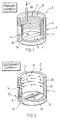
- the induction head 2 shown in Figure 1 comprises a concentrator 4 made of a material having high magnetic permeability such as aluminum, copper or silver.
- the concentrator has sidewalls 6, and endwall 8 having a measuring gap 10 formed as an interruption of the endwall 8.
- the opposite end of the concentrator is open as indicated at 12 defining a central cavity 11.
- the sidewalls are interrupted or discontinuous as indicated by the interruption 14 which is aligned with the measuring gap 10.
- the interruptions 12 and 14 cause a desired current concentration of the secondary magnetic field.
- a wound coil 18 made of insulated wire is placed inside the concentrator and is in abutment with the sidewalls 6 of the concentrator.
- the individual windings of the coil are insulated.
- An exciting current indicated by 20 which preferably is a high frequency signal is used to excite the wound coil and in so doing, produces a primary field directly associated with the wound coil 18.
- This primary field produces a secondary current, as indicated in Figure 2.
- the thickness of the sidewalls 6 of the concentrator 4 and the frequency of the exciting signal 20 produces the secondary currents 30 on the inside surface of the concentrator 4.
- These secondary currents are on the surface of the concentrator in a small skin layer of the concentrator.
- the concentrator is many times thicker than this skin layer.
- the secondary currents on the surface of the concentrator are redirected as indicated at 32 immediately adjacent the interruption 14 provided in the sidewalls 6.
- This redirection of the secondary currents causes a concentration of the secondary currents, either side of the measuring gap 10 as indicated at 34. This causes the current to cross the concentrator and then return along the opposite side of the measuring gap 10. When it reaches the far side of the measuring gap, the secondary currents are then redistributed along the inside surface of the concentrator to complete the circuit. With this arrangement, the concentrator produces a redirection of the secondary currents due to the interruption in the sidewalls and a concentration of the currents, either side of the measuring gap.
- the current has now been turned 90° and has an axis perpendicular to the axis of the primary field. The current on either side of the measuring gap has an opposite direction and thus two magnetic fields are formed at the measuring gap. As a conducting strip is passed by the measuring gap and generally aligns with the measuring gap. It first interrupts and changes the first field and then it interrupts and changes the second field. This provides an immediate transition which can easily be detected.
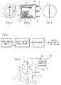
- FIGS 3, 4 and 5 show further details of the induction head 2.
- the concentrator 4 is supported by a frame 40 of an electrically insulating material. This allows the concentrator to be electrically isolated from other supporting structures.
- the wound coil 18 is still associated with the concentrator 4 and is secured by partial winding around the terminal 7 and terminal 8.
- the concentrator also has an electrical terminal 9 which is used to allow the concentrator to be used as an electrostatic screen.
- the coil 18 is an active part of the circuit for the induction head. It is made in a standard manner, preferrably with a copper insulated wire. When choosing a thickness for the wire, it is necessary to proceed from the fact that for the given overall dimensions and operational frequency of the induction head, there exists the optimal thickness of the wire. If the wire is chosen to be too thin, this reduces the induction head quality and negatively affects the possibility of registering small changes in induction. If the wire is chosen to be too thick, it can cause inefficient interaction between the coil and the concentrator or unacceptable head induction.
- the concentrator 4 is made up of material with the maximum possible specific conductance. For example, it could be made of aluminum, copper, silver, etc. Its walls are relatively thick such that the secondary currents are in a skin layer at the operational frequency. To increase the axial density of the current in the measuring gap, the height of the gap, i.e. the thickness of the bottom of the concentrator close to the gap, is reduced as much as is practical. This can be achieved by selecting the proper thickness of the bottom in the gap area. The thickness of the bottom is still much larger than the thickness of the skin layer at the operational frequency.
- the surface finish in the measuring gap is of high quality to provide the desired concentration at the measuring gap. It should be noted that the actual shape of the measuring gap and the length and width are selected based on the requirements of the parameters and the configuration of the working area of the induction head.
- the main purpose of the concentrator has already been described and it forms the configuration of the magnetic field of the induction head.
- this component also allows it to provide an electrostatic screen for the head. This is important as a high frequency signal is used in the head as part of the exciting signal. This high frequency signal ensures the required ratio between the thickness of the skin layer and the bottom of the concentrator. It also affects the sensitivity sensing of the induction head at the operational frequency.
- the capacitance of the induction head and its electronic circuitry components is small and additional, partial capacitance between the coil and a bank note moving beneath the head may change the impedance of the induction head during the measurement, which change is not due to a security thread making assessment of changes more difficult.
- the coil is powered with a considerable voltage and its capacitance coupling with other components of the device, at high frequency, may interfere with the operation of these components and cause emission into the environment, thus reducing the electromagnetic compatibility.
- FIG. 6 shows the electronic circuitry used with the induction head.
- the induction head current (?) in this circuit is converted into the frequency of the self excited oscillator, with its resonant circuits being the ones which the induction head is connected to.
- This version is of lower quality due to the transformation of the current and absence of ferromagnetic cores.
- the self-excited oscillator is sensitive to non-impedance frequency destabilizing factors.
- this very circuit requires that the coupling coefficient (k) between the head and the self-excited oscillator active components should be increased, thereby increasing the impedances of the circuit to a degree wherein active components of the circuit affect with frequency response.
- isolation measures should be axed to remove disturbances from the circuit of the self-excited oscillator circuit: for instance; stabilizing the voltage of the power supply, shielding the active components of the self-excited oscillator, etc.
- Further frequency response data processing may be conducted with the application of different standard techniques: with the digital frequency meter, the frequency modulated signal detector, etc.
- the induction head circuit operates at a relatively high operational frequency, the electric field produced at this frequency must be shielded from the working area of the induction head.
- a bank note moving through the working area has variable dielectric characteristics ( due to variations in dielectric permittivity, coefficient of dielectric losses, thickness and positioning in the pathway). These variations in the presence of an electric field in the working area, may give rise to modulations of the frequency of the oscillator (hence, bring about interferences with the sensor operation).
- the size of the width of the gap in the concentrator's bottom should be minimized.
- the employment of the concentrator as an electrostatic screen also helps to isolate the working area from external influences.
- the electrical terminal of the concentrator must be connected to a location in the circuit having a constant voltage in relation to other voltages. It is also desirable to connect the coil to the processing circuits allowing the coil end drawn nearer to the bottom of the concentrator (that is terminal 7) to have a constant potential in relation to all other potentials.
- the concentrator is made of aluminum. Its outside diameter is 8 mm, its height is 5 mm, the width of the gap is 0.4 mm, while the thickness of the sidewalls is 0.5 mm and the thickness of the bottom is 0.2 mm. To improve the resistance to wear and proper insulation, the working area of the concentrator is oxidized.
- the coil of a one-layer design and it has 20 turns of 0.15 lmm-diameter copper wire with varnished insulation.
- the coil ends are connected to the terminals pressed in the frame.
- the concentrator is connected to the terminals pressed in the frame.
- the concentrator is connected to a similar terminal.
- Another possible modification has the concentrator consisting of two halves, which means that the gap goes along both sides of the cylindrical surface.
- the direction of the Foucault currents is a bit different than that shown in Figure 2, but it also achieves the desired concentration of the magnetic field.
- the induction head is used in the oscillator designed as a Colpitts oscillator (see Figure 5).
- the induction head coil is connected to the oscillator in a manner allowing the end of the coil, closer to the bottom of the concentrator, to be connected to the common terminal of the power supply.
- Circuit 50 shows a Colpitts oscillator powered by power supply 54.
- Induction head 2 is connected to the circuit at terminals 7 and 9 to ground 62 and terminal 8 to coupling capacitor 66.
- Transistor 52 drives the circuit.
- Tuning capacitors 58 and 68 help to determine the resonant frequency of the circuit.
- the output is taken from terminal 56.
- Resistors 64 and 70 and capacitors 60 also aid in tuning the circuit.
Landscapes
- Engineering & Computer Science (AREA)
- Physics & Mathematics (AREA)
- General Physics & Mathematics (AREA)
- Life Sciences & Earth Sciences (AREA)
- Artificial Intelligence (AREA)
- Theoretical Computer Science (AREA)
- Computer Vision & Pattern Recognition (AREA)
- Remote Sensing (AREA)
- General Life Sciences & Earth Sciences (AREA)
- Geophysics (AREA)
- Electromagnetism (AREA)
- Geology (AREA)
- Environmental & Geological Engineering (AREA)
- Investigating Or Analyzing Materials By The Use Of Magnetic Means (AREA)
- Inspection Of Paper Currency And Valuable Securities (AREA)
- Measurement Of Length, Angles, Or The Like Using Electric Or Magnetic Means (AREA)
- Geophysics And Detection Of Objects (AREA)
Claims (7)
- Tête à induction pour détecter une bande magnétique ou d'autres structures de sécurité perméables de façon magnétique, ladite tête à induction (2) comprenant une bobine inductrice (18) située dans un concentrateur (4) conductible de façon électrique, ladite bobine inductrice produisant un champ primaire qui induit un courant secondaire adapté dans ledit concentrateur, ledit concentrateur comprenant des faces latérales (6) tubulaires définissant une cavité centrale creuse fermée à une extrémité par une paroi d'extrémité (8), ladite paroi d'extrémité comprenant un étroit intervalle de mesure (10) séparant ladite paroi d'extrémité en deux sections opposées, lesdites faces latérales étant également interrompues par une fente (14) adjacente à une extrémité dudit intervalle de mesure, afin de générer une concentration dudit courant secondaire pour passer le long dudit intervalle (10) qui peut être suivi pour une modification de l'induction due à la présence d'une bande magnétique allongée ou d'une autre structuré de sécurité perméable de façon magnétique déplacée au-delà de l'intervalle de mesure.
- Tête à induction selon la revendication 1, dans laquelle lesdites faces latérales sont cylindriques et comprennent une fente verticale à une extrémité dudit intervalle de mesure qui génère ladite interruption dans lesdites faces latérales.
- Tête à induction selon la revendication 2, dans laquelle ledit intervalle de mesure et ladite fente desdites faces latérales produisent une séparation à travers la plupart dudit concentrateur et génèrent une redirection et une concentration souhaitées dudit courant secondaire le long dudit intervalle de mesure.
- Tête à induction selon la revendication 2, dans laquelle ledit concentrateur est composé de matériau en aluminium.
- Tête à induction selon la revendication 4, dans laquelle ledit champ de mesure possède un axe perpendiculaire à l'axe du champ magnétique produit par ladite bobine inductrice.
- Tête à induction selon la revendication 1, dans laquelle ladite tête doit être excitée par un signal haute fréquence produisant ledit courant secondaire dans une couche de surface dudit concentrateur, en raison de l'épaisseur dudit concentrateur.
- Tête à induction selon la revendication 6, dans laquelle ledit concentrateur est composé d'aluminium, de cuivre ou d'un matériau a base d'argent.
Applications Claiming Priority (3)
| Application Number | Priority Date | Filing Date | Title |
|---|---|---|---|
| CA002230523A CA2230523C (fr) | 1998-02-25 | 1998-02-25 | Capteur inductif |
| CA2230523 | 1998-02-25 | ||
| PCT/CA1999/000065 WO1999044169A1 (fr) | 1998-02-25 | 1999-01-27 | Detecteur a induction |
Publications (2)
| Publication Number | Publication Date |
|---|---|
| EP1057136A1 EP1057136A1 (fr) | 2000-12-06 |
| EP1057136B1 true EP1057136B1 (fr) | 2003-10-01 |
Family
ID=4162156
Family Applications (1)
| Application Number | Title | Priority Date | Filing Date |
|---|---|---|---|
| EP99901553A Expired - Lifetime EP1057136B1 (fr) | 1998-02-25 | 1999-01-27 | Detecteur a induction |
Country Status (7)
| Country | Link |
|---|---|
| EP (1) | EP1057136B1 (fr) |
| JP (1) | JP2002505487A (fr) |
| CN (1) | CN1134745C (fr) |
| AU (1) | AU753651B2 (fr) |
| CA (1) | CA2230523C (fr) |
| DE (1) | DE69911745T2 (fr) |
| ES (1) | ES2209382T3 (fr) |
Families Citing this family (4)
| Publication number | Priority date | Publication date | Assignee | Title |
|---|---|---|---|---|
| JP2010257292A (ja) * | 2009-04-27 | 2010-11-11 | Hitachi Omron Terminal Solutions Corp | 媒体厚み検知装置 |
| CN101881838A (zh) * | 2010-06-23 | 2010-11-10 | 尹武良 | 一种基于电磁传感器的食品内危险物品的测量装置与方法 |
| DE102011004530A1 (de) * | 2010-12-15 | 2012-06-21 | Mahle International Gmbh | Heizvorrichtung |
| FR2979712B1 (fr) * | 2011-09-02 | 2013-09-13 | Schneider Electric Ind Sas | Ensemble multicouche a double bobinage blinde pour detecteur inductif |
Family Cites Families (2)
| Publication number | Priority date | Publication date | Assignee | Title |
|---|---|---|---|---|
| GB2173000B (en) * | 1985-03-28 | 1988-08-10 | Texaco Development Corp | Dielectric well logging system with electrostatically shielded coils |
| FR2712420B1 (fr) * | 1993-11-08 | 1995-12-15 | Commissariat Energie Atomique | Tête magnétique de lecture à élément magnétorésistant multicouche et à concentrateur et son procédé de réalisation. |
-
1998
- 1998-02-25 CA CA002230523A patent/CA2230523C/fr not_active Expired - Fee Related
-
1999
- 1999-01-27 CN CNB998033030A patent/CN1134745C/zh not_active Expired - Fee Related
- 1999-01-27 DE DE69911745T patent/DE69911745T2/de not_active Expired - Lifetime
- 1999-01-27 JP JP2000533850A patent/JP2002505487A/ja not_active Abandoned
- 1999-01-27 EP EP99901553A patent/EP1057136B1/fr not_active Expired - Lifetime
- 1999-01-27 AU AU21469/99A patent/AU753651B2/en not_active Ceased
- 1999-01-27 ES ES99901553T patent/ES2209382T3/es not_active Expired - Lifetime
Also Published As
| Publication number | Publication date |
|---|---|
| AU753651B2 (en) | 2002-10-24 |
| CA2230523A1 (fr) | 1999-08-25 |
| DE69911745T2 (de) | 2004-08-05 |
| EP1057136A1 (fr) | 2000-12-06 |
| AU2146999A (en) | 1999-09-15 |
| CA2230523C (fr) | 2006-05-09 |
| CN1134745C (zh) | 2004-01-14 |
| ES2209382T3 (es) | 2004-06-16 |
| JP2002505487A (ja) | 2002-02-19 |
| CN1292128A (zh) | 2001-04-18 |
| DE69911745D1 (de) | 2003-11-06 |
Similar Documents
| Publication | Publication Date | Title |
|---|---|---|
| KR101665145B1 (ko) | 복합 전자 측정 장치 | |
| US6462536B1 (en) | Eddy current sensor | |
| US4513257A (en) | Proximity switch with oppositely polarized coils | |
| US7336069B2 (en) | Eddy current sensor and sensor coil for the same | |
| KR20190014088A (ko) | 비접촉형 센서 | |
| JPH01206268A (ja) | 電流検出装置 | |
| JP2004518144A (ja) | 位置測定装置 | |
| EP1057136B1 (fr) | Detecteur a induction | |
| US6191575B1 (en) | Device for measuring linear displacements | |
| US6057683A (en) | Induction sensor having conductive concentrator with measuring gap | |
| JP2001165910A (ja) | 磁気センサ | |
| US3546580A (en) | Magnetic field variometer using a low noise amplifier and a coil-core arrangement of minimum weight and maximum sensitivity | |
| CA1157097A (fr) | Methode et appareil pour mesurer la capacite specifique d'un cable | |
| US3555409A (en) | Magnetic susceptibility logging system with transmitter and receiver null coils | |
| US5541503A (en) | Alternating current sensor based on concentric-pipe geometry and having a transformer for providing separate self-powering | |
| JP3203547B2 (ja) | 磁気検出素子 | |
| JP5006511B2 (ja) | 電流センサ及びそれを用いた電流検知ユニット | |
| JP4460188B2 (ja) | 磁気センサー | |
| US3355661A (en) | Apparatus for measuring the conductivity of electrolyte | |
| JPH01240867A (ja) | 電流検出器 | |
| JP5290598B2 (ja) | 核磁気共鳴装置とその信号取り出し方法 | |
| Lee | A high-bandwidth induction sensor coil | |
| JP3675780B2 (ja) | 金属疲労・劣化識別装置 | |
| GB1388875A (en) | Magnetic field sensing apparatus | |
| JPH04216401A (ja) | 渦電流測定法による変位トランスデューサ測定シーケンスを平衡させるための方法および装置 |
Legal Events
| Date | Code | Title | Description |
|---|---|---|---|
| PUAI | Public reference made under article 153(3) epc to a published international application that has entered the european phase |
Free format text: ORIGINAL CODE: 0009012 |
|
| 17P | Request for examination filed |
Effective date: 20000731 |
|
| AK | Designated contracting states |
Kind code of ref document: A1 Designated state(s): DE ES GB |
|
| GRAG | Despatch of communication of intention to grant |
Free format text: ORIGINAL CODE: EPIDOS AGRA |
|
| 17Q | First examination report despatched |
Effective date: 20020626 |
|
| GRAG | Despatch of communication of intention to grant |
Free format text: ORIGINAL CODE: EPIDOS AGRA |
|
| GRAH | Despatch of communication of intention to grant a patent |
Free format text: ORIGINAL CODE: EPIDOS IGRA |
|
| GRAH | Despatch of communication of intention to grant a patent |
Free format text: ORIGINAL CODE: EPIDOS IGRA |
|
| GRAA | (expected) grant |
Free format text: ORIGINAL CODE: 0009210 |
|
| AK | Designated contracting states |
Kind code of ref document: B1 Designated state(s): DE ES GB |
|
| REG | Reference to a national code |
Ref country code: GB Ref legal event code: FG4D |
|
| REF | Corresponds to: |
Ref document number: 69911745 Country of ref document: DE Date of ref document: 20031106 Kind code of ref document: P |
|
| REG | Reference to a national code |
Ref country code: ES Ref legal event code: FG2A Ref document number: 2209382 Country of ref document: ES Kind code of ref document: T3 |
|
| PLBE | No opposition filed within time limit |
Free format text: ORIGINAL CODE: 0009261 |
|
| STAA | Information on the status of an ep patent application or granted ep patent |
Free format text: STATUS: NO OPPOSITION FILED WITHIN TIME LIMIT |
|
| 26N | No opposition filed |
Effective date: 20040702 |
|
| REG | Reference to a national code |
Ref country code: ES Ref legal event code: PC2A Owner name: CRANE CANADA CO. Effective date: 20150130 |
|
| REG | Reference to a national code |
Ref country code: GB Ref legal event code: 732E Free format text: REGISTERED BETWEEN 20150129 AND 20150204 |
|
| REG | Reference to a national code |
Ref country code: DE Ref legal event code: R082 Ref document number: 69911745 Country of ref document: DE Representative=s name: BUSCHHOFF-HENNICKE-ALTHAUS, DE |
|
| REG | Reference to a national code |
Ref country code: DE Ref legal event code: R082 Ref document number: 69911745 Country of ref document: DE Representative=s name: BUSCHHOFF-HENNICKE-ALTHAUS, DE Effective date: 20150512 Ref country code: DE Ref legal event code: R081 Ref document number: 69911745 Country of ref document: DE Owner name: CRANE CANADA CO., TORONTO, CA Free format text: FORMER OWNER: CASHCODE COMPANY INC., CONCORD, ONTARIO, CA Effective date: 20150512 |
|
| REG | Reference to a national code |
Ref country code: DE Ref legal event code: R082 Ref document number: 69911745 Country of ref document: DE |
|
| PGFP | Annual fee paid to national office [announced via postgrant information from national office to epo] |
Ref country code: GB Payment date: 20180125 Year of fee payment: 20 Ref country code: DE Payment date: 20180109 Year of fee payment: 20 Ref country code: ES Payment date: 20180213 Year of fee payment: 20 |
|
| REG | Reference to a national code |
Ref country code: DE Ref legal event code: R071 Ref document number: 69911745 Country of ref document: DE |
|
| REG | Reference to a national code |
Ref country code: GB Ref legal event code: PE20 Expiry date: 20190126 |
|
| PG25 | Lapsed in a contracting state [announced via postgrant information from national office to epo] |
Ref country code: GB Free format text: LAPSE BECAUSE OF EXPIRATION OF PROTECTION Effective date: 20190126 |
|
| REG | Reference to a national code |
Ref country code: ES Ref legal event code: FD2A Effective date: 20220128 |
|
| PG25 | Lapsed in a contracting state [announced via postgrant information from national office to epo] |
Ref country code: ES Free format text: LAPSE BECAUSE OF EXPIRATION OF PROTECTION Effective date: 20190128 |