EP1056975B1 - Wärmetauscheranordnung - Google Patents
Wärmetauscheranordnung Download PDFInfo
- Publication number
- EP1056975B1 EP1056975B1 EP99906210A EP99906210A EP1056975B1 EP 1056975 B1 EP1056975 B1 EP 1056975B1 EP 99906210 A EP99906210 A EP 99906210A EP 99906210 A EP99906210 A EP 99906210A EP 1056975 B1 EP1056975 B1 EP 1056975B1
- Authority
- EP
- European Patent Office
- Prior art keywords
- heat exchanger
- heating
- ndv
- condensate
- chamber
- Prior art date
- Legal status (The legal status is an assumption and is not a legal conclusion. Google has not performed a legal analysis and makes no representation as to the accuracy of the status listed.)
- Expired - Lifetime
Links
Images

Classifications
-
- F—MECHANICAL ENGINEERING; LIGHTING; HEATING; WEAPONS; BLASTING
- F22—STEAM GENERATION
- F22D—PREHEATING, OR ACCUMULATING PREHEATED, FEED-WATER FOR STEAM GENERATION; FEED-WATER SUPPLY FOR STEAM GENERATION; CONTROLLING WATER LEVEL FOR STEAM GENERATION; AUXILIARY DEVICES FOR PROMOTING WATER CIRCULATION WITHIN STEAM BOILERS
- F22D1/00—Feed-water heaters, i.e. economisers or like preheaters
- F22D1/32—Feed-water heaters, i.e. economisers or like preheaters arranged to be heated by steam, e.g. bled from turbines
Definitions
- the invention relates to a heat exchanger arrangement for fluid heating, in particular for water heating a housing in which at least two heating chambers for the fluid to be heated are arranged in series, one heat exchanger in each of the heating chambers, a common intermediate chamber, in which the outlet of the first heat exchanger and the inlet of the downstream second heat exchanger open, and a wall which separates the two heating chambers from one another and is built into the housing and has a cutout which is adapted to the circumference of the intermediate chamber and is connected in a gas-tight manner on its circumference to an inner wall of the housing and in a gas-tight manner on its cutting edge to the circumference of the intermediate chamber.
- Such a heat exchanger arrangement is from DE 195 37 478 C1 known.
- the two heat exchangers are as Tube heat exchanger trained.
- the two heating chambers a common busbar is assigned, via which the condensed bleed steam from the on different Pressure level located heating chambers is derived.
- the Partition therefore only causes partial decoupling of the two pressure ranges.
- the invention has for its object a particular to create compact heat exchanger arrangement, namely under simultaneous improvement in efficiency.
- the heat exchanger arrangement mentioned at the outset is characterized according to the invention in that that the heat exchanger is designed as a welded plate heat exchanger and that the partition (17) with the intermediate chamber (13) and the housing inner wall is gas-tight, in particular welded, and that the first heating chamber has a condensate drain which is connected to the intermediate chamber via a condensate siphon, the condensate in the intermediate chamber being mixed with fluid emerging from the first plate heat exchanger and being heated in the second plate heat exchanger.
- the well-known welded plate heat exchangers are therefore in a space-saving way arranged in a common housing.
- the heating chambers gastight, i.e. separated from each other in a pressure-tight manner, so that there is no loss of efficiency in this regard can.
- the condensate lifter conveys the heating condensate out of the heating chamber operating at a lower pressure level in the Intermediate chamber, so that it is subsequently in the downstream Reheated heating chamber and therefore optimal in terms of exergy is being used.
- Welded plate heat exchangers especially hybrid heat exchangers with undulated passage channels for the fluid to be heated and with transverse channels for the Heating fluids are more comparable to tubular heat exchangers Performance much more compact and cheaper manufacture.
- the inventive integration of the outlet chamber of the first plate heat exchanger with the inlet chamber of the second plate heat exchanger minimizes the Size and the cost of the entire heat exchanger arrangement.
- the housing has a cylindrical Has jacket and the heat exchanger and the intermediate chamber are aligned on the cylinder axis.
- the intermediate chamber is preferably box-shaped and has a substantially rectangular cross section.
- the Partition has a rectangular cross-sectional profile Intermediate chamber adapted cutout and a circular Scope.
- the performance of the flow of the fluid to be heated first plate heat exchanger is larger, preferably 100 to 300% larger than the performance of the downstream plate heat exchanger.
- the length dimensions of the second are also corresponding Plate heat exchanger correspondingly lower than those of the first plate heat exchanger.
- the aspect ratio is in the range of 1/2 to 3/4.
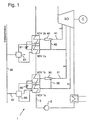
- Figure 1 is a low pressure preheating line 1 with a first double chamber low pressure preheater NDV 1a and NDV 1b and a second double chamber low pressure preheater NDV 2a and NDV 2b.
- the preheaters NDV 1a and NDV 2a are with steam from taps A1 and A2 from a low-pressure turbine ND powered.
- the main condensate is from a pump 2 conveyed via the main condensate line 3 and in the LP preheating line 1 preheated in several stages.
- the bleed steam A1 is from the Propellant steam from A2 is sucked in and flows through the exchange of impulses after increasing the pressure in the steam jet 30 into the NDV 1b.
- the downstream preheating stages NDV 2a and NDV 2b are similar to the first stages NDV 1a and NDV 1b, where the heating NDV 2a from A2 with heating steam and the stage NDV 2b is fed from the steam jet 40.
- Via a suction line 42 the bleed steam A2 from Driving steam from A3 sucked in by pulse exchange.
- the preheating arrangement corresponds to that according to DE-PS 195 41 543.
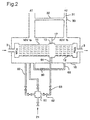
- the essential new aspect of the invention lies in the formation of the heat exchanger arrangement in each of the low pressure double chamber preheaters NDV 1a / 1b. For this purpose, reference is made to FIG. 2 of the drawing.
- the double chamber preheater is in the embodiment 2 from two welded plate heat exchangers 11, 12, which are connected to one another via an intermediate chamber 13 are connected.
- the main condensate emerges from the main condensate line 3 in the direction of the arrow into a water chamber WKa on the inlet side and is in the first heating chamber, which is the first preheating stage NDV 1a, preheated with tap steam A1.
- the exhaust side Water chamber of the first plate heat exchanger 11 and the inlet-side water chamber of the outlet-side plate heat exchanger 12 are in the intermediate chamber 13 to one Unit summarized. Passes through the intermediate chamber 13 the main condensate in the second plate heat exchanger 12.
- Another main condensate preheat is carried out here a steam mixture from the steam jet 30.
- Das Main condensate warmed up in two stages leaves the double chamber preheater via an outlet-side water chamber WKb.
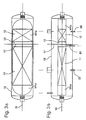
- the heat exchanger combination 11, 13 and 12 is like that Figures 3a and b show particularly clearly in a cylindrical Housing installed, the heat exchanger 11th and 12 and the intermediate chamber 13 on the cylinder axis 16 are aligned.
- the intermediate chamber 13 is box-shaped trained and has a rectangular cross section (figures 3a and 3b).
- the two heating chambers of the preheating stages NDV 1a and NDV 1b are by means of a flat partition 17 separated from each other in a pressure-tight manner.
- the partition is along its peripheral edge welded to the housing jacket and has an axial cutout that matches the rectangular perimeter adapted to the intermediate chamber 13 and welded to it is.
- the new heat exchanger arrangement is also characterized by a particularly compact design, which makes it space-saving Installation becomes possible.
- the plate heat exchanger used in the described Execution example of a so-called hybrid heat exchanger. Whose Training is shown schematically in Figure 4.
- the main condensate flow flows through the plate exchanger module via undulated channels. Between the condensate flow channels are intersecting heating steam ducts in the manner of tubes with diamond-shaped cross sections arranged.
- the heating steam condensate of the first preheating stage NDV 1a is a condensate drain 52, a shut-off valve and a check valve is directed into the condensate lifter 50.
- a float is attached to a condensate lifter Lever arrangement a motive steam inlet valve and a steam outlet valve controls in opposite directions.
- the last two Valves are integrated in the condensate lifter.
- the heating condensate is in the intermediate chamber 13 mixed with the main condensate and in the following Heat exchanger stage 12 of the second heating chamber heated.
- the motive steam is released from the condensate siphon relieved in the heating chamber NDV 1a and is used there to preheat the condensate.
- the heating condensate from the second heating chamber NDV 1b is via a condensate drain 66 and an adjustable Throttle 60 cascaded into the first heating chamber NDV 1a.
- This circuit arrangement is particularly inexpensive; because an adjustable throttle is much cheaper than one Pump Trap.
- a ratio of approximately 4: 3 to 2: 1 has proven to be favorable for the preferred application for preheating of the main condensate in power plant processes.
- the second double chamber preheater arrangement is NDV 2a / 2b the first preheating arrangement NDV 1a / 1b and has otherwise the training described with reference to Figure 2 and arrangement. To avoid repetitions, this is done Referred.
Landscapes
- Engineering & Computer Science (AREA)
- Physics & Mathematics (AREA)
- Thermal Sciences (AREA)
- Mechanical Engineering (AREA)
- General Engineering & Computer Science (AREA)
- Heat-Exchange Devices With Radiators And Conduit Assemblies (AREA)
- Separation By Low-Temperature Treatments (AREA)
- Compression-Type Refrigeration Machines With Reversible Cycles (AREA)
- Lining Or Joining Of Plastics Or The Like (AREA)
Description
einem Gehäuse, in welchem mindestens zwei Aufheizkammern für das aufzuheizende Fluid seriell angeordnet sind,
je einem Wärmetauscher in jeder der Aufheizkammern,
einer gemeinsamen Zwischenkammer, in der der Ausgang des ersten Wärmetauschers und der Eingang des nachgeschalteten zweiten Wärmetauschers münden, und
einer die beiden Aufheizkammern voneinander trennenden, in das Gehäuse eingebauten Wand, die einen dem Umfang der Zwischenkammer angepaßten Ausschnitt hat und an ihrem Umfang gasdicht mit einer Gehäuseinnenwand und an ihrem Ausschnittrand gasdicht mit dem Umfang der Zwischenkammer verbunden ist.
daß die Wärmetauscher als geschweißte Plattenwärmetauscher ausgebildet sind und daß die Trennwand (17) mit der Zwischenkammer (13) und der Gehäuseinnenwand gasdicht verbunden, insbesondere verschweißt ist, und
daß die erste Aufheizkammer einen Kondensatablauf hat, der über einen Kondensatheber mit der Zwischenkammer verbunden ist, wobei das Kondensat in der Zwischenkammer mit aus dem ersten Plattenwärmetauscher austretendem Fluid gemischt und in dem zweiten Plattenwärmetauscher aufgeheizt wird.
- Figur 1
- eine Übersichtsschaltung einer Niederdruck-Vorwärmstraße mit zwei Doppelkammer-Warmetauschern gemäß einem Ausführungsbeispiel der Erfindung sowie deren Einbindung in den Kraftwerksprozeß;
- Figur 2
- ein Ausführungsbeispiel einer der beiden Wärmetauscheranordnungen gemäß Figur 1 mit den wesentlichen Komponenten und Anschlüssen;
- Figur 3a und 3b
- schematische axiale Ansichten durch ein Ausführungsbeispiel der neuen Wärmetauscheranordnung; und
- Figur 4
- einen Teilschnitt durch ein Ausführungsbeispiel eines Hybridwärmetauschers.
Claims (10)
- Wärmetauscheranordnung zur Fluidaufheizung, insbesondere zur Wasseraufheizung, mit
einem Gehäuse (15), in welchem mindestens zwei Aufheizkammern (NDV 1a/1b) für das aufzuheizende Fluid seriell angeordnet sind,
je einem Wärmetauscher (11, 12) in jeder der Aufheizkammern,
einer gemeinsamen Zwischenkammer (13), in der der Ausgang des ersten Wärmetauschers (11) und der Eingang des nachgeschalteten zweiten Wärmetauschers (12) münden, und
einer die beiden Aufheizkammern voneinander trennenden, in das Gehäuse (15) eingebauten Wand (17), die einen dem Umfang der Zwischenkammer (13) angepaßten Ausschnitt hat und an ihrem Umfang gasdicht mit einer Gehäuseinnenwand und an ihrem Ausschnittrand gasdicht mit dem Umfang der Zwischenkammer verbunden ist,
dadurch gekennzeichnet, daß die Wärmetauscher als geschweißte Plattenwärmetauscher (11, 12) ausgebildet sind und daß die Trennwand (17) mit der Zwischenkammer (13) und der Gehäuseinnenwand gasdicht verbunden, insbesondere verschweißt ist, und
daß die erste Aufheizkammer (NDV 1a) einen Kondensatablauf (52) hat, der über einen Kondensatheber (50) mit der Zwischenkammer (13) verbunden ist, wobei das Kondensat in der Zwischenkammer mit aus dem ersten Plattenwärmetauscher (11) austretendem Fluid gemischt und in dem zweiten Plattenwärmetauscher (12) aufgeheizt wird. - Wärmetauscheranordnung nach Anspruch 1, dadurch gekennzeichnet, daß das Gehäuse (15) einen zylindrischen Mantel hat und die Wärmetauscher (11, 12) und die Zwischenkammer (13) auf der Zylinderachse (16) ausgerichtet sind.
- Wärmetauscheranordnung nach Anspruch 2, dadurch gekennzeichnet, daß die Zwischenkammer (15) kastenförmig ausgebildet ist und einen im wesentlichen rechteckigen Querschnitt hat und daß die Trennwand (17) einen dem rechteckigen Querschnittsprofil angepaßten Ausschnitt und einen kreisförmigen Umfang hat.
- Wärmetauscheranordnung nach einem der Ansprüche 1 bis 3, dadurch gekennzeichnet, daß in jeder Aufheizkammer (NDV 1a/1b) ein Hybridwärmetauscher mit ondulierten Durchtrittskanälen für das aufzuheizende Fluid und mit querverlaufenden Kanälen für das Heizfluid angeordnet ist.
- Wärmetauscheranordnung nach einem der Ansprüche 1 bis 4, dadurch gekennzeichnet, daß die Leistung des in Strömungsrichtung des aufzuheizenden Fluids ersten Plattenwärmetauschers (11) größer, vorzugweise um 100 bis 300% größer ist als die Leistung des nachgeschalteten Plattenwärmetauschers (12).
- Wärmetauscheranordnung nach Anspruch 5, dadurch gekennzeichnet, daß das Längenverhältnis des ersten Plattenwärmetauschers (11) zum zweiten Plattenwärmetauscher (12) im Bereich von 2 bis 1,5.
- Wärmetauscheranordnung nach einem der Ansprüche 1 bis 6, dadurch gekennzeichnet, daß ein Kondensatablauf (66) der zweiten Aufheizkammer (NDV 1b) über eine einstellbare Drossel (60) mit der ersten Aufheizkammer (NDV 1a) verbunden ist.
- Wärmetauscheranordnung nach einem der Ansprüche 1 bis 7, dadurch gekennzeichnet, daß die Wärmetauscheranordnung zum Vorwärmen des Hauptkondensats in einem Kraftwerksprozeß dient, wobei die erste Aufheizkammer (NDV 1a) mit einer Anzapfung (A1) einer Turbine (ND) und die zweite Aufheizkammer (NDV 1b) mit einem Dampfstrahler (30) verbunden ist, dessen Treibdampfanschluß (31) aus einer zweiten Turbinenanzapfung (A2) gespeist wird.
- Wärmetauscheranordnung nach Anspruch 8, dadurch gekennzeichnet, daß der Ansauganschluß (32) des Dampfstrahlers (30) und die erste Aufheizkammer (NDV 1a) aus der gleichen Dampfquelle (A1) gespeist sind.
- Wärmetauscheranordnung nach Anspruch 9, dadurch gekennzeichnet, daß der Mischdampf am Ausgang des Dampfstrahlers einen Druck hat, der um einen Faktor von 1,3 bis 1,5 höher ist als der Druck des Saugdampfes.
Applications Claiming Priority (3)
| Application Number | Priority Date | Filing Date | Title |
|---|---|---|---|
| DE19806238A DE19806238C1 (de) | 1998-02-16 | 1998-02-16 | Wärmetauscheranordnung |
| DE19806238 | 1998-02-16 | ||
| PCT/EP1999/000541 WO1999041547A1 (de) | 1998-02-16 | 1999-01-28 | Wärmetauscheranordnung |
Publications (2)
| Publication Number | Publication Date |
|---|---|
| EP1056975A1 EP1056975A1 (de) | 2000-12-06 |
| EP1056975B1 true EP1056975B1 (de) | 2002-04-24 |
Family
ID=7857828
Family Applications (1)
| Application Number | Title | Priority Date | Filing Date |
|---|---|---|---|
| EP99906210A Expired - Lifetime EP1056975B1 (de) | 1998-02-16 | 1999-01-28 | Wärmetauscheranordnung |
Country Status (6)
| Country | Link |
|---|---|
| EP (1) | EP1056975B1 (de) |
| AT (1) | ATE216765T1 (de) |
| DE (2) | DE19806238C1 (de) |
| PL (1) | PL342214A1 (de) |
| TR (1) | TR200002365T2 (de) |
| WO (1) | WO1999041547A1 (de) |
Family Cites Families (3)
| Publication number | Priority date | Publication date | Assignee | Title |
|---|---|---|---|---|
| DE19535318C2 (de) * | 1995-09-22 | 1997-11-27 | Steag Ag | Verfahren und Anordnung zum Vorwärmen des Speisewassers eines Dampferzeugers in Kraftwerksprozessen |
| DE19537478C1 (de) * | 1995-10-09 | 1996-12-12 | Siemens Ag | Dampfturbinenanlage |
| DE19541543C2 (de) * | 1995-11-08 | 1997-10-16 | Steag Ag | Verfahren und Anordnung zum Vorwärmen des Hauptkondensats in Kraftwerksprozessen |
-
1998
- 1998-02-16 DE DE19806238A patent/DE19806238C1/de not_active Expired - Fee Related
-
1999
- 1999-01-28 PL PL99342214A patent/PL342214A1/xx unknown
- 1999-01-28 DE DE59901298T patent/DE59901298D1/de not_active Expired - Lifetime
- 1999-01-28 TR TR2000/02365T patent/TR200002365T2/xx unknown
- 1999-01-28 EP EP99906210A patent/EP1056975B1/de not_active Expired - Lifetime
- 1999-01-28 AT AT99906210T patent/ATE216765T1/de active
- 1999-01-28 WO PCT/EP1999/000541 patent/WO1999041547A1/de not_active Ceased
Also Published As
| Publication number | Publication date |
|---|---|
| EP1056975A1 (de) | 2000-12-06 |
| PL342214A1 (en) | 2001-05-21 |
| TR200002365T2 (tr) | 2000-12-21 |
| ATE216765T1 (de) | 2002-05-15 |
| WO1999041547A1 (de) | 1999-08-19 |
| DE19806238C1 (de) | 1999-04-15 |
| DE59901298D1 (de) | 2002-05-29 |
Similar Documents
| Publication | Publication Date | Title |
|---|---|---|
| EP1305561B1 (de) | Vorrichtung zur wärmeübertragung | |
| DE10349150A1 (de) | Wärmeübertrager, insbesondere für Kraftfahrzeuge | |
| DE4006982C2 (de) | Gasturbinentriebwerk | |
| WO1999010628A1 (de) | Dampferzeuger, insbesondere abhitzedampferzeuger, und verfahren zum betrieb dieses dampferzeugers | |
| DE10303595A1 (de) | Mehrkanal-Wärmeübertrager- und Anschlusseinheit | |
| DE2900014A1 (de) | Gasturbinenvorrichtung | |
| EP2839135A1 (de) | Mikro-gasturbinenanlage mit einem rohrförmigen rekuperator | |
| EP1104838A2 (de) | Kombikraftwerk | |
| WO1999057421A1 (de) | Gas- und dampfturbinenanlage | |
| CH645433A5 (de) | Kombinierte gasturbinen-dampfkraftanlage. | |
| EP3482080A1 (de) | Getriebeturbomaschine | |
| DE10303341A1 (de) | Luftkühler für Kraftwerksanlagen sowie Anwendung eines solchen Luftkühlers | |
| DE2922832A1 (de) | Kondensationseinheit fuer eine waermepumpe | |
| DE102008062455A1 (de) | Schaltbare Solarheizeinrichtung für eine Gasturbine | |
| EP1995416A1 (de) | Dampfturbinenanlage, kombiniertes Gas- und Dampfturbinenkraftwerk sowie Dampfkraftwerk | |
| DE19806238C1 (de) | Wärmetauscheranordnung | |
| EP2199692A2 (de) | Kompakt-Heizzentrale | |
| WO2019241898A1 (de) | Gasturbine und ein verfahren zum betreiben einer gasturbine | |
| EP4445026A1 (de) | Wasserstoff-verdichter | |
| DE3151414A1 (de) | "radialturbine" | |
| DE2808952C3 (de) | Sockel für einen Turbokompressor | |
| DE10004187C1 (de) | Verfahren zum Betreiben einer Gas- und Dampfturbinenanlage sowie danach arbeitende Anlage | |
| DE2553397C2 (de) | Röhrenwärmetauscher mit gewickeltem Rohrbündel | |
| EP0773348B1 (de) | Verfahren und Anordnung zum Vorwärmen des Hauptkondensats in Kraftwerksprozessen | |
| DE10341644B4 (de) | Wendelförmiger Wärmeaustauscher |
Legal Events
| Date | Code | Title | Description |
|---|---|---|---|
| PUAI | Public reference made under article 153(3) epc to a published international application that has entered the european phase |
Free format text: ORIGINAL CODE: 0009012 |
|
| 17P | Request for examination filed |
Effective date: 20000912 |
|
| AK | Designated contracting states |
Kind code of ref document: A1 Designated state(s): AT BE CH DE DK ES FI FR GB GR IE IT LI LU NL PT SE |
|
| GRAG | Despatch of communication of intention to grant |
Free format text: ORIGINAL CODE: EPIDOS AGRA |
|
| 17Q | First examination report despatched |
Effective date: 20010710 |
|
| GRAG | Despatch of communication of intention to grant |
Free format text: ORIGINAL CODE: EPIDOS AGRA |
|
| GRAH | Despatch of communication of intention to grant a patent |
Free format text: ORIGINAL CODE: EPIDOS IGRA |
|
| GRAH | Despatch of communication of intention to grant a patent |
Free format text: ORIGINAL CODE: EPIDOS IGRA |
|
| REG | Reference to a national code |
Ref country code: GB Ref legal event code: IF02 |
|
| GRAA | (expected) grant |
Free format text: ORIGINAL CODE: 0009210 |
|
| AK | Designated contracting states |
Kind code of ref document: B1 Designated state(s): AT BE CH DE DK ES FI FR GB GR IE IT LI LU NL PT SE |
|
| PG25 | Lapsed in a contracting state [announced via postgrant information from national office to epo] |
Ref country code: NL Free format text: LAPSE BECAUSE OF FAILURE TO SUBMIT A TRANSLATION OF THE DESCRIPTION OR TO PAY THE FEE WITHIN THE PRESCRIBED TIME-LIMIT Effective date: 20020424 Ref country code: IT Free format text: LAPSE BECAUSE OF FAILURE TO SUBMIT A TRANSLATION OF THE DESCRIPTION OR TO PAY THE FEE WITHIN THE PRE;WARNING: LAPSES OF ITALIAN PATENTS WITH EFFECTIVE DATE BEFORE 2007 MAY HAVE OCCURRED AT ANY TIME BEFORE 2007. THE CORRECT EFFECTIVE DATE MAY BE DIFFERENT FROM THE ONE RECORDED.SCRIBED TIME-LIMIT Effective date: 20020424 Ref country code: IE Free format text: LAPSE BECAUSE OF FAILURE TO SUBMIT A TRANSLATION OF THE DESCRIPTION OR TO PAY THE FEE WITHIN THE PRESCRIBED TIME-LIMIT Effective date: 20020424 Ref country code: GR Free format text: LAPSE BECAUSE OF FAILURE TO SUBMIT A TRANSLATION OF THE DESCRIPTION OR TO PAY THE FEE WITHIN THE PRESCRIBED TIME-LIMIT Effective date: 20020424 Ref country code: FR Free format text: LAPSE BECAUSE OF FAILURE TO SUBMIT A TRANSLATION OF THE DESCRIPTION OR TO PAY THE FEE WITHIN THE PRESCRIBED TIME-LIMIT Effective date: 20020424 Ref country code: FI Free format text: LAPSE BECAUSE OF FAILURE TO SUBMIT A TRANSLATION OF THE DESCRIPTION OR TO PAY THE FEE WITHIN THE PRESCRIBED TIME-LIMIT Effective date: 20020424 |
|
| REF | Corresponds to: |
Ref document number: 216765 Country of ref document: AT Date of ref document: 20020515 Kind code of ref document: T |
|
| REG | Reference to a national code |
Ref country code: GB Ref legal event code: FG4D Free format text: NOT ENGLISH |
|
| REG | Reference to a national code |
Ref country code: CH Ref legal event code: EP |
|
| REF | Corresponds to: |
Ref document number: 59901298 Country of ref document: DE Date of ref document: 20020529 |
|
| REG | Reference to a national code |
Ref country code: IE Ref legal event code: FG4D Free format text: GERMAN |
|
| PG25 | Lapsed in a contracting state [announced via postgrant information from national office to epo] |
Ref country code: SE Free format text: LAPSE BECAUSE OF FAILURE TO SUBMIT A TRANSLATION OF THE DESCRIPTION OR TO PAY THE FEE WITHIN THE PRESCRIBED TIME-LIMIT Effective date: 20020724 Ref country code: PT Free format text: LAPSE BECAUSE OF FAILURE TO SUBMIT A TRANSLATION OF THE DESCRIPTION OR TO PAY THE FEE WITHIN THE PRESCRIBED TIME-LIMIT Effective date: 20020724 Ref country code: DK Free format text: LAPSE BECAUSE OF FAILURE TO SUBMIT A TRANSLATION OF THE DESCRIPTION OR TO PAY THE FEE WITHIN THE PRESCRIBED TIME-LIMIT Effective date: 20020724 |
|
| GBT | Gb: translation of ep patent filed (gb section 77(6)(a)/1977) |
Effective date: 20020719 |
|
| NLV1 | Nl: lapsed or annulled due to failure to fulfill the requirements of art. 29p and 29m of the patents act | ||
| PG25 | Lapsed in a contracting state [announced via postgrant information from national office to epo] |
Ref country code: ES Free format text: LAPSE BECAUSE OF FAILURE TO SUBMIT A TRANSLATION OF THE DESCRIPTION OR TO PAY THE FEE WITHIN THE PRESCRIBED TIME-LIMIT Effective date: 20021030 |
|
| REG | Reference to a national code |
Ref country code: IE Ref legal event code: FD4D Ref document number: 1056975E Country of ref document: IE |
|
| EN | Fr: translation not filed | ||
| PG25 | Lapsed in a contracting state [announced via postgrant information from national office to epo] |
Ref country code: LU Free format text: LAPSE BECAUSE OF NON-PAYMENT OF DUE FEES Effective date: 20030128 |
|
| PG25 | Lapsed in a contracting state [announced via postgrant information from national office to epo] |
Ref country code: LI Free format text: LAPSE BECAUSE OF NON-PAYMENT OF DUE FEES Effective date: 20030131 Ref country code: CH Free format text: LAPSE BECAUSE OF NON-PAYMENT OF DUE FEES Effective date: 20030131 Ref country code: BE Free format text: LAPSE BECAUSE OF NON-PAYMENT OF DUE FEES Effective date: 20030131 |
|
| PLBE | No opposition filed within time limit |
Free format text: ORIGINAL CODE: 0009261 |
|
| STAA | Information on the status of an ep patent application or granted ep patent |
Free format text: STATUS: NO OPPOSITION FILED WITHIN TIME LIMIT |
|
| 26N | No opposition filed |
Effective date: 20030127 |
|
| REG | Reference to a national code |
Ref country code: CH Ref legal event code: PL |
|
| PGFP | Annual fee paid to national office [announced via postgrant information from national office to epo] |
Ref country code: DE Payment date: 20110121 Year of fee payment: 13 Ref country code: AT Payment date: 20110113 Year of fee payment: 13 |
|
| PGFP | Annual fee paid to national office [announced via postgrant information from national office to epo] |
Ref country code: GB Payment date: 20110120 Year of fee payment: 13 |
|
| REG | Reference to a national code |
Ref country code: DE Ref legal event code: R081 Ref document number: 59901298 Country of ref document: DE Owner name: STEAG ENERGY SERVICES GMBH, DE Free format text: FORMER OWNER: EVONIK ENERGY SERVICES GMBH, 45128 ESSEN, DE Effective date: 20120217 |
|
| REG | Reference to a national code |
Ref country code: AT Ref legal event code: HC Ref document number: 216765 Country of ref document: AT Kind code of ref document: T Owner name: STEAG ENERGY SERVICES GMBH, DE Effective date: 20120427 |
|
| GBPC | Gb: european patent ceased through non-payment of renewal fee |
Effective date: 20120128 |
|
| PG25 | Lapsed in a contracting state [announced via postgrant information from national office to epo] |
Ref country code: GB Free format text: LAPSE BECAUSE OF NON-PAYMENT OF DUE FEES Effective date: 20120128 Ref country code: DE Free format text: LAPSE BECAUSE OF NON-PAYMENT OF DUE FEES Effective date: 20120801 |
|
| REG | Reference to a national code |
Ref country code: DE Ref legal event code: R119 Ref document number: 59901298 Country of ref document: DE Effective date: 20120801 |
|
| REG | Reference to a national code |
Ref country code: AT Ref legal event code: MM01 Ref document number: 216765 Country of ref document: AT Kind code of ref document: T Effective date: 20120128 |
|
| PG25 | Lapsed in a contracting state [announced via postgrant information from national office to epo] |
Ref country code: AT Free format text: LAPSE BECAUSE OF NON-PAYMENT OF DUE FEES Effective date: 20120128 |