EP1056227B1 - Multi-point optical link in a cellular radio system for CDMA signals - Google Patents
Multi-point optical link in a cellular radio system for CDMA signals Download PDFInfo
- Publication number
- EP1056227B1 EP1056227B1 EP99109293A EP99109293A EP1056227B1 EP 1056227 B1 EP1056227 B1 EP 1056227B1 EP 99109293 A EP99109293 A EP 99109293A EP 99109293 A EP99109293 A EP 99109293A EP 1056227 B1 EP1056227 B1 EP 1056227B1
- Authority
- EP
- European Patent Office
- Prior art keywords
- signal
- downlink
- optical
- frequency
- electrical
- Prior art date
- Legal status (The legal status is an assumption and is not a legal conclusion. Google has not performed a legal analysis and makes no representation as to the accuracy of the status listed.)
- Expired - Lifetime
Links
Images



Classifications
-
- H—ELECTRICITY
- H04—ELECTRIC COMMUNICATION TECHNIQUE
- H04B—TRANSMISSION
- H04B10/00—Transmission systems employing electromagnetic waves other than radio-waves, e.g. infrared, visible or ultraviolet light, or employing corpuscular radiation, e.g. quantum communication
- H04B10/25—Arrangements specific to fibre transmission
- H04B10/2575—Radio-over-fibre, e.g. radio frequency signal modulated onto an optical carrier
- H04B10/25752—Optical arrangements for wireless networks
- H04B10/25753—Distribution optical network, e.g. between a base station and a plurality of remote units
-
- H—ELECTRICITY
- H04—ELECTRIC COMMUNICATION TECHNIQUE
- H04B—TRANSMISSION
- H04B10/00—Transmission systems employing electromagnetic waves other than radio-waves, e.g. infrared, visible or ultraviolet light, or employing corpuscular radiation, e.g. quantum communication
- H04B10/25—Arrangements specific to fibre transmission
- H04B10/2575—Radio-over-fibre, e.g. radio frequency signal modulated onto an optical carrier
- H04B10/25752—Optical arrangements for wireless networks
-
- H—ELECTRICITY
- H04—ELECTRIC COMMUNICATION TECHNIQUE
- H04J—MULTIPLEX COMMUNICATION
- H04J14/00—Optical multiplex systems
- H04J14/02—Wavelength-division multiplex systems
- H04J14/0298—Wavelength-division multiplex systems with sub-carrier multiplexing [SCM]
Definitions
- the present invention relates to an optical transmission system of claim 3, to a multi-point optical transmission method according to the generic part of claim 1 and for a master station according to the generic part of claim 2.
- Fig. 4 is a block diagram showing an exemplary functional configuration of a conventional multi-point optical transmission system.
- the system in Fig. 4 includes radio base stations 40 1 to 40 n (where n is an arbitrary integer of 2 or more) and a switching station 41, and each of the radio base stations 40 1 to 40 n is connected to the switching station 41 via an optical fiber 43.
- Each radio base station 40 1 to 40 n includes an antenna 401, a driving section 402, and an uplink electrical-optical converting section 403.
- the switching station 41 includes uplink optical-electrical converting sections 411 1 to 411 n , demodulating sections 412 1 to 412 n , and a switching section 413.
- the antenna 401 receives an uplink radio signal.
- the uplink radio signal herein is a code-division multiplex signal into which radio signals outputted from a plurality of terminals (not shown) in each cell 42 are multiplexed in a code-division system. Each uplink radio signal is equal in frequency as predetermined.
- the driving section 402 applies a bias to the uplink radio signal.
- the uplink electrical-optical converting section 403 converts the uplink radio signal into an optical signal whose intensity is modulated by the uplink radio signal.
- the uplink optical-electrical converting sections 411 1 to 411 n convert the optical signal into an electrical signal (an uplink radio signal).
- the demodulating sections 412 1 to 412 n demodulate the uplink radio signal outputted from the radio base stations 40 1 to 40 n to base band digital data (Note that a process of demodulation herein includes "reverse diffusion”. Specifically, a radio signal is subjected to reverse diffusion before demodulation so as to obtain base band digital data; the same is applicable to the description below).
- the switching section 413 goes through a switching process in accordance with the base band digital data.
- Each cell 42 in the system in Fig. 4 includes a plurality of terminals (not shown), and each of the terminals transmits a radio signal in a code-division multiplex system to one of the radio base stations 40 1 to 40 n located in the same cell 42. Thereafter, each of the uplink radio signals obtained after the code-division multiplexing of radio signals from the terminals is then received by the antenna 401 of the respective radio base stations 40 1 to 40 n .
- the received uplink radio signals are respectively biased in the driving section 402, and sent to the uplink electrical-optical converting section 403.
- the uplink electrical-optical converting section 403 outputs an optical signal whose intensity is modulated by the uplink radio signal.
- each optical signal outputted from the radio base stations 40 1 to 40 n is transmitted to the switching station 41 through the optical fiber 43.
- Each of the transmitted optical signals is subjected to optical-electrical conversion in the uplink optical-electrical converting sections 411 1 to 411 n .
- Each electrical signal obtained after the conversion (uplink electrical signals outputted from the radio base stations 40 1 to 40 n ) is demodulated to base band digital data in the demodulating sections 412 1 to 412 n , and then sent to the switching section 413.
- the switching section 413 goes through a switching process in accordance with the respective base band digital data.
- a plurality of uplink radio signals outputted from the radio base stations 40 1 to 40 n can be optically transmitted in a multi-point fashion to the switching station 41 in the system in Fig. 4.
- the system necessitates the uplink optical-electrical converting sections 411 1 to 411 n as many as the radio base stations 40 1 to 40 n in the switching station 41. Consequently, if the system has a large number of cells 42, the switching station 41 accordingly becomes larger and costs more.
- Fig. 5 is a block diagram showing an exemplary configuration of another conventional multi-point optical transmission system.
- the system in Fig. 5 includes radio base stations 50 1 to 50 n (where n is an arbitrary integer of 2 or more) and a switching station 51, and each of the radio base stations 50 1 to 50 n is connected to the switching station 51 via an optical fiber 53.
- Each of the radio base stations 50 1 to 50 n includes an antenna 501, a driving section 502, and an uplink electrical-optical converting section 503.
- the switching station 51 includes an optical multiplexing section 511, uplink optical-electrical converting section 512, a branching section 513, demodulating sections 514 1 to 514 n , and a switching section 515.
- the optical multiplexing section 511 multiplexes optical signals outputted from the radio base stations 50 1 to 50 n .
- the uplink optical-electrical converting section 512 converts an optical signal obtained by multiplexing into an electrical signal.
- the branching section 513 branches the electrical signal into n signals.
- Other components in this system perform each task in a similar manner to those in the system in Fig. 4.
- each cell 52 in the system includes a plurality of terminals (not shown), and each of the terminals transmits a radio signal in a code-division multiplex system to one of the radio base stations 50 1 to 50 n located in the same cell 52.
- Each of the radio signals obtained after the code-division multiplexing is then received by the antenna 501 of the respective radio base stations 50 1 to 50 n .
- the received uplink radio signals are respectively biased in the driving section 502, and then sent to the uplink electrical-optical converting section 503.
- the uplink electrical-optical converting section 503 outputs an optical signal whose intensity is modulated by the uplink radio signal.
- each of the optical signals outputted from the base radio stations 50 1 to 50 n is transmitted to the switching station 51 through the optical fiber 53.
- the transmitted optical signals are multiplexed in the optical multiplexing section 511, and a signal obtained by multiplexing is then subjected to optical-electrical conversion in the uplink optical-electrical converting section 512.
- An electrical signal obtained by the conversion is branched into n signals in the branching section 513.
- the respective electrical signals obtained by n-branching are inputted to the demodulating sections 514 1 to 514 n , and the uplink radio signals outputted from the radio base stations 50 1 to 50 n are selectively demodulated to base band digital data therein.
- the base band digital data is then respectively sent to the switching section 515, and a switching process is performed therein in accordance with the respective base digital data.
- the system in Fig. 5 having only a single uplink optical-electrical converting section 512 in the switching station 51 can optically transmit a plurality of uplink radio signals outputted from the radio base stations 50 1 to 50 n in a multi-point fashion to the switching station 51.
- the system causes a problem when demodulating the respective electrical signals obtained by n-branching to base band digital data in the demodulating sections 514 1 to 514 n . That is, as the electrical signals obtained by n-branching each include a plurality of uplink radio signals outputted from the radio base stations 50 1 to 50 n , the uplink radio signals disturb, for example, a signal obtained after reverse diffusion (corresponds to an uplink radio signal outputted from the radio base station 50 1 ) as a noise when demodulation is taken place in the demodulating section 514 1 , thereby causing a drop in a C/N ratio.
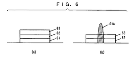
- Figs. 6a and 6b show two spectrums of a signal before and after the reverse diffusion taken place in the demodulating section 514 1 .
- Fig. 6a shows a spectrum before reverse diffusion
- Fig. 6b shows a spectrum after reverse diffusion.
- an uplink radio signal 61 is subjected to reverse diffusion in the demodulating section 514 1 but not the other two uplink radio signals 62 and 63.
- non-reverse-diffused uplink radio signals 62 and 63 disturb a signal 61A obtained by the reverse diffusion as a noise.
- a fiber-optic network based on passive double star (PDS) architecture is described.
- the system consists of three primary elements: a central base-station, micro base-stations and an operation and maintenance center.
- the central base-station and the micro base-station sites are connected by a fiber-optic link.
- a frequency up-converter and a frequency down-converter and a reference signal generator are used.
- Document EP 0 845 878 A2 discloses a transmission of CDMA signals over an analog optical link. Wireless signals are backhauled to a central base-station. Signal processing is performed at a remote antenna site. An RF drive current driving a laser transmitter is kept above a predetermined level to prevent noise caused by optical feedback into the laser transmitter.
- an objective of the present invention is to provide a multi-point optical transmission system, method and master station, in which, signals optically transmitted to and from a plurality of slave stations have high quality without a drop in the C/N ratio thereof, and to reduce noise and distortion that occur in the optical system.
- the present invention has the features of claim 1, claim 2 or claim 3, respectively, to attain the objective above.
- a first aspect is directed to a multi-point optical transmission system for optically transmitting code-division multiplex signals from a plurality of slave stations(10 1 to 10 n , 20 1 to 20 n , 30 1 to 30 n ) to a master station(11, 21, 31), the slave stations(10 1 to 10 n , 20 1 to 20 n , 30 1 to 30 n ) having each varied carrier frequency assigned, each of the slave stations(10 1 to 10 n , 20 1 to 20 n , 30 1 to 30 n ) comprising:
- each signal to be demodulated by the demodulation means(116 1 to 116 n ) includes only a code-division multiplex signal outputted from a single slave station(10 1 to 10 n , 20 1 to 20 n , 30 1 to 30 n ). Accordingly, a code-division multiplex signal outputted from a desired base station will not be disturbed by code-division multiplex signals outputted from the other stations as a noise any more.
- the multi-point optical transmission system of the present invention can successfully optically transmit code-division multiplex signals outputted from a plurality of slave stations (10 1 to 10 n , 20 1 to 20 n , 30 1 to 30 n ) to a master station(11, 21, 31) in a multi-point fashion without causing a drop in each C/N ratio thereof.
- a second aspect is directed to the multi-point optical transmission system as set forth in the first aspect of the invention, wherein each of the slave stations (10 1 to 10 n , 20 1 to 20 n , 30 1 to 30 n ) has varied downlink carrier frequency further assigned, the master station(11, 21, 31) further comprises:
- each downlink signal outputted from the master station(11, 21, 31) can further be optically transmitted to the slave stations (10 1 to 10 n , 20 1 to 20 n , 30 1 to 30 n ) in a multi-point fashion without a drop in each C/N ratio thereof.
- a third aspect of the present invention is directed to the multi-point optical transmission system as set forth in the second aspect of the invention, wherein each of the slave stations (10 1 to 10 n , 20 1 to 20 n , 30 1 to 30 n ) has varied pilot signal frequency further assigned, and further comprises pilot signal multiplex means(311) for multiplexing a pilot signal having a pilot signal frequency assigned to the own station on a code-division multiplex signal to be transmitted to the master station(11, 21, 31), the master station(11, 21, 31) further comprises downlink pilot signal multiplex means(311) for multiplexing a downlink pilot signal on each downlink signal to be transmitted to the slave stations(10 1 to 10 n , 20 1 to 20 n , 30 1 to 30 n ), the downlink pilot signal multiplex means(311) examines the electrical signal obtained after conversion by the optical-electrical conversion means to measure power of the pilot signal, and then generates control information indicating a difference between a measured value and a predetermined threshold to apply the same as a modul
- an amount of noise and distortion occurs in an optical transmission system is reduced by multiplexing a pilot signal into each code-division multiplex signal and a downlink pilot signal into each downlink signal.
- the system of the present invention suppresses noise-to-noise (power thereof) variation occurred in each code-division multiplex signal by equalizing each power thereof at the time of reaching the master station(11, 21, 31). As a result, the transmission characteristic of the system is improved.
- a fourth aspect is directed to the multi-point optical transmission system as set forth in the third aspect of the invention, wherein when converting the electrical signal into the optical signal, the electrical-optical conversion means(104) adjusts each optical modulation level of the optical signal to equalize the same.
- the equalized power of the optical signals to be transmitted to the optical-electrical conversion means (112) prevents a noise having a relative intensity from occurring only to a particular code-division multiplex signal. As a result, the transmission characteristic of the system is improved.
- a fifth aspect is directed to the multi-point optical transmission system as set forth in the third aspect of the invention, wherein each of the code-division multiplex signals is a signal into which a plurality of radio signals transmitted from a mobile station in each cell(12) of the slave stations(10 1 to 10 n , 20 1 to 20 n , 30 1 to 30 n ) are code-division-multiplexed, each downlink signal is a signal into which a plurality of radio signals to be transmitted to the mobile station in the cell (12) are multiplexed, and each of the slave stations (10 1 to 10 n , 20 1 to 20 n , 30 1 to 30 n ) further comprises:
- the slave stations (10 1 , to 10 n , 20 1 to 20 n , 30 1 to 30 n ) can respectively be downsized as the system does not require thereto to have two antennas for transmitting and receiving signals, respectively.
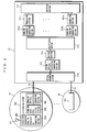
- Fig. 1 is a block diagram showing the structure of a multi-point optical transmission system according to a first embodiment of the present invention.
- the system in Fig. 1 comprises radio base stations 10 1 to 10 n (where n is an arbitrary integer of 2 or more) and a switching station 11, and each of the radio base stations 10 1 to 10 n is connected to the switching station 11 via an optical fiber 13.
- Each of the radio base stations 10 1 to 10 n comprises an antenna 101, an uplink frequency converting section 102, a driving section 103, and an uplink electrical-optical converting section 104.
- the switching section 11 comprises an optical multiplexing section 111, an uplink optical-electrical converting section 112, a branching section 113, uplink band pass filter sections 114 1 to 114 n , uplink frequency re-converting sections 115 1 to 115 n , demodulating sections 116 1 to 116 n , and a switching section 117.
- the antenna 101 receives an uplink radio signal.
- the uplink radio signal herein is a code-division multiplex signal into which radio signals outputted from a plurality of terminals not shown in each cell 12 are multiplexed in a code-division multiplex system.
- Each of the uplink radio signals is equal in frequency (f0) as predetermined.
- uplink radio signals are not necessarily equal in frequency.
- f0 frequency
- the radio base stations 10 1 to 10 n are assigned with each varied frequency (f1 to fn), and each uplink frequency converting section 102 in the radio base stations 10 1 to 10 n subjects the uplink radio signal to frequency conversion so as to equalize the frequency thereof with a frequency assigned to the own station.
- the driving section 103 applies a bias to the uplink radio signal.
- the uplink electrical-optical converting section 104 converts the uplink radio signal into an optical signal whose intensity is modulated by the uplink radio signal.
- the optical multiplexing section 111 multiplexes the optical signals outputted respectively from the radio base stations 10 1 to 10 n .
- the uplink optical-electrical converting section 112 converts an optical signal obtained after multiplexing into an electrical signal.
- the branching section 113 branches the electrical signal into n signals.
- the uplink band pass filter sections 114 1 to 114 n extract any uplink radio signal having frequency of f1 to fn from the electrical signal.
- the uplink frequency re-converting sections 115 1 to 115 n subject the uplink radio signals having frequency of f1 to fn to frequency re-conversion so as to convert each frequency thereof back to the original value of f0.
- the demodulating sections 116 1 to 116 n demodulate the uplink radio signals obtained after the re-conversion taken place in the uplink frequency re-converting sections 115 1 to 115 n to base band digital data.
- the switching section 117 goes through a switching process in accordance with the respective base band digital data.
- Each cell 12 in the system in Fig. 1 includes a plurality of terminals (not shown), and each of the terminals transmits a radio signal in a code-division multiplex system to one of the radio base stations 10 1 to 10 n located in the same cell 12.
- the radio signals outputted from the plurality of terminals are subjected to code-division multiplexing so as to obtain uplink radio signals.
- Each of the uplink radio signals is then received by the antenna 101 of each radio base station 10 1 to 10 n .
- the received uplink radio signals each having a frequency of f0 are subjected to frequency conversion in each uplink frequency converting section 102 so that each frequency thereof is converted into a predetermined value (f1 to fn) according to the respective radio base stations 10 1 to 10 n .
- the uplink radio signal obtained after the frequency conversion is biased in the driving section 103, and then sent to the uplink electrical-optical converting section 104.
- the uplink electrical-optical converting section 104 outputs an optical signal whose intensity is modulated by the uplink radio signal.
- the respective optical signals outputted from the radio base stations 10 1 to 10 n are transmitted to the switching station 11 via the optical fiber 13.
- the transmitted optical signals are multiplexed in the optical multiplexing section 111, and then a resultant signal is subjected to optical-electrical conversion in the uplink optical-electrical converting section 112.
- the electrical signal obtained by conversion is branched into n signals in the branching section 113, and then sent to the band pass filters 114 1 to 114 n .
- the band pass filters 114 1 to 114 n have a characteristic of selectively passing signals having frequency of f1 to fn. Therefore, uplink radio signals having frequency of f1 to fn are extracted from each electrical signal obtained after n-branching by each filter.
- the extracted uplink radio signals are respectively subjected to frequency re-conversion in the uplink frequency re-converting sections 115 1 to 115 n so that each frequency thereof is converted back to the original value of f0.
- Each uplink radio signal obtained after the re-conversion is demodulated to base band digital data in the demodulating sections 116 1 to 116 n , and sent to the switching section 117. Thereafter, the switching section 117 performs a switching process in accordance with the respective base band digital data.
- the radio base stations 10 1 to 10 n subject each uplink radio signal having the predetermined frequency of f0 to frequency conversion so as to vary each frequency thereof according to the radio base stations 10 1 to 10 n (f1 to fn), and then convert the uplink radio signals into optical signals before transmitting the same to the switching station 11.
- the switching station 11 on the other hand, multiplexes the optical signals outputted from the radio base stations 10 1 to 10 n , subjects a resultant optical signal to optical-electrical conversion, and extracts uplink radio signals respectively from the electrical signals obtained after the conversion.
- the switching station 11 subjects the extracted uplink radio signals each having frequency of f1 to fn to frequency re-conversion so as to convert each frequency thereof back to the original value of f0, and then demodulates the same to base band digital data.
- each signal to be demodulated in the demodulating sections 116 1 to 116 n allows each signal to be demodulated in the demodulating sections 116 1 to 116 n to include nothing but an uplink radio signal outputted from the radio base stations 10 1 to 10 n . Accordingly, a code-division multiplex signal outputted from a desired base station will not be bothered by uplink radio signals outputted from the other stations as a noise as will be in the system in Fig. 5.
- a plurality of uplink radio signals outputted from the radio base stations 10 1 to 10 n can be successfully optically transmitted to the switching station 11 in a multi-point manner without causing a drop in a C/N ratio thereof in the system in Fig. 1.
- Fig. 2 is a block diagram showing the structure of a multi-point optical transmission system according to a second embodiment of the present invention.
- the system in Fig. 2 includes radio base stations 20 1 to 20 n (where n is an arbitrary integer of 2 or more) and a switching station 21, and each of the radio base stations 20 1 to 20 n is connected to the switching station 21 via an optical fiber 13.
- the respective radio base stations 20 1 to 20 n further includes a downlink optical-electrical converting section 201, a downlink band pass filter section 202, a downlink frequency re-converting section 203, and a circulator 204 in addition to the components included in the radio base stations 10 1 to 10 n in Fig. 1 (Note that the components identical to those of the radio base stations 10 1 to 10 n are not shown in this drawing).
- the switching station 21 further includes modulating sections 211 1 to 211 n , downlink frequency converting sections 212 1 to 212 n , a multiplexing section 213, a driving section 214, a downlink electrical-optical converting section 215, and an optical branching section 216 in addition to the components included in the switching station 11 in Fig. 1 (Note that the components identical to those in the switching station 11 in Fig. 1 are not shown in this drawing except for the switching section 117).
- the modulating sections 211 1 to 211 n modulate each base band digital data to be transmitted to the radio base stations 20 1 to 20 n in a code-division multiplex system.
- the downlink frequency converting sections 212 1 to 212 n subject the downlink radio signals each having frequency of f'0 obtained after the modulation to frequency conversion so as to vary each frequency thereof to be f'1 to f'n.
- the multiplexing section 213 multiplexes the downlink radio signals.
- the driving section 214 applies a bias to an electrical signal.
- the downlink electrical-optical converting section 215 outputs an optical signal whose intensity is modulated by the electrical signal.
- the branching section 215 branches the optical signal into n signals.
- the downlink optical-electrical conversion 201 converts the optical signal into an electrical signal.
- the respective downlink band pass filter sections 202 extract downlink uplink signals having frequency of f'1 to f'n from the electrical signal.
- the downlink frequency re-converting section 203 subjects the downlink radio signals having frequency of f'1 to f'n so as to convert each frequency thereof back to the original value of f'0.
- an uplink radio signal received by the antenna 101 of the respective radio base stations 20 1 to 20 n is inputted to an uplink system via the circulator 204.
- the uplink radio signal is sent to a component corresponding to the uplink frequency converting section 102 in Fig. 1 so as to be optically transmitted to the switching station 21 in a multi-point fashion.
- the uplink radio signal is transmitted in the system is the same as in the above first embodiment, further description thereof is thus omitted below.
- the operation how downlink radio signals are optically transmitted from the switching station 21 to the radio base stations 20 1 to 20 n in a multi-point fashion is described next below.
- the respective base band digital data outputted from the switching section 117 to be transmitted to the radio base stations 20 1 to 20 n is modulated in the modulating sections 211 1 to 211 n in a code-division multiplex system.
- the respective downlink radio signals obtained by the modulation are equal in frequency (f'0) and are subjected to frequency conversion in the downlink frequency converting sections 212 1 to 212 n so that each frequency thereof is varied from f'1 to f'n.
- the downlink radio signals outputted form the modulating sections 212 1 to 212 n are not necessarily equal in frequency.
- the downlink radio signals obtained by the frequency conversion are multiplexed in the multiplexing section 213, biased in the driving section 214, and then sent to the downlink electrical-optical converting section 215.
- the downlink electrical-optical converting section 215 outputs an optical signal whose intensity is modulated by the electrical signal.
- the outputted optical signal is branched into n signals in the optical branching section 216, and the signals are then transmitted to the radio base stations 20 1 to 20 n via the optical fiber 13.
- the transmitted optical signals are converted into electrical signals in each downlink optical-electrical converting section 201.
- each band pass filter section 202 has a characteristic of selectively passing signals having frequency of f'1 to f'n, downlink radio signals each having frequency of f'1 to f'n are extracted from each electrical signal by each filter.
- the extracted downlink radio signals each are subjected to frequency re-conversion so that each frequency thereof is converted back to the original value of f'0. Thereafter, the signals are sent to the antenna 101 through the optical circulator 204 so as to be transmitted to a plurality of terminals (not shown) in each cell 12.
- the switching station 21 subjects the downlink radio signals each having the predetermined frequency of f'0 to frequency conversion so as to vary each frequency thereof from f'1 to f'n, multiplexes the signals, and converts the electrical signal obtained after conversion into an optical signal before transmitting the same to the radio base stations 20 1 to 20 n .
- each radio base station 20 1 to 20 n subjects the optical signal outputted from the switching station 21 to electrical-optical conversion, and extracts its own downlink radio signal having frequency of f'1 to f'n from the electrical signal obtained by the conversion. Thereafter, each radio base station 20 1 to 20 n subjects the extracted downlink radio signal is subjected to frequency re-conversion so as to convert the frequency thereof back to the original value of f'0 before transmitting the radio signal to each terminal located in the same cell 12.
- the system in Fig. 2 as well as the system in Fig. 1 can perform multi-point optical transmission with only a single uplink optical-electrical converting section 112 provided in the switching station 21 on a plurality of signals outputted from the radio base stations 20 1 to 20 n to the switching station 21 without causing a drop in each C/N ratio thereof. Further, the system can optically transmit a plurality of downlink radio signals outputted from the switching station 21 to the radio base stations 20 1 to 20 n in a multi-point manner without causing a drop in each C/N ratio thereof.
- the antenna for transmitting/receiving signals 101 and the circulator 204 provided in the radio base stations 20 1 to 20 n in the system in Fig. 2 can be substituted with two antennas for transmitting and receiving signals, respectively. In that case, however, the size of the radio base stations 20 1 to 20 n will be larger.
- Fig. 3 is a block diagram showing the configuration of a multi-point optical transmission system according to a third embodiment of the present invention.
- the system in Fig. 3 includes radio base stations 30 1 to 30 n (where n is an arbitrary integer of 2 or more; radio base stations 30 1 to 30 n are not shown in the drawing) and a switching station 31, and each of the radio base stations 30 1 to 30 n is connected to the switching station 31 via an optical fiber 13.
- Each of the radio base stations 30 1 to 30 n includes an antenna 101, an uplink frequency converting section 102, a driving section 103, an uplink electrical-optical converting section 104, a downlink optical-electrical converting section 201, a downlink band pass filter section 202, a downlink frequency re-converting section 203, a circulator 204, and an uplink pilot signal multiplexing section 301.
- the switching station 31 includes an optical multiplexing section 111, an uplink optical-electrical converting section 112, a branching section 113, uplink band pass filter sections 114 1 to 114 n , uplink frequency re-converting sections 115 1 to 115 n , demodulating sections 116 1 to 116 n , a switching section 117, modulating sections 211 1 to 211 n , downlink frequency converting sections 212 1 to 212 n , a multiplexing section 213, a driving section 214, a downlink frequency converting sections 215, an optical branching section 216, and a downlink pilot signal multiplexing section 311.
- the respective radio base stations 30 1 to 30 n included in the system in Fig. 3, are realized by additionally providing the uplink pilot signal multiplexing section 301 to each of the radio base stations 20 1 to 20 n and the switching station 31 is realized by additional providing the downlink pilot signal multiplexing section 311 to the switching station 21.
- the uplink pilot multiplexing section 301 multiplexes an uplink pilot signal into an uplink radio signal.
- the uplink pilot signals to be multiplexed are varied in frequency according to the radio base stations 30 1 to 30 n .
- the reason for the uplink radio signal having each different frequency is to help the switching station 31 identify which uplink pilot signal is outputted from which radio base station 30 1 to 30 n .
- the branching section 113 in Fig. 3 branches an electrical signal into n+1 signals.
- the downlink pilot signal multiplexing section 311 multiplexes a downlink pilot signal into a downlink radio signal.
- the downlink pilot signal multiplexing section 311 examines one of the electrical signals obtained after branching by the branching section 113 so as to measure power of each uplink pilot signal outputted from the radio base stations 30 1 to 30 n , and then compares the measured value and a predetermined reference value so as to provide the difference thereof as a modulation component to the respective downlink pilot signals to be multiplexed.
- the downlink band pass filter section 202 further extracts a downlink pilot signal from the electrical signal in addition to the tasks performed in the downlink band pass filter section 202 in Fig. 2 (refer to a second embodiment).
- the driving section 103 in addition to the tasks performed in the driving section 103 in Fig. 2, further adjusts power of a bias to be applied in accordance with the information provided to the downlink pilot signal extracted by the downlink band pass filter section 202 so that each power of the uplink pilot signals at the time of reaching the switching station 31 coincides with the reference value.
- the basic manners for multi-point optical transmission on a plurality of uplink radio signals from the base radio stations 30 1 to 30 n to the switching station 31, and on a plurality of downlink radio signals outputted from the switching station 31 to the radio base stations 30 1 to 30 n are similar to the respective manners in the system in Fig. 2. Therefore, further description of those manners is omitted but any difference between the two systems will be described in detail.
- Fig. 3 The system in Fig. 3 is differed from the one in Fig. 2 in the following two points.
- the first difference is that, in the system in Fig. 3, the uplink pilot signal multiplexing section 301 multiplexes an uplink pilot signal on an uplink radio signal, and the downlink pilot signal multiplexing section 311 multiplexes a downlink pilot signal on a downlink radio signal.
- the second difference is that power of each pilot signal outputted from the radio base stations 30 1 to 30 n is monitored in the switching station 31, and the monitored value is fed back to the radio base stations 30 1 to 30 n with the downlink pilot signal.
- the radio base stations 30 1 to 30 n adjust power of a bias to be applied to an uplink radio signal in accordance with the fed-back monitored value so that the power of the uplink pilot signal at the time of reaching the switching station 31 coincides with the predetermined reference value.
- the uplink radio signals will be equal in power to be sent to the demodulating sections 116 1 to 116 n .
- noise and distortion will be prevented from occurring only to an uplink radio signal outputted from a particular radio base station, and transmission characteristics in the system is accordingly improved.
- the system in Fig. 3 not only reduces an amount of noise and distortion occurred in an optical transmission system by multiplexing a pilot signal on a radio signal but prevents noise and distortion from occurring only to an uplink signal outputted from a particular radio base station by performing feedback control with the pilot signal so as to equalize power of the uplink radio signals to be sent to the demodulating sections 116 1 to 116 n .
- each driving section 103 in this embodiment adjusts power of a bias to be applied to an uplink radio signal so as to coincide power of each uplink pilot signal at the time of reaching the switching station 31 with the reference value.
- the uplink electrical-optical converting section 104 may adjust an optical modulation level of the optical signal in place of the respective driving sections 103.
- each intensity of the optical signals to be transmitted to the uplink optical-electrical converting section 112 may also be different from one another. Therefore, a noise-to-noise (power thereof) variation may be expected after the electrical-optical conversion, which is occurred due to a noise with a relative intensity contained in the optical signals respectively outputted from the electrical-optical converting sections 104.
- the optical signals to be transmitted to the uplink optical-electrical converting section 112 are equal in intensity, the amount of the noise will be minimum. Accordingly, if the optical modulation level of the optical signals is adjusted in the above manner, the transmission characteristic of the system will be degraded compared to best condition.
- the transmission characteristic will be preferably improved if, when the optical signals outputted from the respective uplink electrical-optical converting sections 104 are received by the uplink optical-electrical converting section 112, the respective driving sections 10 adjust power of a bias to be applied to the uplink radio signal so as to equalize the power of the optical signals before the respective uplink electrical-optical converting sections 104 adjust the optical modulation levels of the optical signals to be transmitted to equalize with one another.
Landscapes
- Engineering & Computer Science (AREA)
- Computer Networks & Wireless Communication (AREA)
- Signal Processing (AREA)
- Physics & Mathematics (AREA)
- Electromagnetism (AREA)
- Optical Communication System (AREA)
- Mobile Radio Communication Systems (AREA)
Priority Applications (4)
| Application Number | Priority Date | Filing Date | Title |
|---|---|---|---|
| JP32787897A JP3974984B2 (ja) | 1997-11-28 | 1997-11-28 | マルチポイント光送信システム |
| US09/320,144 US6392770B1 (en) | 1997-11-28 | 1999-05-26 | Multi-point optical transmission system |
| DE69933756T DE69933756T2 (de) | 1999-05-27 | 1999-05-27 | Mehrpunkte optische Verbindung in einem zellularen Funksystem mit CDMA Signalen |
| EP99109293A EP1056227B1 (en) | 1997-11-28 | 1999-05-27 | Multi-point optical link in a cellular radio system for CDMA signals |
Applications Claiming Priority (3)
| Application Number | Priority Date | Filing Date | Title |
|---|---|---|---|
| JP32787897A JP3974984B2 (ja) | 1997-11-28 | 1997-11-28 | マルチポイント光送信システム |
| US09/320,144 US6392770B1 (en) | 1997-11-28 | 1999-05-26 | Multi-point optical transmission system |
| EP99109293A EP1056227B1 (en) | 1997-11-28 | 1999-05-27 | Multi-point optical link in a cellular radio system for CDMA signals |
Publications (2)
| Publication Number | Publication Date |
|---|---|
| EP1056227A1 EP1056227A1 (en) | 2000-11-29 |
| EP1056227B1 true EP1056227B1 (en) | 2006-10-25 |
Family
ID=27239964
Family Applications (1)
| Application Number | Title | Priority Date | Filing Date |
|---|---|---|---|
| EP99109293A Expired - Lifetime EP1056227B1 (en) | 1997-11-28 | 1999-05-27 | Multi-point optical link in a cellular radio system for CDMA signals |
Country Status (3)
| Country | Link |
|---|---|
| US (1) | US6392770B1 (enExample) |
| EP (1) | EP1056227B1 (enExample) |
| JP (1) | JP3974984B2 (enExample) |
Families Citing this family (17)
| Publication number | Priority date | Publication date | Assignee | Title |
|---|---|---|---|---|
| US6792289B1 (en) * | 1999-11-08 | 2004-09-14 | Qualcomm Incorporated | Non-bandlimiting antenna sharing method and apparatus for base stations |
| JP3594862B2 (ja) * | 1999-12-28 | 2004-12-02 | 株式会社エヌ・ティ・ティ・ドコモ | 無線基地局システム、統括局及び該統括局における信号処理方法 |
| JP4624603B2 (ja) * | 2000-06-29 | 2011-02-02 | パナソニック株式会社 | 無線アクセス用光伝送システム及び高周波光送信器 |
| KR20010000755A (ko) * | 2000-10-17 | 2001-01-05 | 이진섭 | Cdma용 디지털 신호 분배 통신시스템 |
| US20040017785A1 (en) * | 2002-07-16 | 2004-01-29 | Zelst Allert Van | System for transporting multiple radio frequency signals of a multiple input, multiple output wireless communication system to/from a central processing base station |
| WO2004059934A1 (en) | 2002-12-24 | 2004-07-15 | Pirelli & C. S.P.A. | Radio base station receiver having digital filtering and reduced sampling frequency |
| KR100617839B1 (ko) * | 2004-11-16 | 2006-08-28 | 삼성전자주식회사 | 양방향 무선 통신을 위한 광 네트워크 |
| US9525488B2 (en) | 2010-05-02 | 2016-12-20 | Corning Optical Communications LLC | Digital data services and/or power distribution in optical fiber-based distributed communications systems providing digital data and radio frequency (RF) communications services, and related components and methods |
| US20110268446A1 (en) | 2010-05-02 | 2011-11-03 | Cune William P | Providing digital data services in optical fiber-based distributed radio frequency (rf) communications systems, and related components and methods |
| EP2606707A1 (en) | 2010-08-16 | 2013-06-26 | Corning Cable Systems LLC | Remote antenna clusters and related systems, components, and methods supporting digital data signal propagation between remote antenna units |
| US9252874B2 (en) | 2010-10-13 | 2016-02-02 | Ccs Technology, Inc | Power management for remote antenna units in distributed antenna systems |
| CN203504582U (zh) | 2011-02-21 | 2014-03-26 | 康宁光缆系统有限责任公司 | 一种分布式天线系统及用于在其中分配电力的电源装置 |
| US10659163B2 (en) | 2014-09-25 | 2020-05-19 | Corning Optical Communications LLC | Supporting analog remote antenna units (RAUs) in digital distributed antenna systems (DASs) using analog RAU digital adaptors |
| WO2016071902A1 (en) | 2014-11-03 | 2016-05-12 | Corning Optical Communications Wireless Ltd. | Multi-band monopole planar antennas configured to facilitate improved radio frequency (rf) isolation in multiple-input multiple-output (mimo) antenna arrangement |
| WO2016075696A1 (en) | 2014-11-13 | 2016-05-19 | Corning Optical Communications Wireless Ltd. | Analog distributed antenna systems (dass) supporting distribution of digital communications signals interfaced from a digital signal source and analog radio frequency (rf) communications signals |
| WO2016098109A1 (en) | 2014-12-18 | 2016-06-23 | Corning Optical Communications Wireless Ltd. | Digital interface modules (dims) for flexibly distributing digital and/or analog communications signals in wide-area analog distributed antenna systems (dass) |
| WO2016098111A1 (en) | 2014-12-18 | 2016-06-23 | Corning Optical Communications Wireless Ltd. | Digital- analog interface modules (da!ms) for flexibly.distributing digital and/or analog communications signals in wide-area analog distributed antenna systems (dass) |
Family Cites Families (7)
| Publication number | Priority date | Publication date | Assignee | Title |
|---|---|---|---|---|
| JP2897492B2 (ja) | 1991-10-24 | 1999-05-31 | 日本電気株式会社 | 移動通信装置 |
| JPH07283787A (ja) | 1994-04-07 | 1995-10-27 | Matsushita Electric Ind Co Ltd | ビート妨害防止方法 |
| DE69614284T2 (de) * | 1995-02-02 | 2002-01-10 | Nippon Telegraph And Telephone Corp., Tokio/Tokyo | Verzerrungskorrekturvorrichtung |
| DE19605567A1 (de) | 1996-02-15 | 1997-08-21 | Sel Alcatel Ag | Optisches frequenzkodiertes CDMA-Übertragungssystem und optischer Empfänger dafür |
| US5936754A (en) | 1996-12-02 | 1999-08-10 | At&T Corp. | Transmission of CDMA signals over an analog optical link |
| JPH1127739A (ja) | 1997-07-04 | 1999-01-29 | Mitsubishi Electric Corp | 基地局間接続装置 |
| SE523374C2 (sv) | 1997-07-31 | 2004-04-13 | Ericsson Telefon Ab L M | Kommunikation med hjälp av spektrumspridningsmetoder över optiska fibrer |
-
1997
- 1997-11-28 JP JP32787897A patent/JP3974984B2/ja not_active Expired - Lifetime
-
1999
- 1999-05-26 US US09/320,144 patent/US6392770B1/en not_active Expired - Lifetime
- 1999-05-27 EP EP99109293A patent/EP1056227B1/en not_active Expired - Lifetime
Non-Patent Citations (1)
| Title |
|---|
| CHEONG J.M. ET AL: "Field Trial Experiment of CDMA Fiber-Optic Microcellular System: FoMiCell", OFC/IOOC'99, 21 February 1999 (1999-02-21), SAN DIEGO, pages PD13.1 - PD13.3 * |
Also Published As
| Publication number | Publication date |
|---|---|
| EP1056227A1 (en) | 2000-11-29 |
| JP3974984B2 (ja) | 2007-09-12 |
| JPH11163834A (ja) | 1999-06-18 |
| US6392770B1 (en) | 2002-05-21 |
Similar Documents
| Publication | Publication Date | Title |
|---|---|---|
| US8855489B2 (en) | Communications method, particularly for a mobile radio network | |
| EP2180614B1 (en) | Optical line terminal, passive optical network and radio frequency signal transmission method | |
| JP4063419B2 (ja) | 光伝送システム | |
| Smith et al. | A millimeter-wave full-duplex fiber-radio star-tree architecture incorporating WDM and SCM | |
| US6392770B1 (en) | Multi-point optical transmission system | |
| EP1173034B1 (en) | Mobile communication network system using digital optical link | |
| JP6532747B2 (ja) | コヒーレント・ネットワークmimoのためのアンテナ同期 | |
| KR100443312B1 (ko) | 무선 기지국 네트워크 시스템 및 기지국 전환 방법 | |
| DE60032447T2 (de) | Funkbasisstationssystem und zentrale Steuerungsstation mit einheitlichem Übertragungsformat | |
| US10027415B2 (en) | Apparatuses and methods for transmitting and receiving control signal in analog radio-over-fiber (ROF)-based mobile fronthaul | |
| Kuri et al. | Dense wavelength-division multiplexing millimeter-wave-band radio-on-fiber signal transmission with photonic downconversion | |
| GB2256114A (en) | Apparatus and method for synchronizing a plurality of remote transmission and receiving stations | |
| KR20010109174A (ko) | 송신 다이버시티를 갖는 코드-분할, 다중-접속 기지국 | |
| CN103401612A (zh) | 基于ftth网络的光纤和无线混合接入系统及混合接入方法 | |
| AU711362B2 (en) | Communication system for multicasting delay-adjusted signals on same radio frequencies to adjoining cells | |
| JPH11163834A5 (enExample) | ||
| CN110651437B (zh) | 基站装置、地面站装置和地面天线装置 | |
| US7668463B2 (en) | Method and apparatus for generating and transmitting WDM MWOF signals | |
| US20030154497A1 (en) | Optical coaxial hybrid transmission system | |
| JPH0448832A (ja) | 光リンク無線通信方式 | |
| JP2001156720A (ja) | 光伝送システムおよび光伝送方法 | |
| CN115426010B (zh) | 一种5g mimo信号传输系统及方法 | |
| JP4696270B2 (ja) | 通信システム及び通信方法 | |
| KR20000055045A (ko) | 다목적 광섬유 액세스 망 | |
| KR102398348B1 (ko) | 분산 안테나 시스템 |
Legal Events
| Date | Code | Title | Description |
|---|---|---|---|
| PUAI | Public reference made under article 153(3) epc to a published international application that has entered the european phase |
Free format text: ORIGINAL CODE: 0009012 |
|
| AK | Designated contracting states |
Kind code of ref document: A1 Designated state(s): DE FR GB |
|
| AX | Request for extension of the european patent |
Free format text: AL;LT;LV;MK;RO;SI |
|
| 17P | Request for examination filed |
Effective date: 20001220 |
|
| AKX | Designation fees paid |
Free format text: DE FR GB |
|
| 17Q | First examination report despatched |
Effective date: 20020603 |
|
| GRAP | Despatch of communication of intention to grant a patent |
Free format text: ORIGINAL CODE: EPIDOSNIGR1 |
|
| GRAS | Grant fee paid |
Free format text: ORIGINAL CODE: EPIDOSNIGR3 |
|
| GRAA | (expected) grant |
Free format text: ORIGINAL CODE: 0009210 |
|
| AK | Designated contracting states |
Kind code of ref document: B1 Designated state(s): DE FR GB |
|
| REG | Reference to a national code |
Ref country code: GB Ref legal event code: FG4D |
|
| REF | Corresponds to: |
Ref document number: 69933756 Country of ref document: DE Date of ref document: 20061207 Kind code of ref document: P |
|
| ET | Fr: translation filed | ||
| PLBE | No opposition filed within time limit |
Free format text: ORIGINAL CODE: 0009261 |
|
| STAA | Information on the status of an ep patent application or granted ep patent |
Free format text: STATUS: NO OPPOSITION FILED WITHIN TIME LIMIT |
|
| 26N | No opposition filed |
Effective date: 20070726 |
|
| REG | Reference to a national code |
Ref country code: FR Ref legal event code: PLFP Year of fee payment: 17 |
|
| PGFP | Annual fee paid to national office [announced via postgrant information from national office to epo] |
Ref country code: GB Payment date: 20150527 Year of fee payment: 17 Ref country code: DE Payment date: 20150519 Year of fee payment: 17 |
|
| PGFP | Annual fee paid to national office [announced via postgrant information from national office to epo] |
Ref country code: FR Payment date: 20150508 Year of fee payment: 17 |
|
| REG | Reference to a national code |
Ref country code: DE Ref legal event code: R119 Ref document number: 69933756 Country of ref document: DE |
|
| GBPC | Gb: european patent ceased through non-payment of renewal fee |
Effective date: 20160527 |
|
| REG | Reference to a national code |
Ref country code: FR Ref legal event code: ST Effective date: 20170131 |
|
| PG25 | Lapsed in a contracting state [announced via postgrant information from national office to epo] |
Ref country code: DE Free format text: LAPSE BECAUSE OF NON-PAYMENT OF DUE FEES Effective date: 20161201 Ref country code: FR Free format text: LAPSE BECAUSE OF NON-PAYMENT OF DUE FEES Effective date: 20160531 |
|
| PG25 | Lapsed in a contracting state [announced via postgrant information from national office to epo] |
Ref country code: GB Free format text: LAPSE BECAUSE OF NON-PAYMENT OF DUE FEES Effective date: 20160527 |