EP1056113A2 - Ion implanter and a method of implanting ions - Google Patents
Ion implanter and a method of implanting ions Download PDFInfo
- Publication number
- EP1056113A2 EP1056113A2 EP00303209A EP00303209A EP1056113A2 EP 1056113 A2 EP1056113 A2 EP 1056113A2 EP 00303209 A EP00303209 A EP 00303209A EP 00303209 A EP00303209 A EP 00303209A EP 1056113 A2 EP1056113 A2 EP 1056113A2
- Authority
- EP
- European Patent Office
- Prior art keywords
- ions
- energy
- electrodes
- electrode
- gap
- Prior art date
- Legal status (The legal status is an assumption and is not a legal conclusion. Google has not performed a legal analysis and makes no representation as to the accuracy of the status listed.)
- Withdrawn
Links
Images







Classifications
-
- H—ELECTRICITY
- H01—ELECTRIC ELEMENTS
- H01J—ELECTRIC DISCHARGE TUBES OR DISCHARGE LAMPS
- H01J37/00—Discharge tubes with provision for introducing objects or material to be exposed to the discharge, e.g. for the purpose of examination or processing thereof
- H01J37/30—Electron-beam or ion-beam tubes for localised treatment of objects
- H01J37/317—Electron-beam or ion-beam tubes for localised treatment of objects for changing properties of the objects or for applying thin layers thereon, e.g. for ion implantation
- H01J37/3171—Electron-beam or ion-beam tubes for localised treatment of objects for changing properties of the objects or for applying thin layers thereon, e.g. for ion implantation for ion implantation
-
- H—ELECTRICITY
- H01—ELECTRIC ELEMENTS
- H01J—ELECTRIC DISCHARGE TUBES OR DISCHARGE LAMPS
- H01J2237/00—Discharge tubes exposing object to beam, e.g. for analysis treatment, etching, imaging
- H01J2237/04—Means for controlling the discharge
- H01J2237/047—Changing particle velocity
- H01J2237/0473—Changing particle velocity accelerating
- H01J2237/04735—Changing particle velocity accelerating with electrostatic means
- H01J2237/04737—Changing particle velocity accelerating with electrostatic means radio-frequency quadrupole [RFQ]
Definitions
- the invention is concerned with ion implanters and with a method of ion implantation.
- Ion implanters have been used for many years in the processing of semiconductor wafers. Typically, a beam of ions of a required species is produced and directed at a wafer or other semiconductor substrate, so that ions become implanted under the surface of the wafer. Implantation is typically used for producing regions in the semiconductor wafer of altered conductivity state, by implanting in the wafer ions of a required dopant. Typical ionic species used for this purpose are boron, phosphorus, arsenic and antimony. However, other ionic species are also used for other purposes, including oxygen for example.
- the depth to which implanted ions penetrate the surface of the wafer is largely dependent on the energy of the ions in the ion beam.
- the semiconductor industry requires both very shallow implants, for example for very fine structures having a small feature size, and relatively deep implants, for example for buried layers etc. It is also a general requirement of the semiconductor processing industry that process times should be as short as possible which implies that the quantity of ions being implanted per unit area and time into a semiconductor wafer should be as high as possible. This implies that ion implantation is conducted with a high beam current, being a measure of the number of required ions in the beam reaching the wafer surface per unit time.
- Beam energies up to about 200 keV can quite readily be obtained using electrostatic acceleration systems, in which the source of ions is held at a fixed voltage relative to the wafer to be implanted, the fixed voltage defining the energy of the ions in the beam on implantation.
- radio frequency linear accelerators are useful to achieve higher beam energies.
- a linear accelerator structure accelerates charged particles of a specific mass/charge ratio which are injected into the accelerator at a specific injection energy. It is the inherent nature of rf linear accelerators that the particles or bunches of particles passing through the accelerator must reach successive accelerating gaps at the right region of the sinusoidal waveform of the voltage applied to the gaps. Essentially, as each particle (or bunch of particles) crosses an accelerating cavity it will receive a certain amount of energy (increase in speed) dependent on the field across the gap at the specific time. If an accelerator is set up for particles of a particular mass/charge ratio and injection energy, the particles accelerated by a first gap will reach the next accelerating gap just as the field across that gap is optimum to provide further acceleration.
- Japanese Patent Application Publication No. Hei 9-237700 discloses an ion implanter using an rf accelerator formed with one or more three gap rf accelerator cavities.
- a two gap accelerator cavity e.g. as used by the above referred U.S. patent, has entrance and exit electrodes at a fixed, usually ground, potential and a single intermediate electrode to which is applied the rf potential, thereby forming a pair of accelerating gaps on opposite sides of the rf electrode.
- a three gap cavity has entrance and exit electrodes at a fixed, usually ground, potential and a pair of intermediate electrodes defining three gaps.
- the intermediate electrodes are energised by the rf potential with opposite polarity.
- the amplitude of the energising rf voltage is V
- the maximum accelerating potential across the first and last gaps of the cavity is V
- the maximum accelerating potential between the two intermediate electrodes is 2V.
- the invention provides an ion implanter comprising an ion beam generator for generating a beam of ions to be implanted in which said ions are at a first energy, and a radio frequency linear accelerator assembly arranged when energised for accelerating ions of said beam to a second energy, said assembly comprising electrodes defining a series of gaps for changing the energy of ions of said beam, said electrodes having apertures through which the ions pass, wherein the apertures of the electrodes defining the gaps of the accelerator assembly have respective first dimensions in a first orthogonal direction transverse to the beam direction and respective second dimensions in a second orthogonal direction transverse to the beam direction, said first dimension of the aperture of at least a first electrode defining a first gap of said series being smaller than said second dimension of said first electrode aperture.
- the assembly is preferably formed of at least one three gap linear accelerator stage.
- a linear accelerator formed of three gap cavities can be shorter overall for the same energy increment as will be provided by an equivalent accelerator formed of two gap cavities.
- the invention also provides an ion implanter comprising an ion beam generator for generating a beam of ions to be implanted, in which said ions have a predetermined mass/charge ratio and an injection energy E, a three gap linear accelerator stage into which said beam of ions is directed at said injection energy, said stage being arranged when energised for accelerating ions of said beam to a second energy, said stage comprising an entrance electrode held at a fixed potential and an exit electrode held at a fixed potential, first and second radio frequency electrodes located in series between said entrance and exit electrodes, and a radio frequency generator to apply radio frequency voltages of opposite polarity and a predetermined frequency f respectively to said first and second electrodes, said entrance electrode and said first radio frequency electrode defining a first accelerating gap, said first and second radio frequency electrodes defining a second accelerating gap having a centre point at a first predetermined spacing d 1 from the centre point of the first gap, and said second radio frequency electrode and said exit electrode defining a third accelerating gap having a
- the accelerator should be driven and structured so that bunches of ions passing along the length of the accelerator arrive at each accelerating gap at or shortly before the peak of the rf field across that gap which would produce maximum acceleration.
- bunches of ions passing along the length of the accelerator arrive at each accelerating gap at or shortly before the peak of the rf field across that gap which would produce maximum acceleration.
- the variation in field strength experienced by ions in the bunch arriving at different times tends to provide greater acceleration to ions arriving late in the bunch, and less acceleration to ions arriving first in the bunch.
- the bunching tendency is maintained as the ions pass through the accelerator.
- the third gap may not so effectively remove the energy spread.
- such ions would also have reduced spread in phase when crossing the second gap,so that the energy spread introduced by the second gap would be reduced.
- the overall effect would be a similar reduction in overall percentage energy spread in the ions leaving the accelerator stage.
- such an arrangement allows the stage to be used with different applied radio frequency voltage amplitudes. Reducing the rf amplitude from the maximum has the effect of reducing the energy increment delivered to the beam ions passing through the stage.
- the proportion of injected ions passing through the accelerator stage and accelerated to the target energy is maintained over a wide range of applied rf voltages. This allows the accelerator stage to be operated for delivering a range of energy increments to the injected ion beam while still maintaining good beam current in the accelerated beam.
- the invention also provides an ion implanter comprising an ion beam generator for generating a beam of ions to be implanted in which said ions are at a first energy, and a radio frequency linear accelerator assembly arranged when energised for accelerating ions of said beam to a second energy, said assembly comprising a housing, electrodes mounted in the housing, said electrodes defining a series of gaps for changing the energy of ions of said beam, said electrodes having apertures through which the ions pass, at least one inductive coil electrically connected to at least one of said electrodes for energising said at least one electrode at a radio frequency potential, and an electrically conductive enclosure around said coil, said coil, said at least one electrode, said housing and said conductive enclosure together constituting a radio frequency tank circuit having a predetermined resonant frequency, said coil comprising a self supporting rigid electrical conductor having at least first and second connecting arms, said linear accelerator assembly including a coil mounting fixture on said electrically conductive enclosure arranged to receive said first connecting arm for electrical connection
- the invention also provides an ion implanter comprising an ion beam generator for generating a beam of ions to be implanted in which said ions are at a first energy, and a radio frequency linear accelerator assembly arranged when energised for accelerating ions of said beam to a second energy, said assembly comprising a housing, electrodes mounted in the housing, said electrodes defining a series of gaps for changing the energy of ions of said beam, said electrodes having apertures through which the ions pass, at least one inductive coil electrically connected to at least one of said electrodes for energising said at least one electrode at a radio frequency potential, and an electrically conductive enclosure around said coil, said coil, said at least one electrode, said housing and said conductive enclosure together constituting a radio frequency tank circuit having a predetermined resonant frequency, said coil comprising a tubular electrical conductor having an open end and a closed end, said linear accelerator assembly including a connecting fixture on said electrically conductive enclosure to receive said open end to enable access to said open end
- the invention also provides an ion implanter comprising an ion beam generator for generating a beam of ions to be implanted in which said ions are at a first energy, and a radio frequency linear accelerator assembly arranged when energised for accelerating ions of said beam to a second energy, said assembly comprising electrodes defining a series of gaps for changing the energy of ions of said beam, said electrodes having apertures through which the ions pass, and at least one magnetic quadrupole located along the beam adjacent at least one of said electrodes for controlling beam divergence, said assembly further comprising a unitary block providing a vacuum housing for the assembly, said unitary block having a through channel for said beam to pass through, a plurality of electrode mounting points for mounting said electrodes to define a plurality of said gaps along the length of said through channel, and at least one magnetic quadrupole mounting point for mounting said magnetic quadrupole.
- the invention still further provides a method of implanting ions into a target substrate comprising the steps of generating a beam of the ions at a first energy, and changing the energy of ions in the beam to a second energy using a radio frequency (rf) linear accelerator assembly having at least first and second booster stages in tandem along the beam direction, each of the booster stages comprising entrance and exit electrodes and at least one intermediate rf electrode defining a series of gaps for changing the energy of ions of said beam, the exit electrode of the first booster stage and the entrance electrode of the second booster stage defining between them a drift distance between the stages over which beam ions are not subject to rf fields, wherein the speed of the bunches of ions from the first booster stage over said drift distance to the second booster stage, and thus the flight time, is adjusted, while locking the phase of the field at each stage to a respective fixed value.
- rf radio frequency
- One way of achieving this is by adjusting the amplitude of the rf fields in the first booster stage, thereby adjusting the energy, i.e. speed, of the bunches exiting the first booster.
- the set up of the linear accelerator may be changed from accelerating a beam of ions of a first mass/charge ratio to accelerating a beam of ions of a second mass/charge ratio by changing ion speed over the drift distance while maintaining the respective phases of the rf fields in the first and second booster stages locked.
- the set up of the accelerator can easily be changed for accelerating ions of different mass charge ratios.
- the drift distance is greater than the length of the first booster stage between the entrance and exit electrodes thereof. Then, a relatively modest change in the speed (energy) of the bunches of ions exiting the first booster stage can have a substantial effect on the time of arrival of the bunches at the second booster stage.
- the present invention provides an ion implanter comprising an ion beam generator for generating a beam of ions to be implanted, in which said ions are at a first energy, and a radio frequency (rf) linear accelerator assembly arranged, when energised, for accelerating ions of said beam to a second energy, said assembly comprising at least first and second resonant cavities in tandem along the beam direction, said cavities comprising electrodes defining a series of gaps for changing the energy of ions of said beam, a rf power supply to provide a first supply of rf energy at a first frequency to said first cavity, said first cavity being resonant at said first frequency, whereby to produce corresponding first rf accelerating fields between electrode gaps in said first cavity, said first fields having a phase and an amplitude, said rf power supply providing a second supply of rf energy at a second frequency, which is the same as or a harmonic of said first frequency, to said second cavity, said second cavity being reson
- the present invention further provides an ion implanter comprising an ion beam generator for generating a beam of ions to be implanted in which said ions are at a first energy, and a radio frequency linear accelerator assembly arranged when energised for accelerating ions of said beam to a second energy, said assembly comprising first and second rf booster stages in tandem along the beam direction, each of said booster stages comprising entrance and exit electrodes and at least one intermediate rf electrode defining a series of gaps for changing the energy of the ions of said beam, and an adjacent pair of magnetic quadrupoles located between said first and second booster stages, said electrodes having apertures through which the ions pass, all the electrodes of said first and second booster stages being contained in a length L and the apertures of the electrodes having respective largest dimensions transverse to the beam which are not less than D, where L/D is less than 25.
- the present invention further provides a method of operating a three gap radio frequency (rf) accelerator stage for accelerating ions of a selected mass/charge ratio (m/e) from an injection energy E to a second energy, comprising providing the accelerator stage to be energisable with an rf voltage having a maximum amplitude A without breakdown occurring, applying an rf voltage of frequency f to generate corresponding rf accelerating fields in the accelerator stage, and selecting the injection energy E, the frequency f and the spacings d 1 and d 2 between the centres of the first and second gaps and between the second and third gaps respectively of the accelerator stage, such that, with the rf voltage amplitude not greater than A, said ions cross the first gap when the radio frequency field across the first gap is rising from a maximum deceleration field to a maximum acceleration field, then cross the second gap during the maximum acceleration field across the second gap and cross the third gap when the field across the third gap is falling from a maximum acceleration field to a maximum deceleration field.
- rf radio frequency
- the present invention further provides apparatus for generating a beam of ions of a selected mass/charge ratio and a desired energy for implantation in a substrate, the apparatus comprising an ion source providing a beam of ions at a first energy, an analyser magnet which receives said beam of ions at said first energy and spacially resolves ions of said beam at a resolving plane transverse to the beam direction, in accordance with the momentum of said ions, a first three gap linear accelerator cavity having an entrance electrode located adjacent said resolving plane so that ions of selected momentum from said beam are injected into said first cavity at said first energy, a second three gap linear accelerator cavity to receive ions from said first cavity, and a pair of magnetic quadrupoles between said first and second cavities for controlling spreading of ions passing through said cavities.
- the present invention further provides an ion implanter comprising an ion beam generator for generating a beam of ions to be implanted in which said ions are at a first energy, and a radio frequency linear accelerator assembly arranged when energised for accelerating ions of said beam to a second energy, said assembly comprising a housing, electrodes mounted in the housing, said electrodes defining a series of gaps for changing the energy of ions of said beam, said electrodes having apertures through which the ions pass, at least one inductive coil electrically connected to at least one of said electrodes for energising said at least one electrode at a radio frequency potential, an electrically conductive enclosure around said coil, said coil, said at least one electrode, said housing and said conductive enclosure together constituting a radio frequency tank circuit having a predetermined resonant frequency, a coupling loop mounted in said enclosure, and a feed through permitting supply of rf power to said coupling loop for coupling said power to said resonant tank circuit, said coupling loop being mounted for
- Figure 1 is a schematic plan view of an ion implanter which may embody the present invention.
- Figure 2 is a drawing in elevation of an rf linear accelerator assembly which may be employed in the ion implanter of Figure 1.
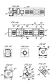
- Figures 3A and 3B are top and side views respectively of a unitary block forming the core of the accelerator assembly of Figure 2.
- Figures 3C and 3D are respective end views of the block of Figures 3A and 3B.
- Figures 3E, 3F and 3G are cross-sectional views taken through the block of Figures 3A and 3B along section lines C-C, F-F and D-D respectively.
- Figure 4A is a drawing from one side of the rf electrodes of the first stage of the rf accelerator assembly of Figure 2.
- Figure 4C illustrates one of the aperture plates forming the aperture of one of the electrodes of Figure 4A.
- Figure 4D is a cross-sectional view of the aperture plate of Figure 4C taken along line B-B.
- Figure 5A is a side view of the rf electrodes of the second stage of the rf accelerator assembly of Figure 2.
- Figure 5B is a cross-sectional view of one of the electrodes of Figure 5A taken along line G-G.
- Figures 6A and 6B are front and side views respectively of the entrance electrode of the first stage of the accelerator assembly of Figure 2.
- Figure 6C is a cross-sectional view of the entrance electrode of Figure 6A taken along line H-H.
- Figures 7A and 7B are side and end views respectively of the two coil assembly and resonant chamber for one of the stages of the accelerator assembly of Figure 2.
- Figures 8A and 8B are sectional and outside views of the coupler assembly for coupling rf energy to the resonant chamber of Figure 7.
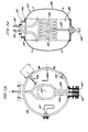
- Figure 9 is a schematic illustration of a squirt tube assembly used for water cooling the two coil assembly of Figure 7.
- Figures 10A and 10B are interior and cross-sectional views respectively of a pick up loop assembly used in the resonant chambers of Figure 7.
- Figures 11A and 11B are side and cross-sectional views respectively of an adjustable tuning capacitor used for tuning the resonant frequency of the resonant chambers of Figure 7.
- Figure 12 is a cross-sectional view taken along the beam direction of a magnetic quadrupole used for focusing the ion beam in the accelerator assembly of Figure 2.
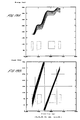
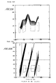
- Figure 14 is a graphical representation of the profiles at different times of an ion beam passing through the rf accelerator assembly illustrated in Figure 2, when the accelerator is energised.
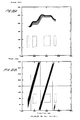
- Figure 15 is a graphical representation of the ion beam profile as in Figure 14, but with the accelerator in drift mode.
- Figure 16B is a graphical representation of the rf field wave form phases versus the position along the length of the three gap rf accelerator stage of the B + ions being accelerated by the stage, again when the applied field has maximum amplitude.
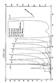
- Figure 23 is a graphical representation of beam current against output energy for a two stage three gap booster as represented in Figure 13 for different rf amplitudes.
- the beam exiting the rf accelerator assembly 10 then enters a beam scanning device 15 which is arranged to scan the ion beam to and fro in a direction 16 transverse to the beam direction.
- the scanning device 15 may be either electrostatic or electromagnetic. Electromagnetic scanning systems are preferred in applications especially for high current beams. A suitable electromagnetic scanning system is disclosed in U.S. Patent No. 5393984.
- the scanned beam then enters a process chamber 17 in which a semiconductor substrate 18 is held on a holder 19.
- the holder 19 is mounted on a mechanical scanning mechanism shown generally at 20 which can be actuated to reciprocate the wafer in a direction normal to the plane of the paper in Figure 1 and across the plane of the scanned beam.
- the combination of scanning of the beam and mechanical scanning of the wafer holder 19 allows the beam to scan over all parts of the wafer during an implant process. Processed wafers are removed from the holder 19 and passed out of the process chamber 17, and fresh wafers for processing are brought into the chamber 17 and mounted on the holder 19 one at a time, via a load lock 21, and using robot handling mechanisms which are not shown in this drawing for simplicity.
- the rf accelerator assembly 10 would normally be followed, along the beam direction, by an energy filter, illustrated generally in Figure 1 at 25.
- an energy filter illustrated generally in Figure 1 at 25.
- the use of such an energy filter following an rf accelerator in ion implanters is well known, see for example "Production of High Energy Ion Implanters Using Radio Frequency Acceleration" by Glavish et al, Nuclear Instruments and Methods in Physics Research, B21(1987) 264-269.
- the energy filter is used to limit the range of energies of ions from the accelerator which proceed to be implanted in the semiconductor substrate.
- the energy filter may take any known form such as an electrostatic inflector or an analyser magnet.
- Figure 2 illustrates a preferred embodiment of rf accelerator assembly such as may be incorporated as the assembly 10 in the ion implanter of Figure 1.
- the ion beam from the analyser magnet enters from the left in the direction of arrow 30 and passes through the accelerator generally along the line of axis 31.
- the accelerator is formed of two three-gap rf booster or accelerator cavities or stages in tandem and illustrated generally at 32 and 33. Whilst Figure 2 is generally a view of the accelerator assembly in elevation, parts of the outer walls of the vacuum chamber of the assembly have been broken away to reveal the location of the electrodes of the two acceleration stages represented by the cavities 32 and 33.
- the second accelerator stage 33 has a similar construction with entrance and exit electrodes 40 and 41 and intermediate rf electrodes 42 and 43, defining between them three accelerating gaps along the beam direction 30.
- Each of the electrodes 37 and 38 of the accelerator stage 32 is connected to a respective conductor 45 and 46 which leads out of the chamber enclosing the ion beam and into a resonant tank chamber 47. Inside the tank chamber 47, the conductors 45 and 46 are formed as coils and connected to ground.
- the electrodes 42 and 43 of the second accelerator stage 33 are similarly connected by conductors to coils within a similar resonant tank chamber 48.
- the tank circuit formed by the chamber 48 and the electrodes 42 and 43 is similarly arranged to have the same resonant frequency as the first resonant cavity 32.
- rf power is supplied to the resonant circuits formed by the cavities 32 and 33 with associated tank chambers 47 and 48, so that the rf electrodes 37, 38 and 42, 43 are energised with opposite polarity at the resonant frequency.
- bunches of ions from the ion beam along the axis 31 are then accelerated as they traverse the gaps between the electrodes in the two resonant cavities so as to emerge from the accelerator assembly with increased energy.
- Figure 2 also illustrates the location of magnetic quadrupoles along the beam axis 31 at 50, 51, 52 and 53.
- Magnetic quadrupoles are used, as is known to skilled workers in this field, to control expansion of an ion beam and bring the beam back to a required focus or waist.
- the magnetic quadrupoles 51 to 53 are used to control the expansion of the beam as it passes through the rf accelerator.
- the rf accelerator assembly of Figure 2 is constructed using a unitary block of metal as illustrated at 60 in Figures 3A and 3B.
- Figure 3A shows the basic unitary block 60 from above, corresponding to the top in Figure 2
- Figure 3B is a corresponding view from the side, corresponding to the elevational view of Figure 2.
- the block 60 is essentially divided along its length, corresponding to the axis 31, into five segments 61, 62, 63, 64 and 65. Segments 62 and 64 have essentially a square cross-section as illustrated in Figures 3E and 3F which are sectional views taken along the lines C-C and F-F of Figure 3B.
- the surfaces 80 comprise an end wall of the square section segment 64 immediately adjacent to the segment 65.
- each of the segments 62 and 64 are closed, in planes perpendicular to the axis 31, leaving only a central circular aperture between the respective segments 62, 64 and the adjacent segments 61, 63, 65.
- These circular apertures are illustrated at 81 in Figures 3E and 3F and at 82 in Figure 3G.
- the block 60 has webs 83, 84, 85 and 86 extending in radial planes parallel to the axis 31 midway between the corners of the adjacent square section segments 62, 64.
- the inner edges of the webs 83, 84, 85 and 86 are formed so that pairs of adjacent webs form a sealing surface 87 surrounding an aperture 88, between each pair of adjacent webs.
- These apertures 88 are used to receive the poles of magnetic quadrupoles 50, 51, 52 and 53 mounted on the block 60. The construction of these magnetic quadrupoles in relation to the block 60 will be described in more detail later herein.
- the yoke 100 includes a short bore 106 formed in an end of the yoke opposite to the end receiving the insulating post 91. This bore is provided to receive the conductor 46 ( Figure 2) extending from the tank chamber 47 to energise the electrode 38.
- the interior of the bore 106 is shaped to receive a compressible cylindrical element, which allows a good ohmic contact to be made at the required radio frequency between the yoke 100 of the electrode and the conductor 46 when received in the bore 106.
- the electrodes of Figure 4 are mounted through the aperture 71 ( Figure 3F) of block 60 so as to take up the position as shown in Figure 2, with the conductors 45, 46 from the associated tank chamber 47 received in the bores 106 of the electrodes.
- the conductive sleeves mounted in the bores 106 to ensure good rf ohmic contact are in the form of louvred compressible cylindrical strips and are known by the trade name "Multi-Lam”.
- the electrode assembly of Figure 5A is mounted in the block 60 through the aperture 74 of Figure 3E, and the conductors from the coil in the associated tank chamber 48 are received in bores 113 of the electrodes 42 and 43 in a manner similar to that for the electrode assembly of Figures 4A and 4B.
- the entrance electrode 35 of the first accelerator stage 32 is illustrated in Figures 6A, 6B and 6C.
- the electrode is mounted in a wall of the block 60 extending radially across the block, by means of mounting flange 115 secured by screws 116.
- the aperture of the electrode 35 is defined by a liner 117 which is replaceable by removing a clamping plate 118 secured to the flange by screws 119.
- the liner 117 may be made of graphite or aluminium and defines an aperture 120 through the electrode.
- the apertures of the electrodes used for the two stages 32 and 33 of the accelerator assembly are not circular.
- the aperture of the entrance electrode of the first stage 32 has a major dimension which is more than four times the minor dimension transverse to the beam path through the electrode.
- the apertures through the rf electrodes have a major dimension which is about three times the minor dimension of the aperture.
- Figure 7A is a cross-sectional view of the tank chamber 47
- Figure 7B is a corresponding cross-sectional view of the tank chamber of Figure 7A from one side.
- the tank chamber 47 comprises a central cylindrical part 130 and two opposed domed closure parts 131 and 132.
- the domed closures 31 and 32 are sealed to the ends of the cylindrical part 130 by vacuum seals 133 and 134. These vacuum seals extend circumferentially around the ends of the cylindrical part 130 and enable the domed closures 131 and 132 to be removed for servicing and inspection of the interior of the tank 47.
- the conductors 45 and 46 form respective coils 135 and 136 which are aligned so as to be coaxial on an axis 137, which is essentially coincident with the axis of the cylindrical part 130 of the tank chamber 47.
- the opposite ends of the coils 135 and 136 extend down at 138 and 139 to respective mounting points 140 and 141.
- the conductors 45 and 46 and coils 135 and 136 are formed of lengths of hollow copper pipe.
- the weight of the coils 135 and 136 is essentially supported by means of the lengths 138 and 139 from the connection points 140 and 141.
- the upper ends of the conductors 45 and 46 extend through an aperture in the cylindrical part 130 of the tank chamber 47 and through a corresponding aperture 70 in the block 60 of the accelerator assembly. As described previously, the ends of the conductors 45 and 46 are received in bores 106 in the electrodes 37 and 38 and form a sliding fit with these electrodes.
- the tank chamber 48 for the second accelerator stage 33 is constructed in a manner substantially identical to chamber 47 as illustrated in Figures 7A and 7B.
- Rf energy is coupled to the tank circuit by means of a coupling loop 150 (Figure 7B).
- This coupling loop is illustrated in greater detail in Figures 8A and 8B.
- the coupling loop comprises a single loop of conductor 151 having one end connected to ground at 152, and the other end connected to a vacuum feedthrough 153.
- the vacuum feedthrough 153 enables electrical connection to be made to the end of the loop 150 from outside the vacuum chamber.
- the loop as a whole is mounted on a disc 154 which is in turn mounted for rotary movement in a mounting plate 155 (see Figure 8B). Adjusting the rotational position of the disc 154 over a range of angles can provide corresponding adjustment of the angular position of the loop 151 relative to the tank chamber 47 and the coils 135 and 136. The angular position of the loop 151 may be adjusted in order to provide satisfactory coupling and impedance matching of rf energy into the tank circuit.
- An angle telltale 156 is provided on the external face of the mounting plate 155, so that the angular position of the loop 151 can be recorded for future reference.
- the level of rf current generated in the coils 135 and 136 in order to provide the required rf potential at the electrodes 37 and 38, is sufficient to generate substantial heating of the coils 135 and 136 and the remaining lengths of the conductors 45 and 46. Accordingly, the conductors are water cooled.
- Figure 9 illustrates part of a support point 140 showed mounting the fixed end 139 of coil 136.
- the conductor 46 is, as mentioned previously, made from a hollow copper pipe.
- a squirt tube 160 extends the length of the conductor 46 from the support point 140 up to close to the closed end 161 of the conductor 46.
- the squirt tube is formed of a double walled tube having an inner pipe 162 within an outer pipe 163. The space between the inner and outer pipes 162 and 163 is sealed at both ends and is then evacuated by a vacuum source connected to a connector 164.
- Cooling water introduced into the inner tube 162 at a connector 165 flows the length of the squirt tube 163 to emerge into the interior of the conductor 46 from a distal end 166 of the inner tube 162 close to the closed end 161 of the conductor. Cooling water then flows back down along the length of the conductor outside the squirt tube to flow to waste from the conductor via a connector 167.
- the inner supply tube 162 is substantially thermally insulated from the returning, heat-absorbing water flowing back down the conductor 46. As a result, the cooling water reaching the distal end 166 of the supply tube at the far end of the conductor 46 has not been substantially heated by the returning water.
- This construction ensures good cooling of the conductor 46 over its full length, and especially at the distal end adjacent the electrode connected to the conductor 46. It will be appreciated that the electrode itself may become relatively hot and the cooling arrangement for the conductor 46 ensures that the end of the conductor which is connected to the electrode is not also heated to an excessive temperature.
- One end of the loop 171 is connected to the chamber wall via a resistance 173 and the other end is connected to an rf feedthrough 174 so that the loop can be connected to an rf cable to supply a feedback signal to control equipment as will be described.
- a tuning capacitor 180 is also mounted on a wall of the tank chamber 47.
- FIGs 11A and 11B illustrate this tuning capacitor in greater detail.
- the capacitor comprises a capacitance plate 181 mounted transversely at the end of a rotary shaft 182.
- the rotary shaft 182 is mounted for rotation in a mounting flange 183 by which the capacitor can be mounted extending through an aperture in the wall of the tank chamber 47.
- a stepper motor 184 is mounted to the exterior of the mounting flange 183 and is coupled to drive an exterior end 185 of the rotary shaft 182 via gears 186 and 187.
- the shaft 182 passes through a rotary vacuum seal to allow the shaft to be rotated by the stepper motor 184 without ambient air leaking into the tank chamber 47.
- Rotation of the shaft 182 by the stepper motor 184 adjusts the proximity of the capacitor plate 181 to the coils 135 and 136 within the tank chamber 47, and thereby adjusts the resonant frequency of the resonant tank circuit.
- the tuning capacitor 180 is servo controlled by a control system which will be described later so as to maintain the resonant frequency of the tank circuit at the frequency of the rf signal energising the tank circuit via the coupling loop 150. It is important to keep the resonant frequency of the tank circuit precisely at the required frequency so as to maximise efficiency.
- FIG. 12 shows a sectional view of a quadrupole taken along the beam axis. Comparing Figure 12 with the sectional view illustrated in Figure 3G of part of the unitary mounting block 60, the webs 83, 84, 85 and 86 of the mounting block can be seen more clearly in Figure 12.
- the magnetic quadrupole is formed of four magnetic poles 190, 191, 192 and 193 which are arranged penetrating into the open area of the unitary block 60 defined by the apertures 82 ( Figures 3E and 3F). Each magnetic pole 190 to 192 is mounted in a respective one of the apertures 88 defined by the mounting surfaces 87 between the webs 83 to 86 of the unitary block 60.
- each magnetic pole has a flange 194 which is sealed against the respective support surface 87 and fastened in position by bolts 195.
- the magnetic poles 190 to 193 therefore effectively close the apertures 188 forming a vacuum seal between the flange 194 and the respective sealing surface 87.
- the magnetic poles 190 to 193 are effectively located within the vacuum chamber of the accelerator assembly so that the pole faces can be located as close as necessary to the axis of the beam, to maximise magnetic field strength, and also minimise stray magnetic fields.
- a respective magnetic core 196 is fixed to the outer face of each magnetic pole 190 to 193 and each core 196 is surrounded by a respective winding 197.
- These windings can be water cooled tubular conductive elements.
- Pairs of magnetic poles are then connected together by shunting yokes 198 and 199.
- one shunting yoke 198 links the cores 196 for magnetic poles 190 and 193
- the other shunting yoke 199 links the cores of the magnetic poles 191 and 192.
- the magnetic quadrupole structure described above enables the magnetic poles themselves to be located effectively within the vacuum chamber of the accelerator assembly, while the field windings of each pole are still exterior of the vacuum chamber in atmosphere. This is highly desirable to maximize the efficiency of the produced magnetic field, to facilitate cooling of the windings and also for improved accessibility for maintenance purposes.
- the pole pieces themselves are used effectively as closures of apertures in the vacuum chamber formed by the unitary block 60.
- FIG 13 is a schematic diagram of an rf accelerator assembly.
- the illustrated assembly comprises first and second rf accelerator cavities or stages 250 and 251 respectively arranged in tandem for changing the energy of a beam 252 of ions for implantation.
- the beam 252 is injected into the first rf accelerator cavity 250 at energy E (keV).
- Each cavity 250, 251 is a three gap cavity having grounded entrance and exit electrodes 253, 254 and 255, 256 respectively and a pair of intermediate rf electrodes 257, 258 and 259, 260 respectively.
- the electrodes of the first cavity 250 define a first gap 261, between entrance electrode 253 and first rf electrode 257, a second gap 262 between the two rf electrodes 257 and 258, and a third gap 263 between the second rf electrode 258 and the exit electrode 254.
- the cavity 251 has similar gaps 264, 265 and 266.
- the rf electrodes 257 and 258 of the first cavity 250 are connected to coils 268 and 269, and the rf electrodes 259 and 260 of the second cavity 251 are connected to coils 270 and 271.
- Each cavity 250, 251 incorporating the respective electrodes and coils provides a resonant tank designed to have a resonant frequency at or around a predetermined value f which is the intended operating frequency of the rf accelerator.
- the resonance of the cavities 250 and 251 can be fine tuned to match the desired operating frequency f by means of adjustable tuning capacitors 272 and 273.
- Rf energy is coupled to the respective cavities 250, 251 via coupling loops 274 and 275.
- Pick up loops 276 and 277 in the respective cavities provide an output on lines 278 and 279 providing a feedback signal representing the amplitude and phase of the rf voltage in the respective cavity.
- a pair of magnetic quadrupole lenses 280 and 281 are located in sequence between the cavities 250 and 251.
- An rf amplifier 282 amplifies an rf drive signal on a line 283 from an rf generator 284 and supplies the amplified rf signal to energise the coupling loop 274 in the first rf cavity 250.
- a second rf amplifier 285 amplifies an rf drive signal on a line 286 from a second rf generator 287, to supply an amplified rf signal to the coupling loop 275 of the second rf cavity 251.
- Each of the rf generators 284 and 287 include feedback control.
- the feedback control is effective to compare the feedback signal on the respective line 278 or 279 with amplitude demand signal and the fixed reference phase value to which the phase is locked.
- the amplitude demand and fixed phase value signals for the rf generator and feedback control 284 are provided on lines 291 and 293 respectively and the amplitude demand and fixed value phase signals for the generator and feedback control 287 are provided on lines 292 and 294 respectively.
- phase drift can result in bunches of charged particles passing through the accelerator not receiving the prescribed and preset acceleration.
- the feedback control in the rf generators 284 and 287 ensures that the phase of the field actually measured in the respective cavity is closely maintained at the respective fixed reference phase value.
- the fixed phase value signals on lines 293 and 294 are derived from a fixed phase preset unit 295, which produces fixed signals which cannot be adjusted either automatically or by operator intervention.
- the difference between the fixed phase value signals of the respective stages is either zero or 180°.
- Each of the rf generators 284 and 287 is typically a frequency synthesiser and the generators 284, 287 as well as the fixed phase preset unit 295 are all synchronised by clock pulses from a master clock 296.
- the resonant tank circuits 250 and 251 are provided to ensure that the required rf potential is applied to the rf electrodes in the respective cavity with minimum ohmic losses. Accordingly, it is very important that the resonance of the tank circuits is accurately at the fixed frequency f of the rf drive. Deviation of the tank circuit resonance from the drive frequency f requires the amplitude of the rf drive to be increased for the same rf voltage applied to the electrodes of the cavity. Also, if the resonance of the cavity drifts away from the frequency f, in the absence of feedback control, there would be a change in the phase of the rf voltage on the electrodes.
- the feedback control in the respective rf generator can provide compensation by changing the amplitude and phase of the rf drive on line 283 to maintain the amplitude represented by the feedback signal on line 278 at the demand value on line 291 and the phase of the feedback signal constant as required by the fixed value signal on line 293.
- the generator and feedback control 287 operates similarly to maintain correct amplitude and fixed phase in the cavity 251.
- the feedback control of the generators 284 and 287 also adjusts the variable capacitance 272 and 273 of the respective cavities by applying control signals on lines 297 and 298 respectively.
- feedback control of generator 284 may adjust the variable capacitor 272 of the cavity 250 to minimise the amplified error signal between the feedback phase on line 278 and the fixed phase signal on line 293.
- variable capacitor 272 is a mechanical device, as is described above and illustrated in Figures 11A and 11B, the response time of the variable capacitor 272 is relatively slow.
- the electronic feedback control of the rf drive signal is required to maintain accurate amplitude and fixed phase within the cavity in response to any fast changes in the feedback signal, such as can arise due to mechanical vibration of the cavity.
- the capacitance 272 is adjusted to compensate for slow changes in the resonance of the cavity, e.g. resulting from thermal expansion.
- the implant process as a whole is controlled by a micro processor based implant controller 290.
- the implant controller may control a number of operating parameters of the implanter but for the purposes of illustrating the present invention, the controller 290 is shown producing only the amplitude demand signals on lines 291 and 291 for the rf generator and feedback control units 284 and 287.
- the implant controller 290 may change the value of the demanded amplitude in response to various operator input controls, including specifically an operator requirement to set up the implanter for implanting ions of a different mass/charge ratio (m/e). This control is illustrated in Figure 13 by the input line 299.
- this flight time variation resulting from differences in mass-to-charge ratio for different ions is compensated for by keeping constant both the distance between the two cavities 250 and 251 and the phases of the rf voltages in the two cavities 250 and 251 and setting up the accelerator for the desired ion mass-to-charge ratio by altering the speed of the ions from the first cavity to the second.
- this is achieved by changing the amplitude demand signal on line 291 so that the rf field amplitude in the first cavity 250 is adjusted accordingly.
- a slight reduction in rf field amplitude in cavity 250 can slightly reduce the speed of the bunches of ions leaving the cavity, thereby increasing the flight time over distance 300, with the result that these bunches of ions arrive at the proper region in the rf voltage wave form in the gaps of cavity 251. Because of the substantial length of the distance 300, only a small variation in the speed (or energy) of ions from the first cavity can be sufficient to ensure a proper time of flight of these ions to the second cavity.
- the distance 300 is greater than the overall length between the entrance and exit electrodes, of the first cavity 250.
- the length 300 is about three times the length of the first cavity.
- the rf supplies to the two booster cavities of the illustrated accelerator arrangement can be fully controlled using only two control inputs, to set up the required rf amplitudes of the two cavities, for tuning the accelerator assembly for ions of different mass/charge ratio, as well as for providing a desired final ion energy. This can significantly simplify the setting up of the booster to deliver ions of different m/e values at required output energies.
- the overall length of the rf accelerator assembly from the entrance electrode of the first cavity to the exit electrode of the second cavity is L.
- the electrodes forming the cavities of the assembly have apertures with a largest transverse dimension which is not less than a distance D. It will be understood that this largest transverse dimension would be the major dimension of the slit-shaped electrode apertures, as have been described above with respect to Figures 4, 5 and 6.
- L/D is less than about 25
- an excellent combination of performance parameters is obtained.
- the overall length L of the accelerator is still rather low, which reduces the footprint of the tool when installed in a lab.
- the transverse dimension D of the apertures through the accelerator, in at least one axial plane is relatively large, which improves the acceptance of the accelerator allowing larger beam currents, especially during drift mode when the accelerator assembly is inactive, for implants at energies F and below.
- Our preferred design has a value of L/D of about 18.
- the implanter may comprise an ion beam generator for generating a beam of ions to be implanted, in which said ions are at a first energy, and a radio frequency linear accelerator assembly arranged when energised for accelerating ions of said beam to a second energy, said assembly comprising electrodes defining a series of gaps for changing the energy of ions of said beam, said electrodes having apertures through which the ions pass, wherein all the electrodes of said assembly are contained in a length L and the apertures of the electrodes have respective largest dimensions transverse to the beam which are not less than D, where L/D is less than 25.
- each of said booster stages comprising entrance and exit electrodes and at least one intermediate rf electrode defining a series of gaps for changing the energy of the ions of said beam, and an adjacent pair of magnetic quadrupoles located between said first and second booster stages.
- the performance of the slit shaped electrodes used in the accelerator assembly can be visualised from Figures 14 and 15 which show the profile of an ion beam passing through the elements of the accelerator.
- the upper part of each of Figures 14 and 15 shows the beam profile in an X direction transverse to the beam axis, and the lower part of the Figure shows the beam profile in the orthogonal Y direction transverse to the beam axis.
- the Y direction is the direction of the long dimension of the slit apertures of the electrodes.
- electrodes 310 of the first accelerator cavity and electrodes 311 of the second accelerator cavity are shown spaced relatively close to the axis 312 of the beam in the X direction (top part of the drawings) and relatively further away from the axis in the Y direction (bottom part of the drawings).
- the beam direction is from left to right.
- the beam injected into the accelerator has similar dimensions in both X and Y directions.
- a first magnetic quadrupole focuses the beam in the X direction, and tends to defocus the beam in the Y direction.
- the beam is confined in the X direction to approximately 6 mm from the beam axis, whereas the beam extends in the Y direction to over 15 mm from the axis 312.
- the effect of the two magnetic quadrupoles 314 and 315 between the two cavities of the accelerator is illustrated.
- the first quadrupole 314 brings the beam back towards a focus in the X direction, and the second quadrupole 315 refocuses the beam in the Y direction.
- the simulation represented in Figure 14 assumes an injected beam of doubly charged phosphorous at 200 keV and a final beam energy after acceleration of about 850 keV.
- the beam emitted by the accelerator assembly is assumed to contain ions arriving at the first accelerating cavity over ⁇ 50° of phase of the rf excitation voltage applied to the first cavity.
- the effect of the accelerator assembly on ions of different injection phases is represented by the different profile lines in the drawing.
- Figure 15 represents the profile of the beam passing through the accelerator assembly in drift mode, that is when the electrodes of the accelerator assembly are not energised, so that no acceleration of the beam takes place.
- the injected beam is again P ++ at 200 keV.
- the beam profile extends further in the Y direction than the X direction.
- the X direction in Figures 14 and 15, that is the narrow dimension of the slit apertures of the electrodes, should be aligned with the dispersion plane of the analyser magnet 12 which is located upstream of the rf accelerator assembly, as illustrated in Figure 1.
- the magnet 12 functions to bring ions of the desired m/e to a substantial focus in the X direction. Normally a mass selection slit is located at this focus to allow only the required ions to continue in the beam for implantation.
- the focal point of the mass analyser magnet is within the first three gap booster stage of the rf accelerator.
- the magnet 12 is also effective to bring the beam to a waist in the Y direction in the vicinity of the first magnetic quadrupole 313 ( Figures 14 and 15) in front of the entrance electrode of the first booster stage.
- This magnetic quadrupole 313 is then energised so as to shift the effective waist in the beam in the Y direction to the location along the beam of the second magnetic quadrupole 314, immediately after the first booster stage.
- the first quadrupole 313 is energised to provide focusing in the X direction and defocusing in the Y direction.
- the ion beam entering the analysing magnet 12 from the ion source 11 is usually ribbon shaped having a narrow transverse dimension in the dispersion plane of the magnet.
- the beam of ions of required m/e leaving the magnet 12 can be brought to a relatively tight focus in the X direction, but to a wider waist in the Y direction, of dimensions dependant on the ion species and the set up or "tuning" of the ion source.
- the Y-defocusing, X-focusing effect of the first magnetic quadrupole 313 produces a relatively small shift (to the left in Figure 14) in the position of the X-focus of the beam, which is close to the first and second electrodes of the first booster stage. In this way the beam is compressed in the X direction to pass through the narrow dimensions of the slit apertures of the electrodes.
- the beam ions pass through the first booster stage, ions near the edge of the beam, in the X direction, experience focusing effects due to curvature of the electric field near the aperture edges of the electrodes.
- Ions passing through the booster at different times relative to the phase of the rf field are focused/defocused by differing amounts, which is represented in Figure 14 by the separating of the beam profile in the X direction into several lines. This modest effect in the first booster stage becomes more dramatic in the second booster stage and adds to the difficulty in controlling the beam through the accelerator and subsequently.
- the first magnetic quadrupole moves the Y-waist in the beam to the location of the second quadrupole 314.
- This second quadrupole is required to bring the beam back to a focus in the X direction at the following third quadrupole 315.
- the beam has a Y waist at the second quadrupole 314, the Y-defocusing effect is reduced, and the beam can then be brought back towards a Y-waist by the third quadrupole 315 without excessive X defocusing.
- a fourth magnetic quadrupole may then be provided after the exit electrode of the second booster stage to provide some X-refocusing, which is generally required to match the ion optical characteristics of the energy filter 25.
- the aperture of the electrodes of the first booster stage function as the mass selection slit of the implanter (assuming there is no velocity variation in the ions passing through the analyser magnet), since ions of other m/e in the beam will not enter and pass through the booster without hitting an electrode.
- a baffle plate may be located just in front of the entrance electrode of the first booster stage to absorb the greater part of the non-selected ions from the beam, so as to avoid damaging or overheating the entrance electrode.
- FIG. 16B shows ions entering the first gap of the accelerator stage at points in the rf waveform with phase angles ranging from about 90° to about 150°.
- the first ions represented in Figure 16B to enter the gap at 90° phase angle cross the centre of the gap at about 135° phase angle, represented by the lowermost line in Figure 16B.
- the latest ions to enter the gap at about 160° phase angle cross the centre of the gap at a phase angle of just over 180°.
- the maximum acceleration in the first gap of the accelerator stage occurs at the phase angle of 180°.
- ions crossing the centre of the gap at around 180° phase angle should experience the greatest increase in energy on crossing the gap. Ions crossing the centre of the gap at smaller phase angles should experience lesser increases in energy.
- the ions then traverse the third gap crossing the centre of the third gap at phase angles between about 170° and 200°.
- the phase of maximum acceleration in the third gap is 180°.
- the energy increment provided by the third gap is shown in Figure 16A at 402.
- the percentage energy dispersion of the final beam is important.
- finally implanted ions should have energies which fall within a certain percentage of the target energy, say ⁇ 5%.
- the final energy of ions leaving the accelerator stage is about 300 keV ⁇ 15 keV. This was achieved from ions injected into the accelerator stage having a range of phases of about 60°. It can be seen, therefore, that adequate energy dispersion performance is obtained over an input phase range which will capture nearly 17% of the ions in an unbunched injected beam. This level of performance can be obtained with a three gap rf cavity designed so that ions cross the first gap when the field is rising (as defined above), and cross the third gap when the field is falling.
- the ion implanter may comprise an ion beam generator for generating a beam of ions to be implanted, in which said ions are at an injection energy E, a three gap linear accelerator stage into which said beam of ions is directed at said injection energy, said stage being arranged when energised for accelerating ions of said beam to a second energy, said stage comprising an entrance electrode held at a fixed potential, an exit electrode held at a fixed potential, first and second radio frequency electrodes located in series between said entrance and exit electrodes, and a radio frequency generator to apply, respectively to said first and second radio frequency electrodes, radio frequency voltages of opposite polarity and having a maximum amplitude V relative to ground, said ion beam generator being arranged to control said injection energy E so that E ⁇ 2V.e,
- the three gap accelerator stage is optimised for BE ions (and nearly optimised for P ++ ions)
- an arrangement is provided in which a relatively high proportion of injected ions can be accelerated to within a small percentage of the target energy.
- the output energy of the accelerator stage can easily be varied by adjusting the applied rf amplitude, while maintaining efficiency in terms of the proportion of injected ions delivered at or close to the desired output energy. This level of flexibility is highly desirable in an ion implanter and results from the particular features detailed above.
- FIG. 23 This is a plot, in arbitrary units, of energy along the x-axis against beam current along the y-axis, of the beam ions delivered by the rf accelerator assembly described above, with two three gap accelerating cavities.
- Plot g represents the delivered beam at the injection energy of 70 keV with the rf accelerator in drift mode.
- Plots a to e represent the delivered beam with the second booster stage inactive and at five incremental settings of the amplitude of the rf voltage applied to the first booster stage.
- both the beam current and the beam energy spread is remarkably constant for increasing output energies.
- the flight time of B + ions should be reduced by only 12 nsec to arrive correctly at the second cavity, implying an increment to the energy of the B + ions leaving the first accelerator stage of about 12%.
- the flight time along the drift length 300 would be 184 nsec, implying a required reduction in the energy of the B ++ ions of about 16% to arrive correctly.
- the rf accelerator assembly described above would normally incorporate a buncher structure located upstream of the first three gap accelerating stage or cavity.
- the buncher would be designed to capture up to 30% (or more) of the unbunched beam ions and produce a controlled energy spread in the captured ions so that they become physically bunched on entry into the first accelerating stage. In order to maximise the proportion of beam ions captured, a buncher does not give any overall energy increment to the bunched ions.
- a suitable buncher is a two gap structure energised at the same rf frequency as the accelerator stages and with a phase locked to a fixed reference phase.
Landscapes
- Chemical & Material Sciences (AREA)
- Analytical Chemistry (AREA)
- Particle Accelerators (AREA)
- Electron Sources, Ion Sources (AREA)
- Physical Vapour Deposition (AREA)
Abstract
Description
| overall length (L) of accelerator assembly from entrance electrode of first cavity to exit electrode of second cavity | 587 mm |
| transverse dimensions of aperture of entrance electrode of first cavity | 46 x 10 mm |
| transverse dimensions of aperture of first rf electrode of first cavity | 34 x 10 mm |
| transverse dimensions of aperture of second rf electrode of first cavity | 34 x 12 mm |
| transverse dimensions of aperture of exit electrode of first cavity and both entrance and exit electrodes of second cavity | 46 x 12 mm |
| transverse dimensions of aperture of first and second rf electrodes of second cavity | 34 x 12 mm |
| smallest slit length of all electrode apertures in the assembly (D) | 34 mm |
| gap between entrance electrode and first rf electrode of first cavity | 14 mm |
| length along beam axis of first rf electrode of the first cavity | 16 mm |
| gap between first and second electrodes of first cavity | 32 mm |
| length along beam axis of second rf electrode of first cavity | 26 mm |
| gap between second rf electrode and exit electrode of first cavity | 16 mm |
| drift distance between exit electrode of first cavity and entrance electrode of second cavity | 349 mm |
| gap between entrance electrode and first rf electrode of second cavity | 16 mm |
| length along beam axis of first rf electrode of second cavity | 30 mm |
| gap between first and second rf electrodes of second cavity | 32 mm |
| length along beam axis of second rf electrode of second cavity | 40 mm |
| gap between second rf electrode and exit electrode of second cavity | 16 mm |
Nevertheless, the ions cross the centre of the middle gap around 360/0° to receive maximum energy boost from this gap and then cross the centre line of a third gap mostly at phase angles below 180°. Thus, the ions cross the third gap when the field is rising from maximum deceleration to maximum acceleration. However, because of the reversal of phase spread produced by the first gap, ions crossing the first gap early now cross the third gap relatively late and receive additional energy. Thus, in the case of B++ ions, crossing the third gap before 180° is effective to remove the energy dispersion introduced by the first gap.
Claims (34)
- An ion implanter comprising an ion beam generator for generating a beam of ions to be implanted in which said ions are at a first energy, and a radio frequency linear accelerator assembly arranged when energised for accelerating ions of said beam to a second energy, said assembly comprising electrodes defining a series of gaps for changing the energy of ions of said beam, said electrodes having apertures through which the ions pass, wherein the apertures of the electrodes defining the gaps of the accelerator assembly have respective first dimensions in a first orthogonal direction transverse to the beam direction and respective second dimensions in a second orthogonal direction transverse to the beam direction, said first dimension of the aperture of at least a first electrode defining a first gap of said series being smaller than said second dimension of said first electrode aperture.
- An ion implanter as claimed in Claim 1, wherein said first dimension of the aperture of the second electrode defining a first gap of the accelerator assembly is smaller than said second dimension of said second electrode aperture.
- An ion implanter as claimed in Claim 1 or Claim 2, wherein said first dimension of the apertures of each of the electrodes defining at least first and second gaps of the accelerator assembly is smaller than said second dimension of the aperture of the respective electrode.
- An ion implanter as claimed in Claim 1, wherein at least a sequential set of said electrodes each has said first aperture dimension smaller than said second aperture dimension, and there is at least one increment in the respective first dimensions along said sequential set of electrodes in the beam direction.
- An ion implanter as claimed in any one of Claims 1 to 4, wherein said ion beam generator includes a mass analyser magnet having a dispersion plane aligned with said first orthogonal direction.
- An ion implanter as claimed in Claim 5, wherein said mass analyser magnet is arranged to bring the desired ions to be implanted in said beam to a substantial focus in said first orthogonal direction at a location along the beam which is not upstream (towards the ion source) relative to the first electrode.
- An ion implanter as claimed in Claim 6, wherein said accelerator assembly comprises at least first and second rf booster stages in tandem along the beam direction, each booster stage comprising entrance and exit electrodes and at least one intermediate rf electrode together constituting said electrodes defining said gaps, the entrance electrode of the first booster stage being said first electrode, and the implanter further comprises a first magnetic quadrupole upstream of said first booster stage, a first power supply connected to energise said first quadrupole for focusing beam ions in said first orthogonal direction and defocusing said ions in said second orthogonal direction, a second magnetic quadrupole downstream of said first booster stage, and a second power supply connected to energise said second quadrupole for focusing beam ions in said first orthogonal direction and defocusing said ions in said second orthogonal direction.
- An ion implanter as claimed in Claim 7 and including a third magnetic quadrupole between said second quadrupole and said second booster stage and a third power supply connected to energise said third quadrupole for focusing beam ions in said second orthogonal direction and defocusing said ions in said first orthogonal direction.
- An ion implanter comprising an ion beam generator for generating a beam of ions to be implanted, in which said ions have a predetermined mass/charge ratio and are at an injection energy E, a three gap linear accelerator stage into which said beam of ions is directed at said injection energy, said stage being arranged when energised for accelerating ions of said beam to a second energy, said stage comprising an entrance electrode held at a fixed potential and an exit electrode held at a fixed potential, first and second radio frequency electrodes located in series between said entrance and exit electrodes, and a radio frequency generator to apply radio frequency voltages of opposite polarity and a predetermined frequency f respectively to said first and second electrodes, said entrance electrode and said first radio frequency electrode defining a first accelerating gap, said first and second radio frequency electrodes defining a second accelerating gap having a centre point at a first predetermined spacing d1 from the centre point of the first gap, and said second radio frequency electrode and said exit electrode defining a third accelerating gap having a centre point at a second predetermined spacing d2 from said centre point of the second gap, wherein the injection energy E, the frequency f, and the gap spacings d1 and d2 are selected such that at amplitudes of the radio frequency energy below the maximum amplitude at which breakdown occurs across any of said gaps, injected ions of said beam which cross the first gap when the radio frequency field across the first gap is rising from a maximum deceleration field to a maximum acceleration field, then cross the second gap during the maximum acceleration field across the second gap and cross the third gap when the field across the third gap is falling from a maximum acceleration field to a maximum deceleration field.
- An ion implanter comprising an ion beam generator for generating a beam of ions to be implanted in which said ions are at a first energy, and a radio frequency linear accelerator assembly arranged when energised for accelerating ions of said beam to a second energy, said assembly comprising a housing, electrodes mounted in the housing, said electrodes defining a series of gaps for changing the energy of ions of said beam, said electrodes having apertures through which the ions pass, at least one inductive coil electrically connected to at least one of said electrodes for energising said at least one electrode at a radio frequency potential, and an electrically conductive enclosure around said coil, said coil, said at least one electrode, said housing and said conductive enclosure together constituting a radio frequency tank circuit having a predetermined resonant frequency, said coil comprising a self supporting rigid electrical conductor having at least first and second connecting arms, said linear accelerator assembly including a coil mounting fixture on said electrically conductive enclosure arranged to receive said first connecting arm for electrical connection to said enclosure and for supporting said coil at a desired location within said enclosure, and an electrically insulating mount locating said at least one electrode within said housing, said second connection arm extending from said enclosure into said housing to make radio frequency connection to said at least one electrode, said at least one electrode having a connection fitting adapted to provide a sliding fit connection with said second connecting arm, whereby thermal expansion and contraction of said coil is accommodated by sliding movement of said second arm in said fitting.
- An ion implanter as claimed in Claim 10, wherein said electrically insulating mount and said connection fitting are on opposite sides of said at least one electrode, in a direction transverse to the beam direction.
- An ion implanter as claimed in Claim 11, wherein said electrically insulating mount comprises a mounting rod extending from said housing and said mounting rod and said second connection arm of said coil are substantially co-axial on opposite sides of said at least one electrode.
- An ion implanter comprising an ion beam generator for generating a beam of ions to be implanted in which said ions are at a first energy, and a radio frequency linear accelerator assembly arranged when energised for accelerating ions of said beam to a second energy, said assembly comprising a housing, electrodes mounted in the housing, said electrodes defining a series of gaps for changing the energy of ions of said beam, said electrodes having apertures through which the ions pass, at least one inductive coil electrically connected to at least one of said electrodes for energising said at least one electrode at a radio frequency potential, and an electrically conductive enclosure around said coil, said coil, said at least one electrode, said housing and said conductive enclosure together constituting a radio frequency tank circuit having a predetermined resonant frequency, said coil comprising a tubular electrical conductor having an open end and a closed end, said linear accelerator assembly including a connecting fixture on said electrically conductive enclosure to receive said open end to enable access to said open end from outside said enclosure, and a double walled cooling tube extending in said tubular conductor from said open end to a position proximate said closed end, said cooling tube comprising an inner pipe which is open at said proximate position to the interior of said tubular conductor and an outer pipe which is closed at said proximate position, said inner and outer pipes providing a space between them along the length of said cooling tube, a source of vacuum connected to said outer pipe to evacuate said space between said inner and outer pipes, and a source of cooling fluid connected to one of said inner pipe and said open end of said tubular conductor to provide a flow of said cooling fluid along said tubular conductor.
- An ion implanter comprising an ion beam generator for generating a beam of ions to be implanted in which said ions are at a first energy, and a radio frequency linear accelerator assembly arranged when energised for accelerating ions of said beam to a second energy, said assembly comprising electrodes defining a series of gaps for changing the energy of ions of said beam, said electrodes having apertures through which the ions pass, and at least one magnetic quadrupole located along the beam adjacent at least one of said electrodes for controlling beam divergence, said assembly further comprising a unitary block providing a vacuum housing for the assembly, said unitary block having a through channel for said beam to pass through, a plurality of electrode mounting points for mounting said electrodes to define a plurality of said gaps along the length of said through channel, and at least one magnetic quadrupole mounting point for mounting said magnetic quadrupole.
- An ion implanter as claimed in Claim 14, wherein said magnetic quadrupole mounting point of said block comprises a generally tubular portion of said block co-axial with said through channel, four apertures spaced uniformly about the circumference of said tubular portion, and a respective sealing flange provided around each of said apertures, and wherein said magnetic quadrupole has a respective pole piece mounted at each of said sealing flanges so as to extend through the respective aperture into said tubular portion, said sealing flanges providing vacuum seals between the pole pieces and said block.
- An ion implanter as claimed in Claim 15, wherein the magnetic quadrupole has a respective pole winding for each pole piece, said pole winding being located outside said sealing flanges so as to be in atmosphere when the vacuum housing is evacuated.
- A method of implanting ions into a target substrate comprising the steps of generating a beam of the ions at a first energy, and changing the energy of ions in the beam to a second energy using a radio frequency (rf) linear accelerator assembly having at least first and second booster stages in tandem along the beam direction, each of the booster stages comprising entrance and exit electrodes and at least one intermediate rf electrode defining a series of gaps for changing the energy of ions of said beam, the exit electrode of the first booster stage and the entrance electrode of the second booster stage defining between them a drift distance between the stages over which beam ions are not subject to rf fields, wherein the speed of bunches of ions from the first booster stage over said drift distance is adjusted to adjust the flight time of the ion bunches to the second booster stage.
- A method of implanting ions as claimed in Claim 17, wherein said speed is adjusted by adjusting the amplitude of the rf fields in the first booster stage.
- A method of implanting ions as claimed in Claim 17 or Claim 18, wherein the linear accelerator assembly is changed from being set up for accelerating beam ions of a first mass/charge ratio to being set up for accelerating beam ions of a second mass/charge ratio by adjusting the speed over said drift distance of said ions of second mass/charge ratio while maintaining the phase of rf fields in said first and second booster stages locked to fixed values.
- An ion implanter comprising an ion beam generator for generating a beam of ions to be implanted, in which said ions are at a first energy, and a radio frequency (rf) linear accelerator assembly arranged, when energised, for accelerating ions of said beam to a second energy, said assembly comprising at least first and second rf booster stages in tandem along the beam direction, each of said booster stages comprising entrance and exit electrodes and at least one intermediate rf electrode defining a series of gaps for changing the energy of ions of said beam, the exit electrode of the first booster stage and the entrance electrode of the second booster stage defining between them a drift distance between the stages over which beam ions are not subject to rf fields, and a controller arranged to adjust the speed of said ion bunches over said drift distance to adjust the flight time of the ion bunches to the second booster stage.
- An ion implanter as claimed in Claim 20, wherein said drift distance is greater than the length of the first booster stage between the entrance and exit electrodes thereof.
- An ion implanter as claimed in any one of Claims 21 to 22, wherein said drift distance is about twice said length.
- An ion implanter as claimed in any one of Claims 20 to 22, wherein said controller is arranged to adjust said speed of said ion bunches by adjusting the amplitude of the rf fields in the first booster stage.
- An ion implanter comprising an ion beam generator for generating a beam of ions to be implanted, in which said ions are at a first energy, and a radio frequency (rf) linear accelerator assembly arranged, when energised, for accelerating ions of said beam to a second energy, said assembly comprising at least first and second resonant cavities in tandem along the beam direction, said cavities comprising electrodes defining a series of gaps for changing the energy of ions of said beam, a rf power supply to provide a first supply of rf energy at a first frequency to said first cavity, said first cavity being resonant at said first frequency, whereby to produce corresponding first rf accelerating fields between electrode gaps in said first cavity, said first fields having a phase and an amplitude, said rf power supply providing a second supply of rf energy at a second frequency, which is the same as or a harmonic of said first frequency, to said second cavity, said second cavity being resonant at said second frequency, whereby to produce corresponding second rf accelerating fields between electrode gaps in said second cavity, said second fields having a phase and an amplitude, and a controller arranged to adjust the flight time of the bunches of ions from the first cavity to the second cavity by adjusting the amplitude of said first fields in said first cavity while maintaining locked to fixed values the phases of said first and second fields.
- An ion implanter comprising an ion beam generator for generating a beam of ions to be implanted in which said ions are at a first energy, and a radio frequency linear accelerator assembly arranged when energised for accelerating ions of said beam to a second energy, said assembly comprising first and second rf booster stages in tandem along the beam direction, each of said booster stages comprising entrance and exit electrodes and at least one intermediate rf electrode defining a series of gaps for changing the energy of the ions of said beam, and an adjacent pair of magnetic quadrupoles located between said first and second booster stages, said electrodes having apertures through which the ions pass, all the electrodes of said first and second booster stages being contained in a length L and the apertures of the electrodes having respective largest dimensions transverse to the beam which are not less than D, where L/D is less than 25.
- A method of operating a three gap radio frequency (rf) accelerator stage for accelerating ions of a selected mass/charge ratio (m/e) from an injection energy E to a second energy, comprising providing the accelerator stage to be energisable with an rf voltage having a maximum amplitude A without breakdown occurring, applying an rf voltage of frequency f to generate corresponding rf accelerating fields in the accelerator stage, and selecting the injection energy E, the frequency f and the spacings d1 and d2 between the centres of the first and second gaps and between the second and third gaps respectively of the accelerator stage, such that, with the rf voltage amplitude not greater than A, said ions cross the first gap when the radio frequency field across the first gap is rising from a maximum deceleration field to a maximum acceleration field, then cross the second gap during the maximum acceleration field across the second gap and cross the third gap when the field across the third gap is falling from a maximum acceleration field to a maximum deceleration field.
- A method as claimed in Claim 26, wherein the amplitude of the rf voltage is adjusted to values less than A to reduce the second energy.
- Apparatus for generating a beam of ions of a selected mass/charge ratio and a desired energy for implantation in a substrate, the apparatus comprising an ion source providing a beam of ions at a first energy, an analyser magnet which receives said beam of ions at said first energy and spacially resolves ions of said beam at a resolving plane transverse to the beam direction, in accordance with the momentum of said ions, a first three gap linear accelerator cavity having an entrance electrode located adjacent said resolving plane so that ions of selected momentum from said beam are injected into said first cavity at said first energy, a second three gap linear accelerator cavity to receive ions from said first cavity, and a pair of magnetic quadrupoles between said first and second cavities for controlling spreading of ions passing through said cavities.
- Apparatus as claimed in Claim 28 and including first and second controllable rf power supplies for applying rf power to said first and second cavities respectively, and an ion energy controller having a first control mode in which at least said first rf power supply is controlled to energise said first cavity to increase the energy of selected ions to a second energy above said first energy and having a second control mode in which both said first and second rf power supplies are controlled to supply no rf power to said first and second cavities so that selected ions pass through said cavities at said first energy.
- Apparatus as claimed in Claim 29 including respective controllable energising current supplies to said magnetic quadrupoles, and wherein said controller is operative in each of said first and second modes to control said current supplies for enhancing the current of said selected ions energising from said second cavity in the respective mode.
- An ion implanter comprising an ion beam generator for generating a beam of ions to be implanted in which said ions are at a first energy, and a radio frequency linear accelerator assembly arranged when energised for accelerating ions of said beam to a second energy, said assembly comprising a housing, electrodes mounted in the housing, said electrodes defining a series of gaps for changing the energy of ions of said beam, said electrodes having apertures through which the ions pass, at least one inductive coil electrically connected to at least one of said electrodes for energising said at least one electrode at a radio frequency potential, an electrically conductive enclosure around said coil, said coil, said at least one electrode, said housing and said conductive enclosure together constituting a radio frequency tank circuit having a predetermined resonant frequency, a coupling loop mounted in said enclosure, and a feed through permitting supply of rf power to said coupling loop for coupling said power to said resonant tank circuit, said coupling loop being mounted for rotary adjustment in said enclosure for changing the coupling efficiency of rf power to the tank circuit.
- An ion implanter as claimed in Claim 31, wherein said enclosure has a wall, a circular mounting plate having an axis and located in the wall for rotary adjustment about said axis, said coupling loop being mounted on said plate for rotary adjustment therewith, said feed through extending from said loop through said mounting plate.
- An ion implanter as claimed in Claim 32, wherein said wall has a circular sealing surface extending outwardly relative to the enclosure, and said circular mounting plate seals against said sealing surface.
- An ion implanter as claimed in Caim 32 or Claim 33, including an adjustment scale on one of said circular mounting plate and adjacent surfaces of said enclosure wall, and a marker on the other thereof, said scale and said marker being visible from outside said enclosure for indicating a desired angular position of said coupling loop.
Applications Claiming Priority (2)
| Application Number | Priority Date | Filing Date | Title |
|---|---|---|---|
| US321731 | 1989-03-10 | ||
| US09/321,731 US6423976B1 (en) | 1999-05-28 | 1999-05-28 | Ion implanter and a method of implanting ions |
Publications (2)
| Publication Number | Publication Date |
|---|---|
| EP1056113A2 true EP1056113A2 (en) | 2000-11-29 |
| EP1056113A3 EP1056113A3 (en) | 2007-02-28 |
Family
ID=23251785
Family Applications (1)
| Application Number | Title | Priority Date | Filing Date |
|---|---|---|---|
| EP00303209A Withdrawn EP1056113A3 (en) | 1999-05-28 | 2000-04-17 | Ion implanter and a method of implanting ions |
Country Status (3)
| Country | Link |
|---|---|
| US (1) | US6423976B1 (en) |
| EP (1) | EP1056113A3 (en) |
| JP (1) | JP4986317B2 (en) |
Cited By (11)
| Publication number | Priority date | Publication date | Assignee | Title |
|---|---|---|---|---|
| WO2002054443A3 (en) * | 2000-12-28 | 2002-11-21 | Axcelis Tech Inc | Ion accelaration method and apparatus in an ion implantation system |
| WO2003019612A1 (en) * | 2001-08-23 | 2003-03-06 | Axcelis Technologies, Inc. | Split double gap buncher and method for ion bunching in an ion implantation system |
| WO2003019613A1 (en) * | 2001-08-23 | 2003-03-06 | Axcelis Technologies, Inc. | Method and apparatus for improved ion bunching in an ion implantation system |
| GB2380601A (en) * | 2001-10-05 | 2003-04-09 | Applied Materials Inc | Radio frequency linear accelerator |
| US6878946B2 (en) | 2002-09-30 | 2005-04-12 | Applied Materials, Inc. | Indirectly heated button cathode for an ion source |
| WO2022060470A1 (en) | 2020-09-17 | 2022-03-24 | Applied Materials, Inc. | System, apparatus and method for multi-frequency resonator operation in linear accelerator |
| WO2022164525A1 (en) * | 2021-01-29 | 2022-08-04 | Applied Materials, Inc. | Rf quadrupole particle accelerator |
| WO2023069229A1 (en) * | 2021-10-20 | 2023-04-27 | Applied Materials, Inc. | Linear accelerator coil including multiple fluid channels |
| CN116031126A (en) * | 2022-12-27 | 2023-04-28 | 北京烁科中科信电子装备有限公司 | A beamforming resonator device for a high-energy ion implanter |
| US12302487B2 (en) | 2022-09-29 | 2025-05-13 | Applied Materials, Inc. | Particle accelerator having novel electrode configuration for quadrupole focusing |
| EP4241539A4 (en) * | 2020-11-06 | 2025-06-11 | Applied Materials, Inc. | SYSTEM, APPARATUS AND METHOD FOR FORMING A VARIABLE LENGTH ELECTRODE IN A LINEAR ACCELERATOR |
Families Citing this family (42)
| Publication number | Priority date | Publication date | Assignee | Title |
|---|---|---|---|---|
| KR100363333B1 (en) * | 2000-12-04 | 2002-12-05 | 삼성전자 주식회사 | Apparatus for monitoring parameters of a high voltage chamber of a semiconductor wafe processing system |
| WO2004036384A2 (en) * | 2002-10-18 | 2004-04-29 | Intellocity Usa, Inc. | Ichoose video advertising |
| DE10317894B9 (en) * | 2003-04-17 | 2007-03-22 | Leo Elektronenmikroskopie Gmbh | Charged particle focusing system, electron microscopy system and electron microscopy method |
| US20060105182A1 (en) * | 2004-11-16 | 2006-05-18 | Applied Materials, Inc. | Erosion resistant textured chamber surface |
| US7221553B2 (en) * | 2003-04-22 | 2007-05-22 | Applied Materials, Inc. | Substrate support having heat transfer system |
| US7145157B2 (en) * | 2003-09-11 | 2006-12-05 | Applied Materials, Inc. | Kinematic ion implanter electrode mounting |
| US7087913B2 (en) * | 2003-10-17 | 2006-08-08 | Applied Materials, Inc. | Ion implanter electrodes |
| US20080073559A1 (en) * | 2003-12-12 | 2008-03-27 | Horsky Thomas N | Controlling the flow of vapors sublimated from solids |
| US7820981B2 (en) * | 2003-12-12 | 2010-10-26 | Semequip, Inc. | Method and apparatus for extending equipment uptime in ion implantation |
| US7015661B2 (en) * | 2004-03-15 | 2006-03-21 | Steris Inc. | Method and apparatus for accelerating charged particles |
| KR100538813B1 (en) * | 2004-07-31 | 2005-12-23 | 주식회사 하이닉스반도체 | Implanter for uniformity of transistor parameter and method for implantation using the same |
| US7598505B2 (en) * | 2005-03-08 | 2009-10-06 | Axcelis Technologies, Inc. | Multichannel ion gun |
| CN101248505B (en) | 2005-07-08 | 2010-12-15 | 耐克斯金思美控股公司 | Apparatus and methods for the manufacture of controlled particle beams |
| US7402821B2 (en) * | 2006-01-18 | 2008-07-22 | Axcelis Technologies, Inc. | Application of digital frequency and phase synthesis for control of electrode voltage phase in a high-energy ion implantation machine, and a means for accurate calibration of electrode voltage phase |
| US7394079B2 (en) * | 2006-01-27 | 2008-07-01 | Varian Semiconductor Equipment Associates, Inc. | Architecture for ribbon ion beam ion implanter system |
| US7358510B2 (en) * | 2006-03-27 | 2008-04-15 | Varian Semiconductor Equipment Associates, Inc. | Ion implanter with variable scan frequency |
| KR100755069B1 (en) * | 2006-04-28 | 2007-09-06 | 주식회사 하이닉스반도체 | Ion implantation device and method for having non-uniform ion implantation energy |
| WO2008140585A1 (en) | 2006-11-22 | 2008-11-20 | Nexgen Semi Holding, Inc. | Apparatus and method for conformal mask manufacturing |
| US7851767B2 (en) * | 2007-03-21 | 2010-12-14 | Advanced Ion Beam Technology, Inc. | Beam control assembly for ribbon beam of ions for ion implantation |
| KR100877108B1 (en) * | 2007-06-29 | 2009-01-07 | 주식회사 하이닉스반도체 | Non-uniform energy ion implantation device and non-uniform energy ion implantation method using the same |
| WO2009039382A1 (en) * | 2007-09-21 | 2009-03-26 | Semequip. Inc. | Method for extending equipment uptime in ion implantation |
| US7498588B1 (en) * | 2008-05-07 | 2009-03-03 | International Business Machines Corporation | Tandem accelerator having low-energy static voltage injection and method of operation thereof |
| US10991545B2 (en) | 2008-06-30 | 2021-04-27 | Nexgen Semi Holding, Inc. | Method and device for spatial charged particle bunching |
| US10566169B1 (en) | 2008-06-30 | 2020-02-18 | Nexgen Semi Holding, Inc. | Method and device for spatial charged particle bunching |
| US7973290B2 (en) * | 2008-08-13 | 2011-07-05 | Axcelis Technologies, Inc. | System and method of beam energy identification for single wafer ion implantation |
| US8138472B2 (en) * | 2009-04-29 | 2012-03-20 | Academia Sinica | Molecular ion accelerator |
| US8044374B2 (en) * | 2009-06-30 | 2011-10-25 | Twin Creeks Technologies, Inc. | Ion implantation apparatus |
| DE102010009024A1 (en) * | 2010-02-24 | 2011-08-25 | Siemens Aktiengesellschaft, 80333 | RF resonator cavity and accelerator |
| JP5904895B2 (en) * | 2012-07-12 | 2016-04-20 | 住友重機械イオンテクノロジー株式会社 | Ion implantation method and ion implantation apparatus |
| JP6253362B2 (en) | 2013-11-21 | 2017-12-27 | 住友重機械イオンテクノロジー株式会社 | High energy ion implantation apparatus, beam current adjusting apparatus, and beam current adjusting method |
| JP6275575B2 (en) * | 2014-07-09 | 2018-02-07 | 住友重機械イオンテクノロジー株式会社 | Ion implantation apparatus and control method of ion implantation apparatus |
| US9281165B1 (en) | 2014-08-26 | 2016-03-08 | Varian Semiconductor Equipment Associates, Inc. | Bias electrodes for tandem accelerator |
| US10763071B2 (en) | 2018-06-01 | 2020-09-01 | Varian Semiconductor Equipment Associates, Inc. | Compact high energy ion implantation system |
| CN108566721B (en) * | 2018-06-29 | 2024-01-05 | 惠州离子科学研究中心 | Linear accelerator and synchrotron |
| US10651011B2 (en) * | 2018-08-21 | 2020-05-12 | Varian Semiconductor Equipment Associates, Inc. | Apparatus and techniques for generating bunched ion beam |
| US11295931B2 (en) * | 2018-08-21 | 2022-04-05 | Varian Semiconductor Equipment Associates, Inc. | Apparatus and techniques for generating bunched ion beam |
| JP7106698B2 (en) * | 2020-04-07 | 2022-07-26 | バリアン・セミコンダクター・エクイップメント・アソシエイツ・インコーポレイテッド | Apparatus and technique for generating bunched ion beams |
| US11476087B2 (en) * | 2020-08-03 | 2022-10-18 | Applied Materials, Inc. | Ion implantation system and linear accelerator having novel accelerator stage configuration |
| TW202226897A (en) | 2020-11-06 | 2022-07-01 | 日商東京威力科創股份有限公司 | Filter circuit |
| US11596051B2 (en) * | 2020-12-01 | 2023-02-28 | Applied Materials, Inc. | Resonator, linear accelerator configuration and ion implantation system having toroidal resonator |
| US11825590B2 (en) * | 2021-09-13 | 2023-11-21 | Applied Materials, Inc. | Drift tube, apparatus and ion implanter having variable focus electrode in linear accelerator |
| US12493005B1 (en) | 2022-06-07 | 2025-12-09 | Nexgen Semi Holding, Inc. | Extended range active illumination imager |
Family Cites Families (39)
| Publication number | Priority date | Publication date | Assignee | Title |
|---|---|---|---|---|
| FR1379013A (en) * | 1963-10-08 | 1964-11-20 | Csf | High frequency field focusing linear accelerator |
| FR2412939A1 (en) * | 1977-12-23 | 1979-07-20 | Anvar | HIGH CURRENT ION IMPLANTER |
| JPS5611843A (en) * | 1979-07-06 | 1981-02-05 | Hitachi Ltd | Ion implanter |
| US4485346A (en) | 1982-07-15 | 1984-11-27 | The United States Of America As Represented By The United States Department Of Energy | Variable-energy drift-tube linear accelerator |
| US5389793A (en) | 1983-08-15 | 1995-02-14 | Applied Materials, Inc. | Apparatus and methods for ion implantation |
| US4667111C1 (en) * | 1985-05-17 | 2001-04-10 | Eaton Corp Cleveland | Accelerator for ion implantation |
| ATE227884T1 (en) * | 1986-04-09 | 2002-11-15 | Varian Semiconductor Equipment | ION BEAM SCANNING METHOD AND APPARATUS |
| US4782304A (en) * | 1986-08-20 | 1988-11-01 | Applied Materials, Inc. | Systems and methds for ion beam acceleration |
| EP0281743B1 (en) * | 1987-02-02 | 1994-03-30 | ICT Integrated Circuit Testing Gesellschaft für Halbleiterprüftechnik mbH | Detector objective for a scanning microscope |
| DE3708717A1 (en) * | 1987-03-18 | 1988-09-29 | Hans Prof Dr Rer Nat Oechsner | METHOD AND DEVICE FOR PROCESSING SOLID BODY SURFACES BY PARTICLE Bombardment |
| JPH01274352A (en) * | 1988-04-26 | 1989-11-02 | Nec Corp | Ion implantation device |
| JPH079839B2 (en) * | 1988-05-30 | 1995-02-01 | 株式会社島津製作所 | High frequency multipole accelerator |
| US5003183A (en) | 1989-05-15 | 1991-03-26 | Nissin Electric Company, Limited | Ion implantation apparatus and method of controlling the same |
| JPH03134946A (en) * | 1989-10-19 | 1991-06-07 | Sony Corp | Ion implantation device |
| JPH03257799A (en) * | 1990-03-06 | 1991-11-18 | Mitsubishi Electric Corp | High frequency acceleration cavity for accelerator |
| US5311028A (en) | 1990-08-29 | 1994-05-10 | Nissin Electric Co., Ltd. | System and method for producing oscillating magnetic fields in working gaps useful for irradiating a surface with atomic and molecular ions |
| JP3034009B2 (en) * | 1990-10-22 | 2000-04-17 | 株式会社日立製作所 | Ion implantation equipment |
| US5280252A (en) * | 1991-05-21 | 1994-01-18 | Kabushiki Kaisha Kobe Seiko Sho | Charged particle accelerator |
| JPH05114383A (en) * | 1991-10-19 | 1993-05-07 | Ulvac Japan Ltd | Micro ion beam forming device |
| JPH05166485A (en) * | 1991-12-16 | 1993-07-02 | Nissin Electric Co Ltd | Ion implanter |
| US5229615A (en) | 1992-03-05 | 1993-07-20 | Eaton Corporation | End station for a parallel beam ion implanter |
| JP2863962B2 (en) * | 1992-04-10 | 1999-03-03 | 株式会社日立製作所 | Ion implantation equipment |
| JPH07118287B2 (en) * | 1992-08-10 | 1995-12-18 | 株式会社日立製作所 | Magnetic quadrupole lens, ion beam accelerator and ion beam decelerator using the same |
| JPH0757898A (en) | 1993-08-10 | 1995-03-03 | Nissin Electric Co Ltd | High frequency type charged particle accelerating device |
| JP3168776B2 (en) | 1993-08-10 | 2001-05-21 | 日新電機株式会社 | High-frequency charged particle accelerator |
| JPH07249394A (en) * | 1994-03-14 | 1995-09-26 | Hitachi Ltd | Ion implantation method and device |
| US5481116A (en) * | 1994-06-10 | 1996-01-02 | Ibis Technology Corporation | Magnetic system and method for uniformly scanning heavy ion beams |
| US5504341A (en) * | 1995-02-17 | 1996-04-02 | Zimec Consulting, Inc. | Producing RF electric fields suitable for accelerating atomic and molecular ions in an ion implantation system |
| US5801488A (en) | 1996-02-29 | 1998-09-01 | Nissin Electric Co., Ltd. | Variable energy radio-frequency type charged particle accelerator |
| JP3168903B2 (en) | 1996-02-29 | 2001-05-21 | 日新電機株式会社 | High-frequency accelerator and method of using the same |
| JP2932473B2 (en) * | 1996-03-27 | 1999-08-09 | 日新電機株式会社 | High-frequency charged particle accelerator |
| US5734168A (en) * | 1996-06-20 | 1998-03-31 | Siemens Medical Systems, Inc. | Monolithic structure with internal cooling for medical linac |
| US5834786A (en) * | 1996-07-15 | 1998-11-10 | Diamond Semiconductor Group, Inc. | High current ribbon beam ion implanter |
| US5744919A (en) * | 1996-12-12 | 1998-04-28 | Mishin; Andrey V. | CW particle accelerator with low particle injection velocity |
| US5898179A (en) | 1997-09-10 | 1999-04-27 | Orion Equipment, Inc. | Method and apparatus for controlling a workpiece in a vacuum chamber |
| JP4038883B2 (en) * | 1998-06-10 | 2008-01-30 | 日新電機株式会社 | High frequency type accelerator tube |
| US6192089B1 (en) * | 1998-08-07 | 2001-02-20 | Motorola, Inc. | Electronic circuit and method for automatic frequency control |
| US6208095B1 (en) * | 1998-12-23 | 2001-03-27 | Axcelis Technologies, Inc. | Compact helical resonator coil for ion implanter linear accelerator |
| US6194734B1 (en) * | 1999-02-19 | 2001-02-27 | Axcelis Technologies, Inc. | Method and system for operating a variable aperture in an ion implanter |
-
1999
- 1999-05-28 US US09/321,731 patent/US6423976B1/en not_active Expired - Lifetime
-
2000
- 2000-04-17 EP EP00303209A patent/EP1056113A3/en not_active Withdrawn
- 2000-05-29 JP JP2000158584A patent/JP4986317B2/en not_active Expired - Lifetime
Cited By (19)
| Publication number | Priority date | Publication date | Assignee | Title |
|---|---|---|---|---|
| WO2002054443A3 (en) * | 2000-12-28 | 2002-11-21 | Axcelis Tech Inc | Ion accelaration method and apparatus in an ion implantation system |
| WO2003019612A1 (en) * | 2001-08-23 | 2003-03-06 | Axcelis Technologies, Inc. | Split double gap buncher and method for ion bunching in an ion implantation system |
| WO2003019613A1 (en) * | 2001-08-23 | 2003-03-06 | Axcelis Technologies, Inc. | Method and apparatus for improved ion bunching in an ion implantation system |
| CN1310279C (en) * | 2001-08-23 | 2007-04-11 | 艾克塞利斯技术公司 | Method and apparatus for improved ion bunching in an ion implantation system |
| GB2380601A (en) * | 2001-10-05 | 2003-04-09 | Applied Materials Inc | Radio frequency linear accelerator |
| WO2003032694A1 (en) * | 2001-10-05 | 2003-04-17 | Applied Materials, Inc. | Radio frequency linear accelerator |
| US6878946B2 (en) | 2002-09-30 | 2005-04-12 | Applied Materials, Inc. | Indirectly heated button cathode for an ion source |
| CN116326215A (en) * | 2020-09-17 | 2023-06-23 | 应用材料股份有限公司 | Systems, apparatus and methods for multi-frequency resonator operation in a linear accelerator |
| WO2022060470A1 (en) | 2020-09-17 | 2022-03-24 | Applied Materials, Inc. | System, apparatus and method for multi-frequency resonator operation in linear accelerator |
| EP4215027A4 (en) * | 2020-09-17 | 2024-10-30 | Applied Materials, Inc. | SYSTEM, DEVICE AND METHOD FOR MULTI-FREQUENCY RESONATOR OPERATION IN A LINEAR ACCELERATOR |
| EP4241539A4 (en) * | 2020-11-06 | 2025-06-11 | Applied Materials, Inc. | SYSTEM, APPARATUS AND METHOD FOR FORMING A VARIABLE LENGTH ELECTRODE IN A LINEAR ACCELERATOR |
| WO2022164525A1 (en) * | 2021-01-29 | 2022-08-04 | Applied Materials, Inc. | Rf quadrupole particle accelerator |
| KR20230133902A (en) * | 2021-01-29 | 2023-09-19 | 어플라이드 머티어리얼스, 인코포레이티드 | RF quadrupole particle accelerator |
| CN116868695A (en) * | 2021-01-29 | 2023-10-10 | 应用材料股份有限公司 | Radio frequency quadrupole particle accelerator |
| US11818830B2 (en) | 2021-01-29 | 2023-11-14 | Applied Materials, Inc. | RF quadrupole particle accelerator |
| US11985756B2 (en) | 2021-10-20 | 2024-05-14 | Applied Materials, Inc. | Linear accelerator coil including multiple fluid channels |
| WO2023069229A1 (en) * | 2021-10-20 | 2023-04-27 | Applied Materials, Inc. | Linear accelerator coil including multiple fluid channels |
| US12302487B2 (en) | 2022-09-29 | 2025-05-13 | Applied Materials, Inc. | Particle accelerator having novel electrode configuration for quadrupole focusing |
| CN116031126A (en) * | 2022-12-27 | 2023-04-28 | 北京烁科中科信电子装备有限公司 | A beamforming resonator device for a high-energy ion implanter |
Also Published As
| Publication number | Publication date |
|---|---|
| JP4986317B2 (en) | 2012-07-25 |
| JP2001043825A (en) | 2001-02-16 |
| US6423976B1 (en) | 2002-07-23 |
| EP1056113A3 (en) | 2007-02-28 |
Similar Documents
| Publication | Publication Date | Title |
|---|---|---|
| US6423976B1 (en) | Ion implanter and a method of implanting ions | |
| JP3475253B2 (en) | System and method for generating an oscillating magnetic field at a working gap useful for illuminating a surface with atomic and molecular ions | |
| CN100372048C (en) | Ion source that provides a ribbon beam with controlled density distribution | |
| US4667111A (en) | Accelerator for ion implantation | |
| CN117936344A (en) | Apparatus and method for generating a high energy ion beam | |
| US6635889B2 (en) | Ion implantation apparatus suited for low energy ion implantation and tuning method for ion source system thereof | |
| KR102517459B1 (en) | Combined multipole magnet and dipole scanning magnet | |
| WO2004015735A2 (en) | Ion source and coaxial inductive coupler for ion implantation system | |
| JP2005535097A (en) | Symmetric beamline apparatus and method for generating a mass-analyzed ribbon ion beam | |
| Shikhovtsev et al. | Overview of neutral beam injectors for plasma heating and diagnostics developed at Budker INP | |
| US6239541B1 (en) | RFQ accelerator and ion implanter to guide beam through electrode-defined passage using radio frequency electric fields | |
| US12221689B2 (en) | Insulating structure, method for manufacturing insulating structure, ion generation device, and ion implanter | |
| JP3857096B2 (en) | Charged particle beam extraction apparatus, circular accelerator, and circular accelerator system | |
| JP3168903B2 (en) | High-frequency accelerator and method of using the same | |
| US20230287561A1 (en) | Variable Rotation Rate Batch Implanter | |
| Baan et al. | The SIN Injector Cyclotron | |
| US20240420919A1 (en) | Method of assembling drift tube assemblies in ion implantors | |
| Hazewindus et al. | The axial injection system of the SIN injector cyclotron: II. Description and experiments | |
| Glavish | Radio-frequency linear accelerators for commercial ion implanters | |
| Zavodszky et al. | Innovative Design Principles of SuSI–Superconducting Source for Ions at NSCL/MSU | |
| Vinogradov et al. | 2Q‐LEBT Prototype for the RIA Facility |
Legal Events
| Date | Code | Title | Description |
|---|---|---|---|
| PUAI | Public reference made under article 153(3) epc to a published international application that has entered the european phase |
Free format text: ORIGINAL CODE: 0009012 |
|
| AK | Designated contracting states |
Kind code of ref document: A2 Designated state(s): AT BE CH CY DE DK ES FI FR GB GR IE IT LI LU MC NL PT SE |
|
| AX | Request for extension of the european patent |
Free format text: AL;LT;LV;MK;RO;SI |
|
| PUAL | Search report despatched |
Free format text: ORIGINAL CODE: 0009013 |
|
| AK | Designated contracting states |
Kind code of ref document: A3 Designated state(s): AT BE CH CY DE DK ES FI FR GB GR IE IT LI LU MC NL PT SE |
|
| AX | Request for extension of the european patent |
Extension state: AL LT LV MK RO SI |
|
| AKX | Designation fees paid | ||
| REG | Reference to a national code |
Ref country code: DE Ref legal event code: 8566 |
|
| STAA | Information on the status of an ep patent application or granted ep patent |
Free format text: STATUS: THE APPLICATION IS DEEMED TO BE WITHDRAWN |
|
| 18D | Application deemed to be withdrawn |
Effective date: 20070829 |