EP1055879B1 - Brennkammeranordnung und Verfahren zum Betrieb einer Brennkammeranordnung - Google Patents
Brennkammeranordnung und Verfahren zum Betrieb einer Brennkammeranordnung Download PDFInfo
- Publication number
- EP1055879B1 EP1055879B1 EP00303463A EP00303463A EP1055879B1 EP 1055879 B1 EP1055879 B1 EP 1055879B1 EP 00303463 A EP00303463 A EP 00303463A EP 00303463 A EP00303463 A EP 00303463A EP 1055879 B1 EP1055879 B1 EP 1055879B1
- Authority
- EP
- European Patent Office
- Prior art keywords
- fuel
- air
- air mixing
- mixing duct
- primary
- Prior art date
- Legal status (The legal status is an assumption and is not a legal conclusion. Google has not performed a legal analysis and makes no representation as to the accuracy of the status listed.)
- Expired - Lifetime
Links
Images


Classifications
-
- F—MECHANICAL ENGINEERING; LIGHTING; HEATING; WEAPONS; BLASTING
- F23—COMBUSTION APPARATUS; COMBUSTION PROCESSES
- F23R—GENERATING COMBUSTION PRODUCTS OF HIGH PRESSURE OR HIGH VELOCITY, e.g. GAS-TURBINE COMBUSTION CHAMBERS
- F23R3/00—Continuous combustion chambers using liquid or gaseous fuel
- F23R3/02—Continuous combustion chambers using liquid or gaseous fuel characterised by the air-flow or gas-flow configuration
- F23R3/04—Air inlet arrangements
- F23R3/10—Air inlet arrangements for primary air
- F23R3/12—Air inlet arrangements for primary air inducing a vortex
- F23R3/14—Air inlet arrangements for primary air inducing a vortex by using swirl vanes
-
- F—MECHANICAL ENGINEERING; LIGHTING; HEATING; WEAPONS; BLASTING
- F23—COMBUSTION APPARATUS; COMBUSTION PROCESSES
- F23R—GENERATING COMBUSTION PRODUCTS OF HIGH PRESSURE OR HIGH VELOCITY, e.g. GAS-TURBINE COMBUSTION CHAMBERS
- F23R3/00—Continuous combustion chambers using liquid or gaseous fuel
- F23R3/02—Continuous combustion chambers using liquid or gaseous fuel characterised by the air-flow or gas-flow configuration
- F23R3/26—Controlling the air flow
-
- F—MECHANICAL ENGINEERING; LIGHTING; HEATING; WEAPONS; BLASTING
- F23—COMBUSTION APPARATUS; COMBUSTION PROCESSES
- F23R—GENERATING COMBUSTION PRODUCTS OF HIGH PRESSURE OR HIGH VELOCITY, e.g. GAS-TURBINE COMBUSTION CHAMBERS
- F23R3/00—Continuous combustion chambers using liquid or gaseous fuel
- F23R3/28—Continuous combustion chambers using liquid or gaseous fuel characterised by the fuel supply
- F23R3/286—Continuous combustion chambers using liquid or gaseous fuel characterised by the fuel supply having fuel-air premixing devices
-
- F—MECHANICAL ENGINEERING; LIGHTING; HEATING; WEAPONS; BLASTING
- F23—COMBUSTION APPARATUS; COMBUSTION PROCESSES
- F23R—GENERATING COMBUSTION PRODUCTS OF HIGH PRESSURE OR HIGH VELOCITY, e.g. GAS-TURBINE COMBUSTION CHAMBERS
- F23R3/00—Continuous combustion chambers using liquid or gaseous fuel
- F23R3/28—Continuous combustion chambers using liquid or gaseous fuel characterised by the fuel supply
- F23R3/34—Feeding into different combustion zones
- F23R3/346—Feeding into different combustion zones for staged combustion
-
- Y—GENERAL TAGGING OF NEW TECHNOLOGICAL DEVELOPMENTS; GENERAL TAGGING OF CROSS-SECTIONAL TECHNOLOGIES SPANNING OVER SEVERAL SECTIONS OF THE IPC; TECHNICAL SUBJECTS COVERED BY FORMER USPC CROSS-REFERENCE ART COLLECTIONS [XRACs] AND DIGESTS
- Y02—TECHNOLOGIES OR APPLICATIONS FOR MITIGATION OR ADAPTATION AGAINST CLIMATE CHANGE
- Y02T—CLIMATE CHANGE MITIGATION TECHNOLOGIES RELATED TO TRANSPORTATION
- Y02T50/00—Aeronautics or air transport
- Y02T50/60—Efficient propulsion technologies, e.g. for aircraft
Definitions
- the present invention relates to a combustion chamber assembly, particularly a combustion chamber assembly for a non-aero gas turbine engine.
- a small gas turbine engine is described in UK patent application no. 9800782.6 filed 15 January 1998 and in a corresponding International patent application no. PCT/GB99/00074 filed 8 January 1999.
- This gas turbine engine comprises a centrifugal compressor, a diffuser, a heat exchanger, combustion apparatus, and at least one turbine.
- the compressor has variable inlet guide vanes
- the diffuser has variable outlet guide vanes
- the at least one turbine has variable inlet guide vanes so that the flow capacity of each component is independently variable while maintaining the temperature, pressure ratio and speed of rotation of the gas turbine engine substantially constant.
- a combustion chamber is required for this gas turbine engine which produces low emissions of the oxides of nitrogen (NOx), carbon monoxide (CO) and unburned hydrocarbons (UHC) throughout the entire power range of the gas turbine engine, but especially at low powers.
- NOx oxides of nitrogen
- CO carbon monoxide
- UHC unburned hydrocarbons
- the fundamental way to reduce the emissions of nitrogen oxides (NOx) is to reduce the combustion reaction temperature, and this requires premixing of the fuel and most of the combustion air before combustion occurs.
- the oxides of nitrogen (NOx) are commonly reduced by a method which uses two stages of fuel injection.
- Our UK patent no GB1489339 discloses two stages of fuel injection.
- Our International patent application no. WO92/07221 discloses two and three stages of fuel injection. In staged combustion, all the stages of combustion seek to provide lean combustion and hence the low combustion temperatures required to minimise NOx.
- lean combustion means combustion of fuel in air where the fuel to air ratio is low, i.e. less than the stoichiometric ratio. In order to achieve the required low emissions of NOx and CO it is essential to mix the fuel and air uniformly.
- the industrial gas turbine engine disclosed in our International patent application no. WO92/07221 uses a plurality of tubular combustion chambers, whose axes are arranged in generally radial directions.
- the inlets of the tubular combustion chambers are at their radially outer ends, and transition ducts connect the outlets of the tubular combustion chambers with a row of nozzle guide vanes to discharge the hot gases axially into the turbine sections of the gas turbine engine.
- Each of the tubular combustion chambers has two coaxial radial flow swirlers which supply a mixture of fuel and air into a primary combustion zone.
- An annular secondary fuel and air mixing duct surrounds the primary combustion zone and supplies a mixture of fuel and air into a secondary combustion zone.
- An annular tertiary fuel and air mixing duct surrounds the secondary combustion zone and supplies a mixture of fuel and air into a tertiary combustion zone.
- US 5640851 which is similar to WO92/07221, discloses a tubular combustion chamber which has two coaxial radial flow swirlers which supply a mixture of fuel and air into a primary combustion zone.
- the coaxial radial flow swirlers are arranged to swirl the air and fuel in opposite directions.
- EP0281961A discloses a combustion chamber assembly having a primary combustion zone and a secondary combustion zone.
- the primary combustion zone has a primary fuel and air mixing duct and primary fuel injection means.
- the secondary combustion zone has a secondary fuel and air mixing duct and secondary fuel injection means.
- a first valve controls the supply of air to the primary fuel and air mixing duct and the secondary mixing duct.
- US5802854 discloses a combustion chamber assembly having a primary combustion zone and a secondary combustion zone.
- the primary combustion zone has a primary fuel and air mixing duct and primary fuel injection means.
- the secondary combustion zone has a secondary fuel and air mixing duct and secondary fuel injection means.
- the secondary fuel and air mixing duct may be arranged to supply fuel and air into the secondary combustion zone with a tangential and downstream component.
- US5533329 discloses a combustion chamber assembly having a primary combustion zone, a secondary combustion zone and a tertiary combustion zone.
- the primary combustion zone has a primary fuel and air mixing duct and primary fuel injection means.
- the secondary combustion zone has a secondary fuel and air mixing duct and secondary fuel injection means.
- the tertiary combustion zone has a tertiary fuel and air mixing duct and tertiary fuel injection means.
- the present invention seeks to provide a novel combustion chamber assembly for a gas turbine engine which comprises variable inlet guide vanes for the compressor, variable guide vanes for the diffuser, variable inlet guide vanes on the turbine, and in which the combustion chamber assembly produces low emissions at low power levels of the gas turbine engine.
- the present invention provides a combustion chamber assembly comprising at least one combustion chamber having a primary combustion zone, a secondary combustion zone, at least one primary fuel and air mixing duct, primary fuel injector means to supply fuel to the primary fuel and air mixing duct, first valve means to control the supply of air to the at least one primary fuel and air mixing duct, the primary fuel and air mixing duct being arranged to supply fuel and air into the primary combustion zone, at least one secondary fuel and air mixing duct, secondary fuel injector means to supply fuel to the secondary fuel and air mixing duct, second valve means to control the supply of air to the secondary fuel and air mixing duct, the secondary fuel and air mixing duct being arranged to supply fuel and air into the secondary combustion zone, and means to supply cooling air and dilution air to the combustion chamber, each secondary fuel and air mixing duct comprises a pair of axial flow swirlers arranged coaxially to swirl the air in opposite directions, the secondary fuel injector means being arranged to supply fuel coaxially of the axial flow swirlers in the secondary fuel and air mixing duct.
- the primary fuel and air mixing duct is arranged to supply the fuel and air into the primary combustion zone with a downstream flow component.
- the secondary fuel and air mixing duct is arranged to supply the fuel and air into the primary combustion zone with a tangential and a downstream flow component.
- each primary fuel and air mixing duct comprises a pair of axial flow swirlers arranged coaxially to swirl the air in opposite directions, the primary fuel injector means being arranged to supply fuel coaxially of the axial flow swirlers in the primary fuel and air mixing duct.
- the combustion chamber has a tertiary combustion zone, at least one tertiary fuel and air mixing duct, tertiary fuel injector means to supply fuel to the tertiary fuel and air mixing duct, means to supply air to the tertiary fuel and air mixing duct, the tertiary fuel and air mixing duct being arranged to supply fuel and air into the tertiary combustion zone.
- the tertiary fuel and air mixing duct is arranged to supply fuel and air into the tertiary combustion zone with a tangential component opposite to the secondary fuel and air mixing duct and a downstream flow component.
- each tertiary fuel and air mixing duct comprises a pair of axial flow swirlers arranged coaxially to swirl the air in opposite directions, the tertiary fuel injector means being arranged to supply fuel coaxially of the axial flow swirlers in the tertiary fuel and air mixing duct.
- the primary fuel and air mixing duct is arranged to inject fuel and air into the combustion chamber with a tangential and a downstream flow component.
- the first and second valve means may be two position valves, alternatively the first and second valve means may be multi-position valves.
- one of the axial flow swirlers in the primary fuel and air mixing duct provides more swirl than the other axial flow swirler such that there is a residual swirl provided by the pair of axial flow swirlers.
- the axial flow swirlers in the secondary fuel and air mixing duct provide substantially equal and opposite swirl such that there is no residual swirl provided by the pair of axial flow swirlers.
- the axial flow swirlers in the tertiary fuel and air mixing duct provide substantially equal and opposite swirl such that there is no residual swirl provided by the pair of axial flow swirlers.
- the means to measure the air flow to the primary, secondary and tertiary fuel and air mixing ducts comprises low pressure Corioli meters.
- the means to measure the cooling air flow and dilution air flow to the combustion chamber comprises a low pressure Corioli meter.
- the present invention also provides a combustion chamber assembly comprising a combustion chamber having a primary combustion zone, a secondary combustion zone, at least one primary fuel and air mixing duct, primary fuel injector means to supply fuel to the primary fuel and air mixing duct, first valve means to control the supply of air to the at least one primary fuel and air mixing duct, the primary fuel and air mixing duct being arranged to supply fuel and air into the primary combustion zone, at least one secondary fuel and air mixing duct, secondary fuel injector means to supply fuel to the secondary fuel and air mixing duct, second valve means to control the supply of air to the secondary fuel and air mixing duct, the secondary fuel and air mixing duct being arranged to supply fuel and air into the secondary combustion zone, means to supply cooling air and dilution air to the combustion chamber, means to measure the flow of air to the primary and secondary fuel and air mixing ducts, and means to control the supply of fuel to the primary and secondary fuel injector means in response to the measured flows of air to the primary and secondary fuel and air mixing ducts to minimise emissions from the combustion chamber.
- the combustion chamber has a tertiary combustion zone, at least one tertiary fuel and air mixing duct, tertiary fuel injector means to supply fuel to the tertiary fuel and air mixing duct, means to supply air to the tertiary fuel and air mixing duct, the tertiary fuel and air mixing duct being arranged to supply fuel and air into the tertiary combustion zone, means to measure the flow of air to the tertiary fuel and air mixing duct and means to control the supply of fuel to the primary, secondary and tertiary fuel injector means in response to the measured flows of air to the primary, secondary and tertiary fuel and air mixing ducts to minimise emissions from the combustion chamber.
- the means to measure the air flow to the primary and secondary fuel and air mixing ducts comprises low pressure Corioli meters.
- the means to measure the air flow to the primary, secondary and tertiary fuel and air mixing ducts comprises low pressure Corioli meters.
- the means to measure the cooling air flow and dilution air flow to the combustion chamber comprises a low pressure Corioli meter.
- each primary fuel and air mixing duct comprises a pair of axial flow swirlers arranged coaxially to swirl the air in opposite directions, primary fuel injector means to supply fuel coaxially of the axial flow swirlers in the primary fuel and air mixing duct.
- each secondary fuel and air mixing duct comprises a pair of axial flow swirlers arranged coaxially to swirl the air in opposite directions, secondary fuel injector means to supply fuel coaxially of the axial flow swirlers in the secondary fuel and air mixing duct.
- each tertiary fuel and air mixing duct comprises a pair of axial flow swirlers arranged coaxially to swirl the air in opposite directions, tertiary fuel injector means to supply fuel coaxially of the axial flow swirlers in the tertiary fuel and air mixing duct.
- the tertiary fuel and air mixing duct is arranged to inject fuel and air into the combustion chamber with a tangential component opposite to the secondary fuel and air mixing duct and a downstream flow component.
- the present invention also provides a method of operating a combustion chamber assembly comprising a combustion chamber having a primary combustion zone, a secondary combustion zone and a tertiary combustion zone, at least one primary fuel and air mixing duct, primary fuel injector means to supply fuel to the primary fuel and air mixing duct, first valve means to control the supply of air to the at least one primary fuel and air mixing duct, the primary fuel and air mixing duct being arranged to supply fuel and air into the primary combustion zone, at least one secondary fuel and air mixing duct, secondary fuel injector means to supply fuel to the secondary fuel and air mixing duct, second valve means to control the supply of air to the secondary fuel and air mixing duct, the secondary fuel and air mixing duct being arranged to supply fuel and air into the secondary combustion zone, at least one tertiary fuel and air mixing duct, tertiary fuel injector means to supply fuel to the tertiary fuel and air mixing duct, means to supply air to the tertiary fuel and air mixing duct, the tertiary fuel and
- the first valve means reduces the air flow to the primary fuel and air mixing duct by 50% compared to the open position of the first valve means.
- the second valve means reduces the air flow to the secondary fuel and air mixing duct by about 50% compared to the open position of the second valve means.
- the method comprises supplying about 5% of the total air flow to the primary fuel and air mixing duct, supplying about 5% of the total air flow to the secondary fuel and air mixing duct, supplying about 10% of the total air flow to the tertiary fuel and air mixing duct and supplying the remainder of the air as dilution and cooling air to the combustion chamber in the first mode of operation.
- the method comprises supplying about 10% of the total air flow to the primary fuel and air mixing duct, supplying about 5% of the total air flow to the secondary fuel and air mixing duct, supplying about 10% of the total air flow to the tertiary fuel and air mixing duct and supplying the remainder of the air as dilution and cooling air to the combustion chamber in the second mode of operation.
- the method comprises supplying about 10% of the total air flow to the primary fuel and air mixing duct, supplying about 10% of the total air flow to the secondary fuel and air mixing duct, supplying about 10% of the total air flow to the tertiary fuel and air mixing duct and supplying the remainder of the air as dilution and cooling air to the combustion chamber in the third mode of operation.
- the method comprises measuring the flow rate of air supplied to the primary fuel and air mixing duct, measuring the flow rate of air supplied to the secondary fuel and air mixing duct, measuring the flow rate of air supplied to the tertiary fuel and air mixing duct, adjusting the flow rate of fuel to the primary fuel injector to maintain a first predetermined fuel to air ratio in the primary fuel and air mixing duct, adjusting the flow rate of fuel to the secondary fuel injector to maintain a second predetermined fuel to air ratio in the secondary fuel and air mixing duct, and adjusting the flow rate of fuel to the tertiary fuel injector to maintain a third predetermined fuel to air ratio in the tertiary fuel and air mixing duct.
- the secondary combustion zone is arranged downstream of the primary combustion zone.
- the tertiary combustion zone is arranged downstream of the secondary combustion zone.
- a gas turbine engine 10 having a combustion chamber according to the present invention is particularly suitable for marine and automotive applications which operate largely at low power.
- an automotive gas turbine engine may utilise 6% of the available power at speeds of approximately 30 mph, 18% of the available power at speeds of approximately 56 mph, 35% of the available power at speeds of approximately 75 mph for a vehicle with a maximum speed of 115 mph.
- the gas turbine engine 10 shown in figure 1 is a preferred arrangement for a gas turbine engine having a combustion chamber according to the present invention.
- the gas turbine engine 10 comprises a first centrifugal air compressor 12 comprising a radial inlet duct 14 incorporating variable inlet guide vanes 16 and a centrifugal impeller (not shown).
- the centrifugal compressor 12 delivers air via a variable area radial diffuser 18 to a heat exchanger 20.
- the variable area radial diffuser 18 reduces the velocity of the air before it enters the heat exchanger 20.
- variable area inlet guide vanes 16 comprise an aerofoil cross section. These inlet guide vanes are fully open when full power is required thus allowing the air to reach the impeller without substantial swirl and even a small amount of anti-rotative swirl to ensure the maximum amount of flow is passed.
- the variable area inlet guide vanes 16 are positioned in a semi-closed state. This causes rotative swirl of the working fluid reaching the impeller inlet, which reduces the relative velocity, because the rotative swirl velocity is effectively subtracted from the rotational speed vector. Thus the mass flow of the working fluid at any given speed is reduced.
- the centrifugal impeller produces an increase in static pressure and absolute velocity. The working fluid leaves the impeller at approximately Mach 1.
- the working fluid passes into a variable area radial diffuser 18 which contributes to the compressor pressure rise by recovering velocity as static pressure.
- the diffuser vanes are pivoted so as to move in a tangential direction with respect to the diffuser and adjust the throat area. As these vanes are closed simultaneously with the variable inlet guide vanes, the leading edge incidence is optimised. In addition the degree of diffusion up to the throat is controlled. Too high an incidence or attempted diffusion would also result in surge. Surge is where the adverse flow conditions cause a high local pressure loss resulting in flow reversal as the pressure rise cannot be sustained.
- This working fluid is then passed through the heat exchanger 20, then into the combustion chamber 22 and then to a first turbine 24.
- the working fluid is preheated in the heat exchanger 20.
- Fuel is burned in the combustion chamber 22 and the resulting combustion products flow into the first turbine 24 which is drivingly connected to the centrifugal compressor 12.
- the first turbine 24 incorporates a variable area nozzle 26 which is operated so as to close the vanes as power demand falls thus reducing flow capacity.
- the turbine design expansion ratio is chosen high enough to ensure choked operation over most of the power range, thus ensuring flow capacity remains proportional to nozzle throat area. If unchoked, the flow capacity would be set by the expansion ratio and rotor throat area, and sufficient variation could not be achieved via the nozzle area.
- the exhaust gases from this first turbine 24 are then directed into a free power turbine 28.
- the power turbine 28 also comprises variable area nozzles.
- the power turbine 28 is connected to a power shaft 32 which is in turn connected through a gear unit 34 to an output shaft 36 coupled to any suitable load device (not shown), for example, the driving wheels 38 of a motor vehicle or a propeller of a marine vessel or an electric generator.
- Any suitable load device not shown
- the hot exhaust gases from the power turbine 28 are directed back into the heat exchanger 20 to directly pre-heat the air from the diffuser 18 before it enters the combustion chamber 22.
- the combustion chamber 22 is a staged combustor incorporating a primary combustion zone 40, a secondary combustion zone 42 and a tertiary combustion zone 44 arranged in flow series and a dilution section 46 downstream of the tertiary combustion zone 44. All three combustion zones 40, 42 and 44 are provided with premixed fuel and air, the downstream, tertiary, combustion zone 44 including opposite swirl to that of the intermediate, secondary, combustion zone 42 to increase mixing and minimise swirl upstream of the dilution section 46.
- combustion chamber 22 is provided with features to vary the mass flow.
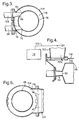
- the combustion chamber 22 is a tubular combustion chamber and comprises an inner cylindrical wall 48 which defines the primary, secondary and tertiary combustion zones 40, 42 and 44 and the dilution section 46.
- the upstream end of the cylindrical wall 48 has a conical head 50 which is provided with an aperture 52 coaxially with the axis of the cylindrical wall 48.
- a primary fuel and air mixing duct 54 is arranged to supply a mixture of fuel and air into the primary combustion zone 40 through the aperture 52 in the head 50 of the combustion chamber 22.
- the primary fuel and air mixing duct 54 is arranged coaxially with the axis of the cylindrical wall 46 of the combustion chamber 22 but may be arranged tangentially.
- the primary fuel and air mixing duct 54 comprises a first, radially inner, axial flow swirler 56, an annular member 58 surrounding and extending downstream from the first axial flow swirler 56 and a second, radially outer, axial flow swirler 60 surrounding the annular member 58.
- One of the axial flow swirlers 56, 60 is arranged to provide more swirl than the other of the axial flow swirlers 60, 56 such that there is residual swirl at the entry into the primary combustion zone 40 of the combustion chamber 22.
- the residual swirl enhances the primary flow reversal R to sustain the combustion process.
- a primary fuel injector nozzle 62 is arranged coaxially within the first axial flow swirler 56, to supply fuel into the primary fuel and air mixing duct 54.
- the primary fuel injector 62 is a simplex fuel injector and is arranged to spray fuel onto the annular member 58, and the fuel is atomised and mixed with the air by the oppositely swirling flows of air from the axial flow swirlers 56 and 60.
- the primary combustion zone 40 is arranged to long enough to reduce carbon monoxide emissions and/or the external convection cooling reduces the quenching effect. Any carbon monoxide generated in the primary combustion zone 40 is consumed in the secondary combustion zone 42.
- a first air duct 64 supplies heated air from the heat exchanger 20 to the primary fuel and air mixing duct 54.
- the first air duct 64 comprises a first valve 66 which is adjustable to vary the amount of air supplied to the primary fuel and air mixing duct 54.
- the first valve 66 is adjusted by an actuator 68.
- the first valve 66 is a two position butterfly valve, but it may be any other suitable two position valve or a multi position valve.
- the first air duct 64 also comprises an air flow measuring device 70, for example a low loss Corioli meter, a venturi meter or other low pressure loss velocity measuring device to accurately measure the air flow to the primary fuel and air mixing duct 54.
- the flow measuring device 70 sends a signal corresponding to the amount of air flowing to the primary fuel and air mixing duct 54 via electrical connector 72 to a processor 74.
- a secondary fuel and air mixing duct 78 is arranged to supply a mixture of fuel and air into the secondary combustion zone 42 through an aperture 76 in the cylindrical wall 48 of the combustion chamber 22.
- the secondary fuel and air mixing duct 78 is arranged tangentially with the axis of the cylindrical wall 46 of the combustion chamber 22.
- the secondary fuel and air mixing duct 78 is arranged to direct the fuel and air mixture in a tangential direction and also with a downstream component to minimise interference with the primary combustion zone 40.
- the secondary fuel and air mixing duct 78 comprises a third, radially inner, axial flow swirler 80, an annular member 82 surrounding and extending downstream from the third axial flow swirler 80 and a fourth, radially outer, axial flow swirler 84 surrounding the annular member 82.
- the axial flow swirlers 80, 84 are arranged to provide substantially equal swirl or low residual swirl.
- a secondary fuel injector nozzle 86 is arranged coaxially within the third axial flow swirler 80, to supply fuel into the secondary fuel and air mixing duct 78.
- the secondary fuel injector 86 is a simplex fuel injector and is arranged to spray fuel onto the annular member 82, and the fuel is atomised and mixed with the air by the oppositely swirling flows of air from the axial flow swirlers 80 and 84.
- the low residual swirl prevents flow recirculation and hence combustion takes place in the secondary combustion zone 42 remote from the wall 48 of the combustion chamber 22 and this ensures low emissions of carbon monoxide (CO). If there was a residual swirl and hence a flow recirculation film cooling air would be entrained causing high carbon monoxide emissions.
- a second air duct 88 supplies heated air from the heat exchanger 20 to the secondary fuel and air mixing duct 78.
- the second air duct 88 comprises a second valve 90 which is adjustable to vary the amount of air supplied to the secondary fuel and air mixing duct 78.
- the second valve 90 is adjusted by an actuator 92.
- the second valve 90 is a two position butterfly valve, but it may be any other suitable two position valve or a multi position valve.
- the second air duct 88 also comprises an air flow measuring device 92, for example a low loss Corioli meter, a venturi meter or other low pressure loss velocity measuring device to accurately measure the air flow to the secondary fuel and air mixing duct 78.
- the flow measuring device 92 sends a signal corresponding to the amount of air flowing to the secondary fuel and air mixing duct 78 via electrical connector 94 to the processor 74.
- a tertiary fuel and air mixing duct 98 is arranged to supply a mixture of fuel and air into the tertiary combustion zone 44 through an aperture 96 in the cylindrical wall 48 of the combustion chamber 22.
- the tertiary fuel and air mixing duct 98 is arranged tangentially with the axis of the cylindrical wall 46 of the combustion chamber 22.
- the tertiary fuel and air mixing duct 98 is arranged to direct the fuel and air mixture in the opposite tangential direction to the secondary fuel and air mixing duct 78 and also with a downstream component to minimise interference with the secondary combustion zone 42.
- the tertiary fuel and air mixing duct 98 comprises a fifth, radially inner, axial flow swirler 100, an annular member 102 surrounding and extending downstream from the fifth axial flow swirler 100 and a sixth, radially outer, axial flow swirler 104 surrounding the annular member 102.
- the axial flow swirlers 100, 104 are arranged to provide substantially equal swirl or low residual swirl.
- a tertiary fuel injector nozzle 106 is arranged coaxially within the fifth axial flow swirler 100, to supply fuel into the tertiary fuel and air mixing duct 98.
- the tertiary fuel injector 106 is a simplex fuel injector and is arranged to spray fuel onto the annular member 102, and the fuel is atomised and mixed with the air by the oppositely swirling flows of air from the axial flow swirlers 100 and 104.
- a third air duct 108 supplies heated air from the heat exchanger 20 to the tertiary fuel and air mixing duct 98.
- the third air duct 108 does not comprise a valve.
- the third air duct 108 comprises an air flow measuring device 110, for example a low loss Corioli meter, a venturi meter or other low pressure loss velocity measuring device to accurately measure the air flow to the tertiary fuel and air mixing duct 108.
- the flow measuring device 110 sends a signal corresponding to the amount of air flowing to the secondary fuel and air mixing duct 108 via electrical connector 112 to the processor 74.
- the combustion chamber 22 also comprises an outer cylindrical wall 114 spaced radially from the inner cylindrical wall 48 to define an annular passage 116 and the upstream end of the cylindrical wall 114 has a conical head 118 to close the annular passage 116 at its upstream end.
- the annular passage 116 is arranged to supply cooling air and dilution air around the inner cylindrical wall 48.
- the cylindrical wall 48 is cooled by the flow of air through the annular passage 116 and the dilution air flows through apertures 120 in the inner cylindrical wall 48 into the dilution section 46.
- a fourth air duct 122 supplies heated air from the heat exchanger 20 to the annular passage 116.
- the fourth air duct 122 does not comprise a valve.
- the fourth air duct 122 comprises an air flow measuring device 124, for example a low loss Corioli meter, a venturi meter or other low pressure loss velocity measuring device to accurately measure the air flow to the annular passage 116.
- the flow measuring device 124 sends a signal corresponding to the amount of air flowing to the annular passage 116 via electrical connector 126 to the processor 74.
- the processor 74 analyses the signals from the air flow measuring devices 70, 92, 110 and 124 to determine the amount of air flowing to the primary fuel and air mixing duct 54, the secondary fuel and air mixing duct 78, the tertiary fuel and air mixing duct 98 and the annular passage 116 respectively.
- the processor 74 determines and precisely controls the amount of fuel supplied to the primary fuel and air mixing duct 54, the secondary fuel and air mixing duct 78, the tertiary fuel and air mixing duct 98 to ensure the emissions of NOx, carbon monoxide, and unburned hydrocarbons from the combustion chamber 22 are minimised through the full power range of the gas turbine engine 10, particularly at low powers.
- the processor 74 sends signals to fuel valves 128, 130 and 132, via electrical connectors 134, 136 and 138 respectively, which control the supply of fuel to the primary fuel injector 62, the secondary fuel injector 86 and the tertiary fuel injector 106 respectively.
- the secondary combustion zone 42 and tertiary combustion zone 44 are arranged such that they are not self stabilising, rather they are arranged such that the combustion is stabilised by the mixing of the hot gases from the upstream combustion stage.
- the first valve 66 and the second valve 90 are closed to limit the air flow to the primary mixing duct 54 and the secondary mixing duct 78 to about 50% of the maximum flow through the primary mixing duct 54 and the secondary mixing duct 78.
- the first valve 66 is opened and at power levels above about 6% power the second valve 90 is opened.
- the primary fuel injector 62 and the secondary fuel injector 86 only are supplied with fuel and at power levels above about 30% power the primary fuel injector 62, the secondary fuel injector 86 and the tertiary fuel injector 106 are supplied with fuel.
- about 5% of the total air flow is supplied to the primary fuel and air mixing duct 54 when the first valve 66 is closed and about 10% of the total air flow is supplied to the primary fuel and air mixing duct 54 when the first valve 66 is open.
- about 5% of the total air flow is supplied to the secondary fuel and air mixing duct 78 when the second valve 90 is closed and about 10% of the total air flow is supplied to the secondary fuel and air mixing duct 78 when the second valve 90 is open.
- about 10% of the total air flow is supplied to the tertiary fuel and air mixing duct 98 at all times.
- the first and second valves 66 and 90 respectively may be multi-position valves, this may allow the air flow to be redistributed to control, or minimise, noise by varying the air flow, combustion chamber residence time, the point of fuel injection and point of heat release.
- the engine provides a part load SFC curve which is comparable with a diesel engine, particularly in the idle to 25% power range. This is achieved by maintaining the cycle parameters (i.e. pressures and temperatures) substantially constant over a large portion of the power range by use of variable vanes. A further effect is to reduce the engine rotational speed variation required for a given power range, which reduces the acceleration time requirement because the angles of the variable vanes are adjustable at a faster rate than the rotational speed of the engine can change.
- the combustion chamber 22 of the present invention may be used in a gas turbine engine arrangement shown in figure 6.
- the gas turbine engine 150 comprises a first centrifugal air compressor 152 comprising a radial inlet duct 154 incorporating variable inlet guide vanes 156 and a centrifugal impeller (not shown).
- the centrifugal compressor 152 delivers air via a variable area radial diffuser 158 to a heat exchanger 160.
- the variable area radial diffuser 158 reduces the velocity of the air before it enters the heat exchanger 160.
- variable area inlet guide vanes 156 comprise an aerofoil cross section. These inlet guide vanes are fully open when full power is required thus allowing the air to reach the impeller without substantial swirl and even a small amount of anti-rotative swirl to ensure the maximum amount of flow is passed.
- the variable area inlet guide vanes 156 are positioned in a semi-closed state. This causes rotative swirl of the working fluid reaching the impeller inlet, which reduces the relative velocity, because the rotative swirl velocity is effectively subtracted from the rotational speed vector. Thus the mass flow of the working fluid at any given speed is reduced.
- the centrifugal impeller produces an increase in static pressure and absolute velocity. The working fluid leaves the impeller at approximately Mach 1.
- the working fluid passes into a variable area radial diffuser 158 which contributes to the compressor pressure rise by recovering velocity as static pressure.
- the diffuser vanes are pivoted so as to move in a tangential direction with respect to the diffuser and adjust the throat area. As these vanes are closed simultaneously with the variable inlet guide vanes, the leading edge incidence is optimised. In addition the degree of diffusion up to the throat is controlled. Too high an incidence or attempted diffusion would also result in surge. Surge is where the adverse flow conditions cause a high local pressure loss resulting in flow reversal as the pressure rise cannot be sustained.
- This working fluid is then passed through the heat exchanger 160, then into the combustion chamber 22 and then to a turbine 164.
- Fuel is burned in the combustion chamber 22 and the resulting combustion products flow into the turbine 164 which is drivingly connected to the centrifugal compressor 152.
- the turbine 164 incorporates a variable area nozzle 166 which is operated so as to close the vanes as power demand falls thus reducing flow capacity.
- the turbine design expansion ratio is chosen high enough to ensure choked operation over most of the power range, thus ensuring flow capacity remains proportional to nozzle throat area. If unchoked, the flow capacity would be set by the expansion ratio and rotor throat area, sufficient variation could not be achieved via the nozzle area.
- the turbine 164 is also connected to an output shaft 168 which drives an electrical generator 170.
- the electrical generator 170 is arranged to supply electricity to one or more electrical motors 174 via electrical connections 172, for example, for driving the wheels 178 of a motor vehicle or a propeller of a marine vessel.
- the hot exhaust gases from the turbine 164 are directed back into the heat exchanger 160 to directly pre-heat the air from the diffuser 158 before it enters the combustion chamber 22.
- the combustion chamber 22 is the same as that described previously with reference to figures 2 to 5.
- the engine provides a part load SFC curve which is comparable with a diesel engine, particularly in the idle to 25% power range. This is achieved by maintaining the cycle parameters (i.e. pressures and temperatures) substantially constant over a whole power range by use of variable vanes. A further effect is to reduce the engine rotational speed variation required for a given power range, which reduces the acceleration time requirement because the angles of the variable vanes are adjustable at a faster rate than the rotational speed of the engine can change.
- variable vanes at the inlet to the centrifugal compressor, diffuser, first turbine and power turbine is to allow reduced mass flow whilst maintaining pressure ratio and efficiency.
- the variable vanes are adjusted to reduce the mass flow for the compressor, diffuser and all the turbines as the power demand falls, or conversely the variable vanes are adjusted to increase mass flow for the compressor, diffuser and all the turbines over a predetermined wide power range.
- the values of the cycle temperature, speed and pressure ratio are maintained substantially constant over the predetermined wide power range and therefore the specific fuel consumption is maintained substantially constant over this predetermined wide power range.
- variable area inlet guide vanes for the centrifugal compressor enhance the centrifugal compressor's ability to deliver reduced mass flow at constant engine rotational speed.
- the emission levels of the combustion chamber assembly will be less than 0.5gm per kw hr.
- combustion chamber assembly comprising a single primary fuel and air mixing duct, a single secondary fuel and air mixing duct and a single tertiary fuel and air mixing duct
- combustion chamber assemblies each one of which comprising a single primary fuel and air mixing duct, a single secondary fuel and air mixing duct and a single tertiary fuel and air mixing duct for the respective primary, secondary and tertiary combustion stages.
- a single combustion chamber assembly comprising a plurality of primary fuel and air mixing ducts, a plurality of secondary fuel and air mixing ducts and a plurality of tertiary fuel and air mixing ducts for the primary, secondary and tertiary combustion stages.
- each combustion chamber comprising a plurality of combustion stages, at least two of which have a respective mixing duct with means to vary the air flow into the respective combustion stage.
- the combustion chamber may comprise two combustion stages with means to vary the air flow into both of the combustion stages, three combustion stages with means to vary the air flow to two or all three of the combustion stages or four combustion stages with means to vary the air flow to two, three or all four of the combustion stages.
- the primary fuel and air mixing ducts may be arranged such that they supply the fuel and air into the combustion chamber at axially spaced locations, at different angles to the combustion chamber axis and at different angles in a tangential sense to vary the heat release over the combustion chamber length to reduce, minimise noise.
- the secondary fuel and air mixing ducts may be arranged such that they supply the fuel and air into the combustion chamber at axially spaced locations, at different angles to the combustion chamber axis and at different angles in a tangential sense to vary the heat release over the combustion chamber length to reduce, minimise noise.
- the tertiary fuel and air mixing ducts may be arranged such that they supply the fuel and air into the combustion chamber at axially spaced locations, at different angles to the combustion chamber axis and at different angles in a tangential sense to vary the heat release over the combustion chamber length to reduce, minimise noise.
Landscapes
- Engineering & Computer Science (AREA)
- Chemical & Material Sciences (AREA)
- Combustion & Propulsion (AREA)
- Mechanical Engineering (AREA)
- General Engineering & Computer Science (AREA)
Claims (28)
- Brennkammeraufbau mit wenigstens einer Brennkammer (22), welche die folgenden Merkmale aufweist: eine primäre Verbrennungszone (40); eine sekundäre Verbrennungszone (42); wenigstens einen primären Brennstoff/Luft-Mischkanal (54); primäre Brennstoffinjektormittel (62), um Brennstoff dem primären Brennstoff/Luft-Mischkanal (54) zuzuführen, wobei der primäre Brennstoff/Luft-Mischkanal (54) so angeordnet und ausgebildet ist, dass Brennstoff und Luft in die primäre Verbrennungszone (40) eingeleitet werden; wenigstens einen sekundären Brennstoff/Luft-Mischkanal (78); sekundäre Brennstoffinjektormittel (86), um Brennstoff dem sekundären Brennstoff/Luft-Mischkanal (78) zuzuführen, wobei der sekundäre Brennstoff/Luft-Mischkanal (78) derart angeordnet und ausgebildet ist, dass Brennstoff und Luft in die sekundäre Verbrennungszone (42) eingeführt werden; erste Ventilmittel (66), um die Luftzufuhr nach dem wenigstens einen primären Brennstoff/Luft-Mischkanal (54) zu steuern; und zweite Ventilmittel (90), um die Zufuhr von Luft nach dem sekundären Brennstoff/Luft-Mischkanal (78) zu steuern,
dadurch gekennzeichnet, dass jeder sekundäre Brennstoff/Luft-Mischkanal (78) zwei axiale Strömungsverwirbelungs-Einrichtungen (80, 84) aufweist, die koaxial angeordnet sind, um Luft in entgegengesetzten Richtungen zu verwirbeln, wobei die sekundären Brennstoffinjektormittel (86) so angeordnet und ausgebildet sind, dass Brennstoff koaxial zu den Strömungsverwirbelungs-Einrichtungen (80, 84) in den sekundären Brennstoff/Luft-Mischkanal (78) eingeführt wird. - Brennkammeraufbau nach Anspruch 1, bei weichem der primäre Brennstoff/Luft-Mischkanal (54) so angeordnet und ausgebildet ist, dass der Brennstoff und die Luft in die primäre Verbrennungszone (40) mit einer stromab gerichteten Strömungskomponente eingeführt werden.
- Brennkammeraufbau nach Anspruch 1 oder Anspruch 2, bei welchem der sekundäre Brennstoff/Luft-Mischkanal (78) so angeordnet und ausgebildet ist, dass der Brennstoff und die Luft in die sekundäre Verbrennungszone (42) mit einer tangentialen und einer stromab gerichteten Strömungskomponente eingeführt werden.
- Brennkammeraufbau nach einem der Ansprüche 1 bis 3, bei welchem jeder primäre Brennstoff/Luft-Mischkanal (54) zwei axiale Strömungsverwirbelungs-Einrichtungen (56, 60) aufweist, die koaxial angeordnet sind, um die Luft in entgegengesetzten Richtungen zu verwirbeln, wobei die primären Brennstoffinjektormittel (62) so angeordnet und ausgebildet sind, dass Brennstoff koaxial zu den axialen Strömungsverwirbelungs-Einrichtungen (56, 60) in den primären Brennstoff/Luft-Mischkanal (54) eingeführt wird.
- Brennkammeraufbau nach einem der Ansprüche 1 bis 4, bei welchem die Brennkammer (22) folgende Merkmale aufweist: eine tertiäre Verbrennungszone (44); wenigstens einen tertiären Brennstoff/Luft-Mischkanal (98); tertiäre Brennstoffinjektormittel (106), um Brennstoff dem tertiären Brennstoff/Luft-Mischkanal (98) zuzuführen; Mittel zur Zufuhr von Luft nach dem tertiären Brennstoff/Luft-Mischkanal (98), wobei der tertiäre Brennstoff/Luft-Mischkanal (98) so angeordnet und ausgebildet ist, dass Brennstoff und Luft in die tertiäre Verbrennungszone (44) eingeführt werden.
- Brennkammeraufbau nach Anspruch 5, bei welchem der tertiäre Brennstoff/Luft-Mischkanal (98) so angeordnet und ausgebildet ist, dass Brennstoff und Luft in die tertiäre Verbrennungszone (44) mit einer entgegengesetzt zu der im sekundären Brennstoff/Luft-Mischkanal (78) verlaufenden tangentialen Komponente und einer stromab gerichteten Komponente eingeführt werden.
- Brennkammeraufbau nach Anspruch 5 oder Anspruch 6, bei welchem der tertiäre Brennstoff/Luft-Mischkanal (98) zwei axiale Strömungsverwirbelungs-Einrichtungen (102, 104) aufweist, die koaxial angeordnet sind, um die Luft in entgegengesetzten Richtungen zu verwirbeln, wobei die tertiären Brennstoffinjektormittel (106) so angeordnet und ausgebildet sind, dass der Brennstoff koaxial zu den axialen Strömungsverwirbelungs-Einrichtungen (102, 104) in den tertiären Brennstoff/Luft-Mischkanal (98) eingeführt wird.
- Brennkammeraufbau nach einem der Ansprüche 1 bis 7, bei welchem mehrere primäre Brennstoff/Luft-Mischkanäle (54) und mehrere sekundäre Brennstoff/Luft-Mischkanäle (78) vorgesehen sind.
- Brennkammer nach einem der Ansprüche 1 bis 7, bei welcher mehrere primäre Brennstoff/Luft-Mischkanäle (54), mehrere sekundäre Brennstoff/Luft-Mischkanäle (78) und mehrere tertiäre Brennstoff/Luft-Mischkanäle (98) vorgesehen sind.
- Brennkammeraufbau nach einem der Ansprüche 1 bis 9, bei welchem der primäre Brennstoff/Luft-Mischkanal (54) so angeordnet und ausgebildet ist, dass Brennstoff und Luft in die Brennkammer (22) mit einer tangential und einer stromab gerichteten Strömungskomponente injiziert werden.
- Brennkammeraufbau nach einem der Ansprüche 1 bis 10, bei welchem die ersten und zweiten Ventilmittel (66, 90) Zweiwegeventile sind.
- Brennkammeraufbau nach einem der Ansprüche 1 bis 11, bei welchem die ersten und zweiten Ventilmittel (66, 90) Mehrwegeventile sind.
- Brennkammeraufbau nach Anspruch 4, bei welchem eine der axialen Strömungsverwirbelungs-Einrichtungen (56) in dem primären Brennstoff/Luft-Mischkanal (54) eine höhere Verwirbelung als die andere axiale Strömungsverwirbelungs-Einrichtung (60) bewirkt, derart, dass eine Restverwirbelung durch die beiden axialen Strömungsverwirbelungs-Einrichtungen (56, 60) erzeugt wird.
- Brennkammeraufbau nach einem der Ansprüche 1 bis 13, bei welchem die axialen Strömungsverwirbelungs-Einrichtungen (80, 84) in dem sekundären Brennstoff/Luft-Mischkanal (78) gleiche und entgegengesetzte Verwirbelungen bewirken, derart, dass keine Restverwirbelung durch die beiden axialen Strömungsverwirbelungs-Einrichtungen (80, 84) zustande kommt.
- Brennkammeraufbau nach Anspruch 7, bei welchem die axialen Strömungsverwirbelungs-Einrichtungen (102, 104) in dem tertiären Brennstoff/Luft-Mischkanal (98) eine im Wesentlichen gleiche und entgegengesetzte Verwirbelung derart bewirken, dass keine Restverwirbelung durch die beiden axialen Strömungsverwirbelungs-Einrichtungen (102, 104) zustande kommt.
- Brennkammeraufbau nach einem der Ansprüche 1 bis 15, welcher Mittel (70, 92) aufweist, um die Luftströmung nach dem primären und dem sekundären Brennstoff/Luft-Mischkanal (54, 78) zu messen und weiter Mittel (74, 128, 130) vorgesehen sind, um die Brennstoffzufuhr nach den primären und sekundären Brennstoffinjektormitteln (62, 86) gemäß den gemessenen Luftströmungen nach den primären und sekundären Brennstoff/Luft-Mischkanälen (54, 78) derart einzustellen, dass die Emissionen aus der Brennkammer (22) vermindert werden.
- Brennkammeraufbau nach einem der Ansprüche 5 bis 7, welcher Mittel aufweist, um die Luftströmung nach den primären, den sekundären und den tertiären Brennstoff/Luft-Mischkanälen (54, 78, 98) zu messen und bei welchem weiter Mittel (74, 128, 130, 132) vorgesehen sind, um die Brennstoffzufuhr nach den primären, den sekundären und den tertiären Brennstoffinjektormitteln (62, 86, 106) gemäß den gemessenen Luftströmungen nach den primären, den sekundären und den tertiären Brennstoff/Luft-Mischkanälen (54, 78, 98) so einzustellen, dass Emissionen aus der Brennkammer (22) vermindert werden.
- Brennkammeraufbau nach Anspruch 17, bei welchem die Mittel (70, 92, 110) zur Messung der Luftströmung nach den primären, sekundären und tertiären Brennstoff/Luft-Mischkanälen (54, 78, 98) Niederdruck-Koriolis-Messgeräte sind.
- Brennkammeraufbau nach den Ansprüchen 16 und 17 oder Anspruch 18, welcher Mittel (124) aufweist, um die Kühlluftströmung und die Verdünnungsluftströmung nach der Brennkammer (22) zu messen.
- Brennkammeraufbau nach Anspruch 19, bei welchem die Mittel (124) zur Messung der Kühlluftströmung und der Verdünnungsluftströmung nach der Brennkammer (22) ein Niederdruck-Koriolis-Messgerät aufweisen.
- Verfahren zum Betrieb eines Brennkammeraufbaus, der eine Brennkammer (22) mit den folgenden Merkmalen aufweist: eine primäre Verbrennungszone (40); eine sekundäre Verbrennungszone (42); wenigstens einen primären Brennstoff/Luft-Mischkanal (54); primäre Brennstoffinjektormittel (62), um Brennstoff dem primären Brennstoff/Luft-Mischkanal (54) zuzuführen; erste Ventilmittel (66), um die Luftzufuhr nach dem wenigstens einen Brennstoff/Luft-Mischkanal (54) einzustellen, wobei der primäre Brennstoff/Luft-Mischkanal (54) so angeordnet und ausgebildet ist, dass Brennstoff und Luft in die primäre Verbrennungszone (40) eingeführt werden; wenigstens einen sekundären Brennstoff/Luft-Mischkanal (78); sekundäre Brennstoffinjektormittel (86), um Brennstoff dem sekundären Brennstoff/Luft-Mischkanal (78) zuzuführen; zweite Ventilmittel (90), um die Luftzufuhr nach dem sekundären Brennstoff/Luft-Mischkanal (78) zu steuern, wobei der sekundäre Brennstoff/Luft-Mischkanal (78) so angeordnet ist, dass Brennstoff und Luft in die sekundäre Verbrennungszone (42) eingeführt werden, wobei das Verfahren die folgenden Schritte umfasst: es werden die ersten Ventilmittel (66) und die zweiten Ventilmittel (90) in einem ersten Betriebsmodus geschlossen, in einem zweiten Betriebsmodus werden die ersten Ventilmittel (66) geöffnet und die zweiten Ventilmittel (90) geschlossen gehalten und in einem dritten Betriebsmodus werden die ersten Ventilmittel (66) und die zweiten Ventilmittel (90) geöffnet.
- Verfahren nach Anspruch 21, bei welchem die Brennkammer (22) die folgenden Merkmale aufweist: eine tertiäre Verbrennungszone (44); wenigstens einen tertiären Brennstoff/Luft-Mischkanal (98); tertiäre Brennstoffinjektormittel (106), um Brennstoff dem tertiären Brennstoff/Luft-Mischkanal (98) zuzuführen; Mittel zur Zufuhr von Luft nach dem tertiären Brennstoff/Luft-Mischkanal (98), wobei der tertiäre Brennstoff/Luft-Mischkanal (98) derart angeordnet und ausgebildet ist, dass Brennstoff und Luft in die tertiäre Verbrennungszone (44) eingeführt werden.
- Verfahren nach Anspruch 22, bei welchem in der Schließstellung der ersten Ventilmittel (66) die Luftströmung nach dem primären Brennstoff/Luft-Mischkanal (54) um 50 % im Vergleich mit der Öffnungsstellung der ersten Ventilmittel (66) verringert wird.
- Verfahren nach Anspruch 22 oder 23, bei welchem in der Schließstellung der zweiten Ventilmittel (90) die Luftströmung nach dem sekundären Brennstoff/Luft-Mischkanal (78) um etwa 50 % im Vergleich zur Öffnungsstellung der zweiten Ventilmittel (90) verringert wird.
- Verfahren nach einem der Ansprüche 22 bis 24, bei welchem etwa 5 % der Gesamtluftströmung dem primären Brennstoff/Luft-Mischkanal (54) zugeführt werden, bei welchem etwa 5 % der Gesamtluftströmung dem sekundären Brennstoff/Luft-Mischkanal (78) zugeführt werden, bei dem etwa 10 % der Gesamtluftströmung dem tertiären Brennstoff/Luft-Mischkanal (98) zugeführt werden und bei welchem der Rest der Luft als Verdünnungsluft und Kühlluft der Brennkammer (22) in dem ersten Betriebsmodus zugeführt wird.
- Verfahren nach einem der Ansprüche 22 bis 25, bei welchem etwa 10 % der Gesamtluftströmung dem primären Brennstoff/Luft-Mischkanal (54) zugeführt werden, bei dem etwa 5 % der Gesamtluftströmung dem sekundären Brennstoff/Luft-Mischkanal (78) zugeführt werden, bei dem etwa 10 % der Gesamtluftströmung dem tertiären Brennstoff/Luft-Mischkanal (98) zugeführt werden und bei dem der Rest der Luft als Verdünnungsluft und Kühlluft der Brennkammer (22) in dem zweiten Betriebsmodus zugeführt wird.
- Verfahren nach einem der Ansprüche 22 bis 26, bei welchem etwa 10 % der Gesamtluftströmung dem primären Brennstoff/Luft-Mischkanal (54) zugeführt werden, bei dem etwa 10 % der Gesamtluftströmung dem sekundären Brennstoff/Luft-Mischkanal (78) zugeführt werden, bei dem etwa 10 % der Gesamtluftströmung dem tertiären Brennstoff/Luft-Mischkanal (98) zugeführt werden und bei dem der Rest der Luft als Verdünnungsluft und Kühlluft der Brennkammer (22) in dem dritten Betriebsmodus zugeführt wird.
- Verfahren nach einem der Ansprüche 22 bis 27, bei welchem die Strömungsrate der dem primären Brennstoff/Luft-Mischkanal (54) zugeführten Luft gemessen wird, bei welchem die Strömungsrate der dem sekundären Brennstoff/Luft-Mischkanal (78) zugeführten Luft gemessen wird, bei welchem die Strömungsrate der dem tertiären Brennstoff/Luft-Mischkanal (98) zugeführten Luft gemessen wird, bei welchem die Strömungsrate des dem primären Brennstoffinjektor (62) zugeführten Brennstoffs so eingestellt wird, dass ein erstes vorbestimmtes Brennstoff/Luft-Verhältnis im primären Brennstoff/Luft-Mischkanal (54) erhalten wird, bei welchem die Strömungsrate des dem sekundären Brennstoffinjektor (86) zugeführten Brennstoffs so eingestellt wird, dass ein zweites vorbestimmtes Brennstoff/Luft-Verhältnis in dem sekundären Brennstoff/Luft-Mischkanal (78) erhalten wird und bei welchem die Strömungsrate des dem tertiären Brennstoffinjektor (106) zugeführten Brennstoffs so eingestellt wird, dass ein drittes vorbestimmtes Brennstoff/Luft-Verhältnis in dem tertiären Brennstoff/Luft-Mischkanal (98) erhalten wird.
Applications Claiming Priority (2)
| Application Number | Priority Date | Filing Date | Title |
|---|---|---|---|
| GBGB9911867.1A GB9911867D0 (en) | 1999-05-22 | 1999-05-22 | A combustion chamber assembly and a method of operating a combustion chamber assembly |
| GB9911867 | 1999-05-22 |
Publications (2)
| Publication Number | Publication Date |
|---|---|
| EP1055879A1 EP1055879A1 (de) | 2000-11-29 |
| EP1055879B1 true EP1055879B1 (de) | 2004-12-22 |
Family
ID=10853916
Family Applications (1)
| Application Number | Title | Priority Date | Filing Date |
|---|---|---|---|
| EP00303463A Expired - Lifetime EP1055879B1 (de) | 1999-05-22 | 2000-04-25 | Brennkammeranordnung und Verfahren zum Betrieb einer Brennkammeranordnung |
Country Status (4)
| Country | Link |
|---|---|
| US (1) | US6332313B1 (de) |
| EP (1) | EP1055879B1 (de) |
| DE (1) | DE60016832T2 (de) |
| GB (1) | GB9911867D0 (de) |
Cited By (2)
| Publication number | Priority date | Publication date | Assignee | Title |
|---|---|---|---|---|
| US7955048B2 (en) | 2006-08-25 | 2011-06-07 | Alstom Technology Ltd. | Steam turbines |
| CN103542427A (zh) * | 2012-07-09 | 2014-01-29 | 阿尔斯通技术有限公司 | 燃气涡轮燃烧系统 |
Families Citing this family (97)
| Publication number | Priority date | Publication date | Assignee | Title |
|---|---|---|---|---|
| US6539721B2 (en) * | 2001-07-10 | 2003-04-01 | Pratt & Whitney Canada Corp. | Gas-liquid premixer |
| DE60313392T2 (de) * | 2002-05-16 | 2007-08-09 | Rolls-Royce Plc | Gasturbine |
| EP1819964A2 (de) | 2004-06-11 | 2007-08-22 | Vast Power Systems, Inc. | Vorrichtung und verfahren zur emissionsarmen verbrennung |
| CA2621958C (en) * | 2005-09-13 | 2015-08-11 | Thomas Scarinci | Gas turbine engine combustion systems |
| US20070089427A1 (en) | 2005-10-24 | 2007-04-26 | Thomas Scarinci | Two-branch mixing passage and method to control combustor pulsations |
| JP2007113888A (ja) * | 2005-10-24 | 2007-05-10 | Kawasaki Heavy Ind Ltd | ガスタービンエンジンの燃焼器構造 |
| US20070107437A1 (en) * | 2005-11-15 | 2007-05-17 | Evulet Andrei T | Low emission combustion and method of operation |
| US7886539B2 (en) * | 2007-09-14 | 2011-02-15 | Siemens Energy, Inc. | Multi-stage axial combustion system |
| WO2009120779A2 (en) | 2008-03-28 | 2009-10-01 | Exxonmobil Upstream Research Company | Low emission power generation and hydrocarbon recovery systems and methods |
| WO2009121008A2 (en) | 2008-03-28 | 2009-10-01 | Exxonmobil Upstream Research Company | Low emission power generation and hydrocarbon recovery systems and methods |
| US8176739B2 (en) * | 2008-07-17 | 2012-05-15 | General Electric Company | Coanda injection system for axially staged low emission combustors |
| EP2344738B1 (de) | 2008-10-14 | 2019-04-03 | Exxonmobil Upstream Research Company | Verfahren und system zur kontrolle von verbrennungsprodukten |
| US8382436B2 (en) | 2009-01-06 | 2013-02-26 | General Electric Company | Non-integral turbine blade platforms and systems |
| US8262345B2 (en) | 2009-02-06 | 2012-09-11 | General Electric Company | Ceramic matrix composite turbine engine |
| CN102459850B (zh) | 2009-06-05 | 2015-05-20 | 埃克森美孚上游研究公司 | 燃烧器系统和使用燃烧器系统的方法 |
| US20110167792A1 (en) * | 2009-09-25 | 2011-07-14 | James Edward Johnson | Adaptive engine |
| US20110167831A1 (en) * | 2009-09-25 | 2011-07-14 | James Edward Johnson | Adaptive core engine |
| US20110167784A1 (en) * | 2009-09-25 | 2011-07-14 | James Edward Johnson | Method of operating a convertible fan engine |
| MY158169A (en) | 2009-11-12 | 2016-09-15 | Exxonmobil Upstream Res Co | Low emission power generation and hydrocarbon recovery systems and methods |
| IT1400053B1 (it) * | 2010-05-24 | 2013-05-17 | Nuovo Pignone Spa | Metodi e sistemi per ugelli di ingresso a geometria variabile per uso in turboespansori. |
| MX341981B (es) | 2010-07-02 | 2016-09-08 | Exxonmobil Upstream Res Company * | Combustion estequiometrica con recirculacion de gas de escape y enfriador de contacto directo. |
| BR112012031512A2 (pt) | 2010-07-02 | 2016-11-08 | Exxonmobil Upstream Res Co | sistemas e processos de geração de energia de baixa emissão |
| MY156099A (en) | 2010-07-02 | 2016-01-15 | Exxonmobil Upstream Res Co | Systems and methods for controlling combustion of a fuel |
| CN102985665A (zh) | 2010-07-02 | 2013-03-20 | 埃克森美孚上游研究公司 | 低排放三循环动力产生系统和方法 |
| MX354587B (es) | 2010-07-02 | 2018-03-12 | Exxonmobil Upstream Res Company Star | Combustión estequiométrica de aire enriquecido con recirculación de gas de escape. |
| JP6193759B2 (ja) | 2010-08-06 | 2017-09-06 | エクソンモービル アップストリーム リサーチ カンパニー | 化学量論的燃焼の最適化システム及び方法 |
| WO2012018458A1 (en) | 2010-08-06 | 2012-02-09 | Exxonmobil Upstream Research Company | System and method for exhaust gas extraction |
| TWI593872B (zh) | 2011-03-22 | 2017-08-01 | 艾克頌美孚上游研究公司 | 整合系統及產生動力之方法 |
| TWI564474B (zh) | 2011-03-22 | 2017-01-01 | 艾克頌美孚上游研究公司 | 於渦輪系統中控制化學計量燃燒的整合系統和使用彼之產生動力的方法 |
| TWI563166B (en) | 2011-03-22 | 2016-12-21 | Exxonmobil Upstream Res Co | Integrated generation systems and methods for generating power |
| TWI563165B (en) | 2011-03-22 | 2016-12-21 | Exxonmobil Upstream Res Co | Power generation system and method for generating power |
| EP2602550A1 (de) * | 2011-12-09 | 2013-06-12 | Siemens Aktiengesellschaft | Brennkammer für eine Gasturbine und Gasturbine |
| US9810050B2 (en) | 2011-12-20 | 2017-11-07 | Exxonmobil Upstream Research Company | Enhanced coal-bed methane production |
| US9353682B2 (en) | 2012-04-12 | 2016-05-31 | General Electric Company | Methods, systems and apparatus relating to combustion turbine power plants with exhaust gas recirculation |
| US9784185B2 (en) | 2012-04-26 | 2017-10-10 | General Electric Company | System and method for cooling a gas turbine with an exhaust gas provided by the gas turbine |
| US10273880B2 (en) | 2012-04-26 | 2019-04-30 | General Electric Company | System and method of recirculating exhaust gas for use in a plurality of flow paths in a gas turbine engine |
| US9803865B2 (en) | 2012-12-28 | 2017-10-31 | General Electric Company | System and method for a turbine combustor |
| US9611756B2 (en) | 2012-11-02 | 2017-04-04 | General Electric Company | System and method for protecting components in a gas turbine engine with exhaust gas recirculation |
| US9869279B2 (en) | 2012-11-02 | 2018-01-16 | General Electric Company | System and method for a multi-wall turbine combustor |
| US10215412B2 (en) | 2012-11-02 | 2019-02-26 | General Electric Company | System and method for load control with diffusion combustion in a stoichiometric exhaust gas recirculation gas turbine system |
| US9599070B2 (en) | 2012-11-02 | 2017-03-21 | General Electric Company | System and method for oxidant compression in a stoichiometric exhaust gas recirculation gas turbine system |
| US9708977B2 (en) | 2012-12-28 | 2017-07-18 | General Electric Company | System and method for reheat in gas turbine with exhaust gas recirculation |
| US9574496B2 (en) | 2012-12-28 | 2017-02-21 | General Electric Company | System and method for a turbine combustor |
| US10107495B2 (en) | 2012-11-02 | 2018-10-23 | General Electric Company | Gas turbine combustor control system for stoichiometric combustion in the presence of a diluent |
| US10138815B2 (en) | 2012-11-02 | 2018-11-27 | General Electric Company | System and method for diffusion combustion in a stoichiometric exhaust gas recirculation gas turbine system |
| US9631815B2 (en) | 2012-12-28 | 2017-04-25 | General Electric Company | System and method for a turbine combustor |
| US10208677B2 (en) | 2012-12-31 | 2019-02-19 | General Electric Company | Gas turbine load control system |
| US9581081B2 (en) | 2013-01-13 | 2017-02-28 | General Electric Company | System and method for protecting components in a gas turbine engine with exhaust gas recirculation |
| US9512759B2 (en) | 2013-02-06 | 2016-12-06 | General Electric Company | System and method for catalyst heat utilization for gas turbine with exhaust gas recirculation |
| US9938861B2 (en) | 2013-02-21 | 2018-04-10 | Exxonmobil Upstream Research Company | Fuel combusting method |
| TW201502356A (zh) | 2013-02-21 | 2015-01-16 | Exxonmobil Upstream Res Co | 氣渦輪機排氣中氧之減少 |
| WO2014133406A1 (en) | 2013-02-28 | 2014-09-04 | General Electric Company | System and method for a turbine combustor |
| US20140250945A1 (en) | 2013-03-08 | 2014-09-11 | Richard A. Huntington | Carbon Dioxide Recovery |
| TW201500635A (zh) | 2013-03-08 | 2015-01-01 | Exxonmobil Upstream Res Co | 處理廢氣以供用於提高油回收 |
| WO2014137648A1 (en) | 2013-03-08 | 2014-09-12 | Exxonmobil Upstream Research Company | Power generation and methane recovery from methane hydrates |
| US9618261B2 (en) | 2013-03-08 | 2017-04-11 | Exxonmobil Upstream Research Company | Power generation and LNG production |
| US9631542B2 (en) | 2013-06-28 | 2017-04-25 | General Electric Company | System and method for exhausting combustion gases from gas turbine engines |
| US9617914B2 (en) | 2013-06-28 | 2017-04-11 | General Electric Company | Systems and methods for monitoring gas turbine systems having exhaust gas recirculation |
| TWI654368B (zh) | 2013-06-28 | 2019-03-21 | 美商艾克頌美孚上游研究公司 | 用於控制在廢氣再循環氣渦輪機系統中的廢氣流之系統、方法與媒體 |
| US9835089B2 (en) | 2013-06-28 | 2017-12-05 | General Electric Company | System and method for a fuel nozzle |
| US20160069264A1 (en) * | 2013-07-22 | 2016-03-10 | Joseph D. Brostmeyer | Gas turbine engine with turbine cooling and combustor air preheating |
| US9587510B2 (en) | 2013-07-30 | 2017-03-07 | General Electric Company | System and method for a gas turbine engine sensor |
| US9903588B2 (en) | 2013-07-30 | 2018-02-27 | General Electric Company | System and method for barrier in passage of combustor of gas turbine engine with exhaust gas recirculation |
| US9951658B2 (en) | 2013-07-31 | 2018-04-24 | General Electric Company | System and method for an oxidant heating system |
| US10030588B2 (en) | 2013-12-04 | 2018-07-24 | General Electric Company | Gas turbine combustor diagnostic system and method |
| US9752458B2 (en) | 2013-12-04 | 2017-09-05 | General Electric Company | System and method for a gas turbine engine |
| US10227920B2 (en) | 2014-01-15 | 2019-03-12 | General Electric Company | Gas turbine oxidant separation system |
| US9915200B2 (en) | 2014-01-21 | 2018-03-13 | General Electric Company | System and method for controlling the combustion process in a gas turbine operating with exhaust gas recirculation |
| US9863267B2 (en) | 2014-01-21 | 2018-01-09 | General Electric Company | System and method of control for a gas turbine engine |
| US10079564B2 (en) | 2014-01-27 | 2018-09-18 | General Electric Company | System and method for a stoichiometric exhaust gas recirculation gas turbine system |
| US10047633B2 (en) | 2014-05-16 | 2018-08-14 | General Electric Company | Bearing housing |
| US9869190B2 (en) | 2014-05-30 | 2018-01-16 | General Electric Company | Variable-pitch rotor with remote counterweights |
| US10060359B2 (en) | 2014-06-30 | 2018-08-28 | General Electric Company | Method and system for combustion control for gas turbine system with exhaust gas recirculation |
| US9885290B2 (en) | 2014-06-30 | 2018-02-06 | General Electric Company | Erosion suppression system and method in an exhaust gas recirculation gas turbine system |
| US10655542B2 (en) | 2014-06-30 | 2020-05-19 | General Electric Company | Method and system for startup of gas turbine system drive trains with exhaust gas recirculation |
| GB201414661D0 (en) * | 2014-08-19 | 2014-10-01 | Rolls Royce Plc | Gas turbine engine and method of operation |
| GB201414662D0 (en) * | 2014-08-19 | 2014-10-01 | Rolls Royce Plc | Method of operation of a gas turbine engine |
| US10072510B2 (en) | 2014-11-21 | 2018-09-11 | General Electric Company | Variable pitch fan for gas turbine engine and method of assembling the same |
| US20160160761A1 (en) * | 2014-12-09 | 2016-06-09 | United Technologies Corporation | Gas Turbine Engine With Single Turbine Driving Two Compressors |
| US9869247B2 (en) | 2014-12-31 | 2018-01-16 | General Electric Company | Systems and methods of estimating a combustion equivalence ratio in a gas turbine with exhaust gas recirculation |
| US9819292B2 (en) | 2014-12-31 | 2017-11-14 | General Electric Company | Systems and methods to respond to grid overfrequency events for a stoichiometric exhaust recirculation gas turbine |
| US10788212B2 (en) | 2015-01-12 | 2020-09-29 | General Electric Company | System and method for an oxidant passageway in a gas turbine system with exhaust gas recirculation |
| US10316746B2 (en) | 2015-02-04 | 2019-06-11 | General Electric Company | Turbine system with exhaust gas recirculation, separation and extraction |
| US10253690B2 (en) | 2015-02-04 | 2019-04-09 | General Electric Company | Turbine system with exhaust gas recirculation, separation and extraction |
| US10094566B2 (en) | 2015-02-04 | 2018-10-09 | General Electric Company | Systems and methods for high volumetric oxidant flow in gas turbine engine with exhaust gas recirculation |
| US10267270B2 (en) | 2015-02-06 | 2019-04-23 | General Electric Company | Systems and methods for carbon black production with a gas turbine engine having exhaust gas recirculation |
| US10145269B2 (en) | 2015-03-04 | 2018-12-04 | General Electric Company | System and method for cooling discharge flow |
| US10480792B2 (en) | 2015-03-06 | 2019-11-19 | General Electric Company | Fuel staging in a gas turbine engine |
| US10100653B2 (en) | 2015-10-08 | 2018-10-16 | General Electric Company | Variable pitch fan blade retention system |
| EP3228939B1 (de) * | 2016-04-08 | 2020-08-05 | Ansaldo Energia Switzerland AG | Verfahren zur verbrennung eines brennstoffs und verbrennungsvorrichtung |
| EP3301366A1 (de) * | 2016-09-29 | 2018-04-04 | Siemens Aktiengesellschaft | Technik zur steuerung des arbeitspunktes einer verbrennungsanlage mittels steuerluft |
| IT201600127713A1 (it) * | 2016-12-16 | 2018-06-16 | Ansaldo Energia Spa | Gruppo bruciatore per un impianto a turbina a gas, impianto a turbina a gas comprendente detto gruppo bruciatore e metodo per operare detto impianto |
| US10816211B2 (en) | 2017-08-25 | 2020-10-27 | Honeywell International Inc. | Axially staged rich quench lean combustion system |
| US10190487B1 (en) * | 2017-11-06 | 2019-01-29 | Ford Global Technologies, Llc | Systems and methods for a bi-valved variable inlet device |
| US11149941B2 (en) * | 2018-12-14 | 2021-10-19 | Delavan Inc. | Multipoint fuel injection for radial in-flow swirl premix gas fuel injectors |
| US11674435B2 (en) | 2021-06-29 | 2023-06-13 | General Electric Company | Levered counterweight feathering system |
| US11795964B2 (en) | 2021-07-16 | 2023-10-24 | General Electric Company | Levered counterweight feathering system |
Family Cites Families (18)
| Publication number | Priority date | Publication date | Assignee | Title |
|---|---|---|---|---|
| GB663639A (en) | 1948-09-24 | 1951-12-27 | Peabody Engineering Corp | Improvements in gas heaters and other heat exchangers |
| US3986347A (en) * | 1973-12-06 | 1976-10-19 | Phillips Petroleum Company | Combustor process for low-level NOx and CO emissions |
| US4118171A (en) | 1976-12-22 | 1978-10-03 | Engelhard Minerals & Chemicals Corporation | Method for effecting sustained combustion of carbonaceous fuel |
| JP2644745B2 (ja) * | 1987-03-06 | 1997-08-25 | 株式会社日立製作所 | ガスタービン用燃焼器 |
| US4928481A (en) * | 1988-07-13 | 1990-05-29 | Prutech Ii | Staged low NOx premix gas turbine combustor |
| US4910957A (en) * | 1988-07-13 | 1990-03-27 | Prutech Ii | Staged lean premix low nox hot wall gas turbine combustor with improved turndown capability |
| WO1992007221A1 (en) | 1990-10-23 | 1992-04-30 | Rolls-Royce Plc | Gasturbine combustion chamber and method of operation thereof |
| US5165241A (en) * | 1991-02-22 | 1992-11-24 | General Electric Company | Air fuel mixer for gas turbine combustor |
| JP2954401B2 (ja) * | 1991-08-23 | 1999-09-27 | 株式会社日立製作所 | ガスタービン設備およびその運転方法 |
| JPH06323165A (ja) * | 1993-05-17 | 1994-11-22 | Hitachi Ltd | ガスタービン用制御装置及び制御方法 |
| GB2278431A (en) * | 1993-05-24 | 1994-11-30 | Rolls Royce Plc | A gas turbine engine combustion chamber |
| US5452574A (en) * | 1994-01-14 | 1995-09-26 | Solar Turbines Incorporated | Gas turbine engine catalytic and primary combustor arrangement having selective air flow control |
| JP2950720B2 (ja) * | 1994-02-24 | 1999-09-20 | 株式会社東芝 | ガスタービン燃焼装置およびその燃焼制御方法 |
| DE4416650A1 (de) * | 1994-05-11 | 1995-11-16 | Abb Management Ag | Verbrennungsverfahren für atmosphärische Feuerungsanlagen |
| JP3456274B2 (ja) | 1994-10-21 | 2003-10-14 | 株式会社豊田中央研究所 | 予蒸発予混合燃焼装置 |
| DE4446842B4 (de) * | 1994-12-27 | 2006-08-10 | Alstom | Verfahren und Vorrichtung zum Zuleiten eines gasförmigen Brennstoffs in einen Vormischbrenner |
| US5836164A (en) * | 1995-01-30 | 1998-11-17 | Hitachi, Ltd. | Gas turbine combustor |
| JP3453973B2 (ja) | 1995-12-27 | 2003-10-06 | 株式会社豊田中央研究所 | 予混合燃焼装置の制御方法 |
-
1999
- 1999-05-22 GB GBGB9911867.1A patent/GB9911867D0/en not_active Ceased
-
2000
- 2000-04-25 DE DE60016832T patent/DE60016832T2/de not_active Expired - Lifetime
- 2000-04-25 EP EP00303463A patent/EP1055879B1/de not_active Expired - Lifetime
- 2000-05-19 US US09/574,002 patent/US6332313B1/en not_active Expired - Lifetime
Cited By (3)
| Publication number | Priority date | Publication date | Assignee | Title |
|---|---|---|---|---|
| US7955048B2 (en) | 2006-08-25 | 2011-06-07 | Alstom Technology Ltd. | Steam turbines |
| CN103542427A (zh) * | 2012-07-09 | 2014-01-29 | 阿尔斯通技术有限公司 | 燃气涡轮燃烧系统 |
| CN103542427B (zh) * | 2012-07-09 | 2016-08-24 | 通用电器技术有限公司 | 燃气涡轮燃烧系统 |
Also Published As
| Publication number | Publication date |
|---|---|
| US6332313B1 (en) | 2001-12-25 |
| DE60016832D1 (de) | 2005-01-27 |
| EP1055879A1 (de) | 2000-11-29 |
| DE60016832T2 (de) | 2005-05-25 |
| GB9911867D0 (en) | 1999-07-21 |
Similar Documents
| Publication | Publication Date | Title |
|---|---|---|
| EP1055879B1 (de) | Brennkammeranordnung und Verfahren zum Betrieb einer Brennkammeranordnung | |
| EP1055809B1 (de) | Gasturbine und deren Regelung | |
| EP0982545B1 (de) | Brennkammer und Verfahren zum Betrieb | |
| US4112676A (en) | Hybrid combustor with staged injection of pre-mixed fuel | |
| EP0810405B1 (de) | Arbeitsweise einer Gasturbinenbrennkammer | |
| EP0554325B1 (de) | Gasturbinenbrennkammer und deren arbeitsweise | |
| US5319935A (en) | Staged gas turbine combustion chamber with counter swirling arrays of radial vanes having interjacent fuel injection | |
| US7263833B2 (en) | Fuel injector | |
| US7841181B2 (en) | Gas turbine engine combustion systems | |
| US6513334B2 (en) | Combustion chamber | |
| US5628192A (en) | Gas turbine engine combustion chamber | |
| EP0600041B1 (de) | Emissionsarme brennerdüse für gasturbinenanlage | |
| US5475979A (en) | Gas turbine engine combustion chamber | |
| US4628687A (en) | Gas turbine combustor with pneumatically controlled flow distribution | |
| EP0620906B1 (de) | Emissionsarmes verbrennungssystem für gasturbinentriebwerke | |
| EP0936406A2 (de) | Brenner mit gleichmässiger Brennstoff/Luft Vormischung zur emissionsarmen Verbrennung | |
| US4078377A (en) | Internally vaporizing low emission combustor | |
| US20040139748A1 (en) | Burner | |
| KR102543858B1 (ko) | 환형 유동로 아키텍쳐를 갖는 시스템 및 방법 | |
| EP1918638A1 (de) | Brenner, insbesondere für eine Gasturbine | |
| US20080233525A1 (en) | Turbine engine having folded annular jet combustor | |
| GB2451144A (en) | Method and apparatus for actively controlling fuel flow to a mixer assembly of a gas turbine engine combustor | |
| US6408611B1 (en) | Fuel control method for gas turbine | |
| Yamada et al. | On-engine evaluation of emissions characteristics of a variable geometry lean-premixed combustor |
Legal Events
| Date | Code | Title | Description |
|---|---|---|---|
| PUAI | Public reference made under article 153(3) epc to a published international application that has entered the european phase |
Free format text: ORIGINAL CODE: 0009012 |
|
| AK | Designated contracting states |
Kind code of ref document: A1 Designated state(s): DE FR GB |
|
| AX | Request for extension of the european patent |
Free format text: AL;LT;LV;MK;RO;SI |
|
| 17P | Request for examination filed |
Effective date: 20010122 |
|
| AKX | Designation fees paid |
Free format text: DE FR GB |
|
| 17Q | First examination report despatched |
Effective date: 20031223 |
|
| GRAP | Despatch of communication of intention to grant a patent |
Free format text: ORIGINAL CODE: EPIDOSNIGR1 |
|
| GRAS | Grant fee paid |
Free format text: ORIGINAL CODE: EPIDOSNIGR3 |
|
| GRAA | (expected) grant |
Free format text: ORIGINAL CODE: 0009210 |
|
| AK | Designated contracting states |
Kind code of ref document: B1 Designated state(s): DE FR GB |
|
| REG | Reference to a national code |
Ref country code: GB Ref legal event code: FG4D |
|
| REF | Corresponds to: |
Ref document number: 60016832 Country of ref document: DE Date of ref document: 20050127 Kind code of ref document: P |
|
| ET | Fr: translation filed | ||
| PLBE | No opposition filed within time limit |
Free format text: ORIGINAL CODE: 0009261 |
|
| STAA | Information on the status of an ep patent application or granted ep patent |
Free format text: STATUS: NO OPPOSITION FILED WITHIN TIME LIMIT |
|
| 26N | No opposition filed |
Effective date: 20050923 |
|
| REG | Reference to a national code |
Ref country code: FR Ref legal event code: PLFP Year of fee payment: 16 |
|
| PGFP | Annual fee paid to national office [announced via postgrant information from national office to epo] |
Ref country code: GB Payment date: 20150427 Year of fee payment: 16 Ref country code: DE Payment date: 20150429 Year of fee payment: 16 |
|
| PGFP | Annual fee paid to national office [announced via postgrant information from national office to epo] |
Ref country code: FR Payment date: 20150417 Year of fee payment: 16 |
|
| REG | Reference to a national code |
Ref country code: DE Ref legal event code: R119 Ref document number: 60016832 Country of ref document: DE |
|
| GBPC | Gb: european patent ceased through non-payment of renewal fee |
Effective date: 20160425 |
|
| REG | Reference to a national code |
Ref country code: FR Ref legal event code: ST Effective date: 20161230 |
|
| PG25 | Lapsed in a contracting state [announced via postgrant information from national office to epo] |
Ref country code: GB Free format text: LAPSE BECAUSE OF NON-PAYMENT OF DUE FEES Effective date: 20160425 Ref country code: FR Free format text: LAPSE BECAUSE OF NON-PAYMENT OF DUE FEES Effective date: 20160502 Ref country code: DE Free format text: LAPSE BECAUSE OF NON-PAYMENT OF DUE FEES Effective date: 20161101 |