EP1055819A1 - Pompe hydraulique à engrenage - Google Patents
Pompe hydraulique à engrenage Download PDFInfo
- Publication number
- EP1055819A1 EP1055819A1 EP00401476A EP00401476A EP1055819A1 EP 1055819 A1 EP1055819 A1 EP 1055819A1 EP 00401476 A EP00401476 A EP 00401476A EP 00401476 A EP00401476 A EP 00401476A EP 1055819 A1 EP1055819 A1 EP 1055819A1
- Authority
- EP
- European Patent Office
- Prior art keywords
- pinion
- pump according
- pump
- polymer
- pinions
- Prior art date
- Legal status (The legal status is an assumption and is not a legal conclusion. Google has not performed a legal analysis and makes no representation as to the accuracy of the status listed.)
- Granted
Links
Images

Classifications
-
- F—MECHANICAL ENGINEERING; LIGHTING; HEATING; WEAPONS; BLASTING
- F04—POSITIVE - DISPLACEMENT MACHINES FOR LIQUIDS; PUMPS FOR LIQUIDS OR ELASTIC FLUIDS
- F04C—ROTARY-PISTON, OR OSCILLATING-PISTON, POSITIVE-DISPLACEMENT MACHINES FOR LIQUIDS; ROTARY-PISTON, OR OSCILLATING-PISTON, POSITIVE-DISPLACEMENT PUMPS
- F04C2/00—Rotary-piston machines or pumps
- F04C2/08—Rotary-piston machines or pumps of intermeshing-engagement type, i.e. with engagement of co-operating members similar to that of toothed gearing
- F04C2/082—Details specially related to intermeshing engagement type machines or pumps
- F04C2/084—Toothed wheels
Definitions
- the invention relates to a hydraulic gear pump of the type comprising a driving pinion and a driven pinion meshing with each other, in a casing comprising a suction channel and a discharge channel of a hydraulic fluid.
- gear pumps of this type which are known, the two pinions are made of steel and have the major drawback of producing significant noise emissions which increase with the speed of rotation of gables. As long as a maximum permissible noise level is fixed by standards, the field of use of hydraulic pumps gear is limited.
- the object of the present invention is to reduce the noise level of the pumps. gear hydraulics of the type indicated above.
- the hydraulic gear pump according to the invention is characterized in that at least one of the pinions is made of a material having, in addition to mechanical strength properties, properties vibration damping.
- the material constituting said pinion has a relatively low coefficient of friction.
- At least the pinion led is made of low friction material having vibration damping properties.
- the constituent material said pinion is a polymeric material.
- the polymer material is a semi-crystalline aromatic linear polymer such as the material marketed under the name of PEEK.
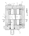
- Figure 1 is an axial sectional view of a hydraulic pump standard gear.
- Figure 2 is a sectional view along the line II-II of Figure 1, more large scale.
- the improved hydraulic gear pump according to the invention has the standard structure known per se as shown in Figures 1 and 2.
- These pumps essentially comprise a housing or casing 1 formed by a body central 2 and front and rear bodies 3 and 4 respectively which define a substantially cylindrical internal space in which two are mounted pinions meshing with each other, namely a driving pinion 6 driven in rotation by a drive shaft 7 and a driven pinion 8.
- the pinions are carried by front and rear bearings indicated at 10 and 11 respectively.
- the drawing further shows at 12 the assembly tie rods of the casing.
- the latter has a suction path 13 of a hydraulic fluid and a discharge path 14 of pressurized fluid.
- the particularity of the present invention resides in the fact that at least one of the pinions 6, 8, namely in particular the driven pinion 8, is produced in a material having in addition appropriate mechanical properties, namely a good resistance to wear and friction, damping properties vibrations induced in the pinion.
- a particularly suitable material is formed from polymers or copolymers advantageously modified by carbon loads. But any other material that has both properties above can be used.
- the material of the led gear could be semi-crystalline aromatic linear polymer marketed under the name PEEK.
- a gear in polymer material, in accordance with the present invention can be manufactured by injection into a mold, which makes it possible to manufacture the pinion a low cost price.
- the use of the polymer material in reducing the noise level extends the possible speed range of the pump.
- the pump, rotating faster has a smaller displacement and is therefore less bulky, on the one hand, and at a price on the other hand, due to the gain in material. In this advantage adds a lighter weight.
Landscapes
- Engineering & Computer Science (AREA)
- Mechanical Engineering (AREA)
- General Engineering & Computer Science (AREA)
- Rotary Pumps (AREA)
- Details And Applications Of Rotary Liquid Pumps (AREA)
Abstract
Description
Claims (6)
- Pompe hydraulique à engrenage du type comprenant un pignon menant et un pignon mené engrenant l'un l'autre dans un carter comportant un canal d'aspiration et un canal de refoulement d'un fluide hydraulique, caractérisée en ce qu'au moins un des pignons (6, 8) est réalisé en un matériau ayant, en plus des propriétés de résistance mécanique, des propriétés d'amortissement de vibrations.
- Pompe selon la revendication 1, caractérisée en ce le matériau constitutif dudit pignon (6, 8) possède un coefficient de frottement relativement faible.
- Pompe selon la revendication 2, caractérisée en ce qu'au moins le pignon mené (8) est réalisé en le matériau à faible coefficient de frottement ayant des propriétés d'amortissement de vibrations.
- Pompe selon l'une des revendications 1 à 3, caractérisée en ce que le matériau constitutif du pignon est un matériau polymère ou copolymère, le cas échéant modifié par des charges de carbone.
- Pompe selon la revendication 4, caractérisée en ce que le matériau polymère est un polymère linéaire aromatique semi-cristallin tel que le matériau commercialisé sous le nom PEEK.
- Pompe selon l'une des revendications précédentes, caractérisée en ce que le pignon (6, 8) est susceptible d'être fabriqué par injection.
Applications Claiming Priority (2)
| Application Number | Priority Date | Filing Date | Title |
|---|---|---|---|
| FR9906801A FR2794188B1 (fr) | 1999-05-28 | 1999-05-28 | Pompe hydraulique a engrenage |
| FR9906801 | 1999-05-28 |
Publications (2)
| Publication Number | Publication Date |
|---|---|
| EP1055819A1 true EP1055819A1 (fr) | 2000-11-29 |
| EP1055819B1 EP1055819B1 (fr) | 2007-10-24 |
Family
ID=9546148
Family Applications (1)
| Application Number | Title | Priority Date | Filing Date |
|---|---|---|---|
| EP20000401476 Expired - Lifetime EP1055819B1 (fr) | 1999-05-28 | 2000-05-25 | Pompe hydraulique à engrenage |
Country Status (3)
| Country | Link |
|---|---|
| EP (1) | EP1055819B1 (fr) |
| DE (1) | DE60036833T2 (fr) |
| FR (1) | FR2794188B1 (fr) |
Cited By (2)
| Publication number | Priority date | Publication date | Assignee | Title |
|---|---|---|---|---|
| WO2007028429A1 (fr) * | 2005-09-02 | 2007-03-15 | Fresenius Medical Care Deutschland Gmbh | Pompe a engrenages |
| WO2019211540A1 (fr) | 2018-05-04 | 2019-11-07 | Exoes | Pompe a engrenages pour la circulation d'un fluide |
Citations (7)
| Publication number | Priority date | Publication date | Assignee | Title |
|---|---|---|---|---|
| JPS57151087A (en) * | 1981-03-12 | 1982-09-18 | Matsushita Electric Ind Co Ltd | Gear pump |
| US4583924A (en) * | 1983-11-10 | 1986-04-22 | Fresenius Ag | Gear pump, especially for medical purposes |
| US5163824A (en) * | 1990-04-23 | 1992-11-17 | Transcience Associates Inc. | Rubber-geared pump with shaftless gear |
| JPH08247246A (ja) * | 1995-01-11 | 1996-09-24 | Mitsubishi Heavy Ind Ltd | 搬送用ラックピニオンの潤滑装置 |
| JPH1028930A (ja) * | 1996-07-15 | 1998-02-03 | Nkk Corp | 樹脂被覆金属体 |
| JPH1077974A (ja) * | 1996-09-03 | 1998-03-24 | Heishin Sobi Kk | 一軸偏心ねじポンプ |
| US5865239A (en) * | 1997-02-05 | 1999-02-02 | Micropump, Inc. | Method for making herringbone gears |
-
1999
- 1999-05-28 FR FR9906801A patent/FR2794188B1/fr not_active Expired - Lifetime
-
2000
- 2000-05-25 EP EP20000401476 patent/EP1055819B1/fr not_active Expired - Lifetime
- 2000-05-25 DE DE2000636833 patent/DE60036833T2/de not_active Expired - Lifetime
Patent Citations (7)
| Publication number | Priority date | Publication date | Assignee | Title |
|---|---|---|---|---|
| JPS57151087A (en) * | 1981-03-12 | 1982-09-18 | Matsushita Electric Ind Co Ltd | Gear pump |
| US4583924A (en) * | 1983-11-10 | 1986-04-22 | Fresenius Ag | Gear pump, especially for medical purposes |
| US5163824A (en) * | 1990-04-23 | 1992-11-17 | Transcience Associates Inc. | Rubber-geared pump with shaftless gear |
| JPH08247246A (ja) * | 1995-01-11 | 1996-09-24 | Mitsubishi Heavy Ind Ltd | 搬送用ラックピニオンの潤滑装置 |
| JPH1028930A (ja) * | 1996-07-15 | 1998-02-03 | Nkk Corp | 樹脂被覆金属体 |
| JPH1077974A (ja) * | 1996-09-03 | 1998-03-24 | Heishin Sobi Kk | 一軸偏心ねじポンプ |
| US5865239A (en) * | 1997-02-05 | 1999-02-02 | Micropump, Inc. | Method for making herringbone gears |
Non-Patent Citations (4)
| Title |
|---|
| PATENT ABSTRACTS OF JAPAN vol. 006, no. 256 (M - 179) 15 December 1982 (1982-12-15) * |
| PATENT ABSTRACTS OF JAPAN vol. 1997, no. 01 31 January 1997 (1997-01-31) * |
| PATENT ABSTRACTS OF JAPAN vol. 1998, no. 06 30 April 1998 (1998-04-30) * |
| PATENT ABSTRACTS OF JAPAN vol. 1998, no. 08 30 June 1998 (1998-06-30) * |
Cited By (3)
| Publication number | Priority date | Publication date | Assignee | Title |
|---|---|---|---|---|
| WO2007028429A1 (fr) * | 2005-09-02 | 2007-03-15 | Fresenius Medical Care Deutschland Gmbh | Pompe a engrenages |
| WO2019211540A1 (fr) | 2018-05-04 | 2019-11-07 | Exoes | Pompe a engrenages pour la circulation d'un fluide |
| FR3080892A1 (fr) * | 2018-05-04 | 2019-11-08 | Exoes | Pompe a engrenages pour la circulation d’un fluide |
Also Published As
| Publication number | Publication date |
|---|---|
| FR2794188A1 (fr) | 2000-12-01 |
| DE60036833D1 (de) | 2007-12-06 |
| DE60036833T2 (de) | 2008-07-31 |
| FR2794188B1 (fr) | 2001-08-10 |
| EP1055819B1 (fr) | 2007-10-24 |
Similar Documents
| Publication | Publication Date | Title |
|---|---|---|
| FR2677414A1 (fr) | Moteur equipe d'un mecanisme reducteur a vis. | |
| FR2495713A1 (fr) | Dispositif pour absorber des vibrations de torsion | |
| EP2281107B1 (fr) | Moteur pourvu d'une chambre a volume variable | |
| FR2856440A1 (fr) | Compresseur de turbomachine et roue dudit compresseur | |
| EP1759125B1 (fr) | Dispositif de guidage d'un arbre en mouvement oscillant | |
| EP0051605A1 (fr) | Amplificateur de puissance pour moteurs thermiques ou autres | |
| FR2881189A1 (fr) | Pompe a vide a cycle de translation circulaire a plusieurs arbres | |
| EP1055819B1 (fr) | Pompe hydraulique à engrenage | |
| FR2808465A1 (fr) | Systeme de refroidissement pour un outil de travail manoeuvre a la main | |
| FR2749045A1 (fr) | Compresseur, notamment pour des systemes de climatisation dans des vehicules | |
| EP3973158A1 (fr) | Agencement de turbomachines d'aeronautique comprenant une pompe de lubrification entrainee par deux engrenages obliques | |
| FR2657122A1 (fr) | Pompe a essence pour systemes d'injection de moteurs a explosion. | |
| CA3078596A1 (fr) | Dispositif de forme spherique et muni de cannelures bombees pour former une liaison rotule a doigt, et pompe a barillet muni d'un tel dispositif | |
| FR2830905A1 (fr) | Pompe a vide | |
| FR2837773A1 (fr) | Appareil de direction du vehicule | |
| FR2663012A1 (fr) | Secoueur a engrenages non metalliques. | |
| BE1005111A3 (fr) | Dispositif de preparation, sous forme de charges, d'un produit en vrac. | |
| FR3055119A1 (fr) | Entrainement d'essuie-glace | |
| EP4638981A1 (fr) | Ensemble de transmission de couple pour un appareil de mobilite | |
| FR3026793B1 (fr) | Machine hydraulique comprenant des bossages de fixation allonges pour reduire le bruit | |
| FR3075277A1 (fr) | Pompe hydraulique a spheres serties | |
| FR2995016A1 (fr) | Turbocompresseur de gaz d'echappement | |
| EP1608893B1 (fr) | Poulie, dispositif de detection comprenant une telle poulie, et moteur a combustion interne equipe d'un tel dispositif | |
| FR2547551A1 (fr) | Reducteur de vitesse pour moteur d'aviation | |
| EP0645555B1 (fr) | Amortisseur pour engrenage mené par un moteur pas-à-pas |
Legal Events
| Date | Code | Title | Description |
|---|---|---|---|
| PUAI | Public reference made under article 153(3) epc to a published international application that has entered the european phase |
Free format text: ORIGINAL CODE: 0009012 |
|
| AK | Designated contracting states |
Kind code of ref document: A1 Designated state(s): DE GB IT SE |
|
| AX | Request for extension of the european patent |
Free format text: AL;LT;LV;MK;RO;SI |
|
| 17P | Request for examination filed |
Effective date: 20010523 |
|
| AKX | Designation fees paid |
Free format text: DE GB IT SE |
|
| 17Q | First examination report despatched |
Effective date: 20050307 |
|
| GRAP | Despatch of communication of intention to grant a patent |
Free format text: ORIGINAL CODE: EPIDOSNIGR1 |
|
| GRAS | Grant fee paid |
Free format text: ORIGINAL CODE: EPIDOSNIGR3 |
|
| GRAA | (expected) grant |
Free format text: ORIGINAL CODE: 0009210 |
|
| AK | Designated contracting states |
Kind code of ref document: B1 Designated state(s): DE GB IT SE |
|
| REG | Reference to a national code |
Ref country code: GB Ref legal event code: FG4D Free format text: NOT ENGLISH |
|
| REF | Corresponds to: |
Ref document number: 60036833 Country of ref document: DE Date of ref document: 20071206 Kind code of ref document: P |
|
| REG | Reference to a national code |
Ref country code: SE Ref legal event code: TRGR |
|
| GBT | Gb: translation of ep patent filed (gb section 77(6)(a)/1977) |
Effective date: 20080131 |
|
| PLBE | No opposition filed within time limit |
Free format text: ORIGINAL CODE: 0009261 |
|
| STAA | Information on the status of an ep patent application or granted ep patent |
Free format text: STATUS: NO OPPOSITION FILED WITHIN TIME LIMIT |
|
| 26N | No opposition filed |
Effective date: 20080725 |
|
| PGFP | Annual fee paid to national office [announced via postgrant information from national office to epo] |
Ref country code: IT Payment date: 20190529 Year of fee payment: 20 |
|
| PGFP | Annual fee paid to national office [announced via postgrant information from national office to epo] |
Ref country code: SE Payment date: 20190527 Year of fee payment: 20 |
|
| PGFP | Annual fee paid to national office [announced via postgrant information from national office to epo] |
Ref country code: DE Payment date: 20190731 Year of fee payment: 20 Ref country code: GB Payment date: 20190529 Year of fee payment: 20 |
|
| REG | Reference to a national code |
Ref country code: DE Ref legal event code: R071 Ref document number: 60036833 Country of ref document: DE |
|
| REG | Reference to a national code |
Ref country code: GB Ref legal event code: PE20 Expiry date: 20200524 |
|
| REG | Reference to a national code |
Ref country code: SE Ref legal event code: EUG |
|
| PG25 | Lapsed in a contracting state [announced via postgrant information from national office to epo] |
Ref country code: GB Free format text: LAPSE BECAUSE OF EXPIRATION OF PROTECTION Effective date: 20200524 |