EP1055364A1 - Window box arrangement obtained by rotational moulding - Google Patents
Window box arrangement obtained by rotational moulding Download PDFInfo
- Publication number
- EP1055364A1 EP1055364A1 EP00440152A EP00440152A EP1055364A1 EP 1055364 A1 EP1055364 A1 EP 1055364A1 EP 00440152 A EP00440152 A EP 00440152A EP 00440152 A EP00440152 A EP 00440152A EP 1055364 A1 EP1055364 A1 EP 1055364A1
- Authority
- EP
- European Patent Office
- Prior art keywords
- wall
- water
- planter
- level
- certain distance
- Prior art date
- Legal status (The legal status is an assumption and is not a legal conclusion. Google has not performed a legal analysis and makes no representation as to the accuracy of the status listed.)
- Granted
Links
Images
Classifications
-
- A—HUMAN NECESSITIES
- A01—AGRICULTURE; FORESTRY; ANIMAL HUSBANDRY; HUNTING; TRAPPING; FISHING
- A01G—HORTICULTURE; CULTIVATION OF VEGETABLES, FLOWERS, RICE, FRUIT, VINES, HOPS OR SEAWEED; FORESTRY; WATERING
- A01G27/00—Self-acting watering devices, e.g. for flower-pots
- A01G27/04—Self-acting watering devices, e.g. for flower-pots using wicks or the like
Definitions
- the invention relates to a planter device obtained by rotational molding and defined by a hollow body delimited by an envelope comprising two section walls, substantially, in ⁇ U ⁇ and each delimited by a bottom, said walls being arranged, on the one hand, one inside the other and, on the other hand, at a certain distance from each other, while the bottom of the wall external is located opposite and at a certain distance from the bottom of the internal wall, the latter defining a tank intended to receive of earth while the external wall constitutes a water reserve whose upper level is located at a certain distance from the bottom of the inner wall.
- the present invention relates to the field of the manufacture of planters in synthetic material obtained by the technique of rotational molding.
- Such a planter is, then, constituted by a hollow body delimited by an envelope comprising an internal wall suitable for define a tank intended to contain this earth.
- a bin presents, usually a bottom closed so that, generally, a excess water likely to stagnate in this tank even when the earth seems dehydrated, at least on the surface. Such stagnation may wet the earth too much and, as a result, cause rot plants.
- This planter has, at its internal wall, an orifice for filling the water reserve.
- an orifice for filling the water reserve.
- the bottom of the inner wall has a well extending direction of the bottom of the outer wall and receiving a wick or analog extending in the earth tank.
- the bottom of this well has at least one orifice capable of authorizing the passage of the water inside said well for its routing in the tank to earth through said wick.
- this well is constantly submerged in the reserve water, at least at least level of its bottom provided with the opening (s). It follows that it does not there may be no air circulation, through this well, between, on the one hand, the internal volume of the earth tank and, on the other share, the internal volume delimited by the external wall. So the particular design of this planter does not allow, we automatic watering position, to ensure oxygenation of the soil contained in the soil container. This lack of oxygenation leads root rot of contained plants or the like in the earthen bin.
- the present invention overcomes the disadvantages of state-of-the-art planters.
- the present invention relates to a device for planter obtained by rotational molding and defined by a hollow body delimited by an envelope comprising two section walls, substantially, in ⁇ U ⁇ and delimited, each by a bottom, said walls being arranged, on the one hand, one inside the other and, on the other hand, at a certain distance from each other, while that the bottom of the outer wall is located opposite and at a certain distance from the bottom of the inner wall, the latter defining a tray intended to receive soil while the outer wall constitutes a water reserve the upper level of which is located certain distance from the bottom of the internal wall, characterized by causes the outer wall to have at least one opening for allow the water supply to the water reserve while the internal wall has, at its bottom, at least one chimney protruding towards the inside of the earth tank and the wall of which device is pierced with at least one orifice capable of being traversed by a wick, on the one hand, extending inside the earth tank and, on the other hand, diving into the water reserve.
- the external wall is completed by means capable of defining said upper level of water in constituting an overflow for the evacuation of its excess.
- An additional characteristic concerns the fact that the means able to define said upper level of water are constituted by at least one drainage orifice made in said external wall and located, below the level of the bottom of the internal wall, at a certain distance from this background.
- such means capable of defining said upper water level consist of at least one water supply opening located, at least in part, under the level of the bottom of the inner wall and at a certain distance from it background.
- An additional characteristic relates to the fact that said opening results from a removal of material operated at the outer wall of the planter, after its rotational molding.
- this opening is delimited by a portion of said outer wall having been indexed, weakened and / or precut.
- planter has, in its lower part and at the level of its wall external, a peripheral outgrowth extending at the level of one at least on the sides of said external wall and comprising, on the above, at least one water supply opening.
- this peripheral outgrowth has dimensions, overall, significantly higher than those of the outer wall of the planter so as to spare, when two planters are juxtaposed, sufficient space between them to ensure the filling their water reserves.
- peripheral outgrowth extends around the entire periphery of said outer wall and adopts, substantially, the shape of a cup, a saucer or the like similar to that intended to supplement a terracotta planter.
- the advantages of the present invention relate to the fact that the internal volume of the hollow body of a planter obtained by rotational molding is used to build up a water reserve independent of a container intended to contain the earth.
- the supply of water to level of the latter is achieved through humidification necessary and sufficient provided by means of a wick able, on the one hand, to soak in water and, on the other hand, to spread In the ground.
- the arrangement of the water supply openings and / or drainage holes make it possible to constitute an overflow drain of water and to impose, on the latter, a higher level located at a certain distance from the bottom of the ground tank. This avoids this last to be in direct contact with water and preserves the plants of any rotting.
- the difference in level between the water and the bottom of the earth allows air circulation which advantageously allows to ventilate this earth.
- the present invention relates to the field of the manufacture of planters obtained from a synthetic material and by the rotational molding technique.
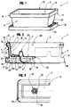
- Such a planter 1 is, in fact, defined by a hollow body 2 having an internal volume 3 delimited by an envelope 4.
- the latter is in the form of two walls 5, 6 of section substantially in ⁇ U ⁇ and delimited, each and respectively, by a bottom 7, 8 and side walls 9, 10.
- the walls 5 and 6 of this envelope 4 are arranged, on the one hand, one 5 inside the other 6 so as to define a wall internal 5 and an external wall 6 and, on the other hand, so their bottoms 7 and 8 are facing each other.
- the continuity of the casing slat 4, between the internal walls 5 and external 6, is provided, at least, in the upper part 11 of said planter 1 and via an upper rim 12 capable of connect the upper end of the side walls 9 and 10 of these two walls 5 and 6.
- This upper edge 12 is defined during rotational molding and extends to the upper edge 13 of the planter slat 1, on the entire periphery 14 of the latter.
- said internal walls 5 and external 6 have, between them, a spacing 15 and are located, therefore at a distance 16 from one another 5 from 6 so as to delimit the internal volume 3 of said hollow body 2.
- the bottom 7 of the internal wall 5 is located at a certain distance 16 'from the bottom 8 of the external wall 6.
- the latter 5 in fact defines a tray 20 intended to receive the earth and has, at its bottom 8, at least one orifice 21 suitable for being crossed by a wick 22.
- the latter is intended, in part, to dive into said water reserve 17, at less through one 23 of its ends 23, 24, this wick 22 passing through said orifice 21 to come extend, in part, in said tray 20. It is in the latter that said wick 22 comes to be intimately incorporated into the earth for its moistening, by capillarity.
- said external wall 6 also comprises at least an opening 25 for supplying water to said reserve 17.
- the external wall 6 is completed by means 26 capable of defining said upper level 18 of the water reserve 17.
- Such means 26 constitute, in fact, an overflow for the evacuation of water in excess so as to prevent this water from rising in the tank 20 to Earth.
- a first solution consists in sparing, at the level of the external wall 6, at least one drainage orifice, this the latter being located under level 27 of the bottom 7 of the internal wall 5, and at a certain distance 19 from this bottom 7.
- such means 26 are constituted by at least one opening 25 water supply. This opening 25 is then, at least in part, located under level 27 of the bottom 7 of the internal wall 5, and at a certain distance 19 from this bottom 7.
- this opening 25 can be defined, directly, during rotational molding.
- this opening 25 results from a withdrawal of material operated at the level of the external wall 6 of the planter 1, after rotational molding of the latter.
- such an opening 25 can be delimited by a portion 28 of said outer wall 6 at which the latter has been indexed, weakened and / or precut to facilitate such removal of material.
- the pre-cutting of the portion 28 can, for example, be defined under the form of dotted lines constituting a starting point for said break outer wall 6.
- such an opening 25 can, still, be defined by a retractable portion of said wall external 6.
- said planter 1 has, in its lower part 29 and at the level of its outer wall 6, a peripheral projection 30 extending at level of at least one of the sides of said external wall 6.
- Such a protrusion 30 has, on top 31, at least one water supply opening 25 or at least a portion 28 outer wall 6 intended to be removed.
- a such protuberance 30 has dimensions, overall, significantly higher than those of the outer wall 6 of the planter 1. Such an embodiment allows, when two planters 1 are juxtaposed, to provide sufficient space between these to allow access to opening 25 and, thus, allow the filling of water reserves 17.
- such an outgrowth peripheral 30 extends over the entire periphery of said external wall 6 and adopts, appreciably, the shape of a cup, of a tray, a saucer or the like similar to that intended to supplement a terracotta planter.
- An additional feature of the present invention relates to the fact that the bottom 7 of the internal wall 5 comprises at least one chimney 32 projecting towards the inside of the earth tank.
- a such chimney 32 has a peripheral wall 33 comprising at minus one orifice 34 for the passage of the wick 22.
- Such an orifice 34 can, according to a preferred embodiment and at like opening 25, be defined by a portion of wall internal 5 able to be removed, after rotational molding of the planter 1.
- an orifice 34 may still allow passage air through the internal wall 5 in order to ensure a aeration of the soil contained in the tank 20.
- a channel 35 is defined at inside which is likely to establish a circulation air enters, on the one hand, the opening (s) 25 and, on the other hand, the orifice (s) 34.
Abstract
Description
L'invention concerne un dispositif de jardinière obtenue par rotomoulage et définie par un corps creux délimité par une enveloppe comportant deux parois de section, sensiblement, en 〈〈 U 〉〉 et délimitées, chacune, par un fond, lesdites parois étant disposées, d'une part, l'une à l'intérieur de l'autre et, d'autre part, à une certaine distance l'une de l'autre, tandis que le fond de la paroi externe se situe en regard et à une certaine distance du fond de la paroi interne, cette dernière définissant un bac destiné à recevoir de la terre tandis que la paroi externe constitue une réserve d'eau dont le niveau supérieur se situe à une certaine distance du fond de la paroi interne.The invention relates to a planter device obtained by rotational molding and defined by a hollow body delimited by an envelope comprising two section walls, substantially, in 〈〈 U 〉〉 and each delimited by a bottom, said walls being arranged, on the one hand, one inside the other and, on the other hand, at a certain distance from each other, while the bottom of the wall external is located opposite and at a certain distance from the bottom of the internal wall, the latter defining a tank intended to receive of earth while the external wall constitutes a water reserve whose upper level is located at a certain distance from the bottom of the inner wall.
La présente invention concerne le domaine de la fabrication de jardinières en matériau synthétique obtenues par la technique du rotomoulage.The present invention relates to the field of the manufacture of planters in synthetic material obtained by the technique of rotational molding.
L'on connaít, d'ores et déjà, un certain nombre de jardinières destinées à contenir de la terre ou analogue dans laquelle vont être plantés des végétaux tels que des plantes vertes, des légumes ou autres.We already know a number of planters intended to contain soil or the like in which are going to be planted plants such as green plants, vegetables or other.
Une telle jardinière est, alors, constituée par un corps creux délimité par une enveloppe comportant une paroi interne apte à définir un bac destiné à contenir cette terre. Un tel bac présente, usuellement, un fond fermé de sorte qu'il subsiste, généralement, un excédent d' eau susceptible de stagner dans ce bac alors même que la terre semble déshydratée, du moins en surface. Une telle stagnation risque de trop mouiller la terre et, de ce fait, de faire pourrir les plantes.Such a planter is, then, constituted by a hollow body delimited by an envelope comprising an internal wall suitable for define a tank intended to contain this earth. Such a bin presents, usually a bottom closed so that, generally, a excess water likely to stagnate in this tank even when the earth seems dehydrated, at least on the surface. Such stagnation may wet the earth too much and, as a result, cause rot plants.
Il est, également, connu au travers du document DE 85 25 768 U une jardinière obtenue par rotomoulage et définie par un corps creux délimité par une enveloppe comportant deux parois de section, sensiblement, on 〈〈 13 〉〉 et délimitées, chacune, par un fond, lesdits fonds se situant en regard et à une certaine distance l'un de l'autre. Ces parois sont disposées, d'une part, l'une à l'intérieur de l'autre et, d'autre part, à une certaine distance l'une de l'autre. La paroi interne définit un bac destiné à recevoir de la terre tandis que la paroi externe constitue une réserve d'eau dont le niveau supérieur se situe à une certaine distance du fond de la paroi interne.It is also known from document DE 85 25 768 U a planter obtained by rotational molding and defined by a hollow body delimited by an envelope comprising two section walls, substantially, one 〈〈 13 〉〉 and delimited, each one, by a bottom, said funds lying opposite and at a certain distance one of the other. These walls are arranged, on the one hand, one inside on the other and, on the other hand, at a certain distance one of the other. The internal wall defines a tank intended to receive earth while the external wall constitutes a water reserve of which the upper level is located some distance from the bottom of the inner wall.
Cette jardinière comporte, au niveau de sa paroi interne, un orifice pour le remplissage de la réserve d'eau. A ce propos, on observera que, lorsque la jardinière contient des plantes ou analogue, il est particulièrement difficile d'accéder à cet orifice et, par conséquent, d'assurer le remplissage de ladite réserve d'eau.This planter has, at its internal wall, an orifice for filling the water reserve. In this regard, we will observe that when the planter contains plants or the like it is particularly difficult to access this orifice and, by Therefore, to ensure the filling of said water reserve.
De plus, le fond de la paroi interne présente un puits s'étendant on direction du fond de la paroi externe et recevant une mèche ou analogue s' étendant dans le bac à terre. On observera que le fond de ce puits comporte au moins un orifice apte à autoriser le passage de l'eau à l'intérieur dudit puits pour son acheminement dans le bac à terre par l'intermédiaire de ladite mèche. Aussi, pour permettre un pompage de l'eau par la mèche, il est indispensable que ce puits soit constamment immergé dans l'eau de la réserve, au moins au niveau de son fond pourvu du ou des orifices. Il on résulte qu'il ne peut y avoir aucune circulation d'air, au travers de ce puits, entre, d'une part, le volume interne du bac à terre et, d'autre part, le volume interne délimité par la paroi externe. Ainsi, la conception particulière de cette jardinière ne permet aucunement, on position d'arrosage automatique, d'assurer une oxygénation de la terre contenue dans la bac à terre. Ce défaut d'oxygénation conduit à un pourrissement des racines des plantes ou analogue contenues dans le bac à terre.In addition, the bottom of the inner wall has a well extending direction of the bottom of the outer wall and receiving a wick or analog extending in the earth tank. We will observe that the bottom of this well has at least one orifice capable of authorizing the passage of the water inside said well for its routing in the tank to earth through said wick. Also, to allow a pumping water through the wick, it is essential that this well is constantly submerged in the reserve water, at least at least level of its bottom provided with the opening (s). It follows that it does not there may be no air circulation, through this well, between, on the one hand, the internal volume of the earth tank and, on the other share, the internal volume delimited by the external wall. So the particular design of this planter does not allow, we automatic watering position, to ensure oxygenation of the soil contained in the soil container. This lack of oxygenation leads root rot of contained plants or the like in the earthen bin.
La présente invention permet de remédier aux inconvénients des jardinières de l'état de la technique. The present invention overcomes the disadvantages of state-of-the-art planters.
A cet effet, la présente invention concerne un dispositif de jardinière obtenue par rotomoulage et définie par un corps creux délimité par une enveloppe comportant deux parois de section, sensiblement, en 〈〈 U〉〉 et délimitées, chacune, par un fond, lesdites parois étant disposées, d'une part, l'une à l'intérieur de l'autre et, d'autre part, à une certaine distance l'une de l'autre, tandis que le fond de la paroi externe se situe en regard et à une certaine distance du fond de la paroi interne, cette dernière définissant un bac destiné à recevoir de la terre tandis que la paroi externe constitue une réserve d'eau dont le niveau supérieur se situe à une certaine distance du fond de la paroi interne, caractérisé par le fait que la paroi externe comporte au moins une ouverture destinée à permettre l'alimentation en eau de la réserve d'eau tandis que la paroi interne comporte, au niveau de son fond, au moins une cheminée faisant saillie vers l'intérieur du bac à terre et dont la paroi périphérique est percée d'au moins un orifice apte à être traversé par une mèche, d'une part, s'étendant à l'intérieur du bac à terre et, d'autre part, plongeant dans la réserve d'eau.To this end, the present invention relates to a device for planter obtained by rotational molding and defined by a hollow body delimited by an envelope comprising two section walls, substantially, in 〈〈 U 〉〉 and delimited, each by a bottom, said walls being arranged, on the one hand, one inside the other and, on the other hand, at a certain distance from each other, while that the bottom of the outer wall is located opposite and at a certain distance from the bottom of the inner wall, the latter defining a tray intended to receive soil while the outer wall constitutes a water reserve the upper level of which is located certain distance from the bottom of the internal wall, characterized by causes the outer wall to have at least one opening for allow the water supply to the water reserve while the internal wall has, at its bottom, at least one chimney protruding towards the inside of the earth tank and the wall of which device is pierced with at least one orifice capable of being traversed by a wick, on the one hand, extending inside the earth tank and, on the other hand, diving into the water reserve.
Selon une autre caractéristique, la paroi externe est complétée par des moyens aptes à définir ledit niveau supérieur de l'eau en constituant un trop plein pour l'évacuation de son excès.According to another characteristic, the external wall is completed by means capable of defining said upper level of water in constituting an overflow for the evacuation of its excess.
Une caractéristique additionnelle concerne le fait que les moyens aptes à définir ledit niveau supérieur de l'eau sont constitués par au moins un orifice de drainage pratiqué dans ladite paroi externe et situé, sous le niveau du fond de la paroi interne, à une certaine distance de ce fond.An additional characteristic concerns the fact that the means able to define said upper level of water are constituted by at least one drainage orifice made in said external wall and located, below the level of the bottom of the internal wall, at a certain distance from this background.
Selon une autre caractéristique, de tels moyens aptes à définir ledit niveau supérieur de l'eau sont constitués par au moins une ouverture d'alimentation en eau située, au moins en partie, sous le niveau du fond de la paroi interne et à une certaine distance de ce fond. According to another characteristic, such means capable of defining said upper water level consist of at least one water supply opening located, at least in part, under the level of the bottom of the inner wall and at a certain distance from it background.
Une caractéristique additionnelle est relative au fait que ladite ouverture résulte d'un retrait de matière opéré au niveau de la paroi externe de la jardinière, après son rotomoulage.An additional characteristic relates to the fact that said opening results from a removal of material operated at the outer wall of the planter, after its rotational molding.
Selon une autre caractéristique, cette ouverture est délimitée par une portion de ladite paroi externe ayant été indexée, fragilisée et/ou prédécoupée.According to another characteristic, this opening is delimited by a portion of said outer wall having been indexed, weakened and / or precut.
Une autre caractéristique concerne le fait que ladite jardinière comporte, dans sa partie inférieure et au niveau de sa paroi externe, une excroissance périphérique s'étendant au niveau de l'un au moins des cotés de ladite paroi externe et comportant, sur le dessus, au moins une ouverture d'alimentation en eau.Another characteristic concerns the fact that said planter has, in its lower part and at the level of its wall external, a peripheral outgrowth extending at the level of one at least on the sides of said external wall and comprising, on the above, at least one water supply opening.
En fait, cette excroissance périphérique présente des dimensions, hors tout, sensiblement supérieures à celles de la paroi externe de la jardinière de manière à ménager, lorsque deux jardinières sont juxtaposées, un espace suffisant entre ces dernières pour assurer le remplissage de leurs réserves d'eau.In fact, this peripheral outgrowth has dimensions, overall, significantly higher than those of the outer wall of the planter so as to spare, when two planters are juxtaposed, sufficient space between them to ensure the filling their water reserves.
Une caractéristique additionnelle concerne le fait que ladite excroissance périphérique s'étend sur tout le pourtour de ladite paroi externe et adopte, sensiblement, la forme d'une coupelle, d'une soucoupe ou analogue similaire à celle destinée à compléter une jardinière en terre cuite.An additional characteristic concerns the fact that said peripheral outgrowth extends around the entire periphery of said outer wall and adopts, substantially, the shape of a cup, a saucer or the like similar to that intended to supplement a terracotta planter.
Les avantages de la présente invention concernent le fait que le volume interne du corps creux d'une jardinière obtenue par rotomoulage est mis à profit pour constituer une réserve d'eau indépendante d'un bac destiné à contenir la terre. L'apport d'eau au niveau de cette dernière est réalisé au travers d'une humidification nécessaire et suffisante assurée par l'intermédiaire d'une mèche apte, d'une part, à tremper dans l'eau et, d'autre part, à s'étendre dans la terre. The advantages of the present invention relate to the fact that the internal volume of the hollow body of a planter obtained by rotational molding is used to build up a water reserve independent of a container intended to contain the earth. The supply of water to level of the latter is achieved through humidification necessary and sufficient provided by means of a wick able, on the one hand, to soak in water and, on the other hand, to spread In the ground.
La disposition des ouvertures d'alimentation en eau et/ou des orifices de drainage permet de constituer un trop plein d'évacuation d'eau et d'imposer, à cette dernière, un niveau supérieur situé à une certaine distance du fond du bac à terre. Ceci évite à cette dernière d'être en contact direct avec l'eau et préserve les végétaux de tout pourrissement.The arrangement of the water supply openings and / or drainage holes make it possible to constitute an overflow drain of water and to impose, on the latter, a higher level located at a certain distance from the bottom of the ground tank. This avoids this last to be in direct contact with water and preserves the plants of any rotting.
De plus, la différence de niveau entre l'eau et le fond du bac à terre autorise une circulation d'air ce qui permet, avantageusement, d'aérer cette terre.In addition, the difference in level between the water and the bottom of the earth allows air circulation which advantageously allows to ventilate this earth.
L'invention est exposée plus en détail dans la description qui va suivre se rapportant à des modes de réalisation qui ne sont donnés qu'à titre d'exemples indicatifs et non limitatifs.The invention is explained in more detail in the description which follows follow pertaining to embodiments that are not given as examples only and not limiting.
La compréhension de cette description sera facilitée en se référant
au dessin joint en annexe et dans lequel :
La présente invention concerne le domaine de la fabrication de jardinières obtenues à partir d'un matériau synthétique et par la technique du rotomoulage.The present invention relates to the field of the manufacture of planters obtained from a synthetic material and by the rotational molding technique.
Une telle jardinière 1 est, en fait, définie par un corps creux 2
présentant un volume interne 3 délimité par une enveloppe 4. Such a planter 1 is, in fact, defined by a
Cette dernière se présente sous la forme de deux parois 5, 6 de
section sensiblement en 〈〈 U〉〉 et délimitées, chacune et
respectivement, par un fond 7, 8 et des parois latérales 9, 10.The latter is in the form of two
Les parois 5 et 6 de cette enveloppe 4 sont disposées, d'une part,
l'une 5 à l'intérieur de l'autre 6 de manière à définir une paroi
interne 5 et une paroi externe 6 et, d'autre part, de telle sorte
que leurs fonds 7 et 8 soient en regard l'un de l'autre.The
Tel que visible, plus particulièrement, sur la figure 2, la
continuité de latte enveloppe 4, entre les parois interne 5 et
externe 6, est assurée, au moins, en partie supérieure 11 de ladite
jardinière 1 et par l'intermédiaire d'un rebord supérieur 12 apte à
relier l'extrémité supérieure des parois latérales 9 et 10 de ces
deux parois 5 et 6. Ce rebord supérieur 12 est défini lors du
rotomoulage et s'étend en bordure supérieure 13 de latte jardinière
1, sur tout le pourtour 14 de cette dernière.As can be seen more particularly in FIG. 2, the
continuity of the casing slat 4, between the
Comme visible sur cette même figure, lesdites parois interne 5 et
externe 6 présentent, entre elles, un espacement 15 et se situent,
par conséquent, à une certaine distance 16 l'une 5 de l'autre 6 de
manière à délimiter le volume interne 3 dudit corps creux 2.As can be seen in this same figure, said
Selon l'invention, le fond 7 de la paroi interne 5 est situé à une
certaine distance 16' du fond 8 de la paroi externe 6.According to the invention, the
L'espacement entre ces deux fonds 7, 8 est mis à profit pour que
ladite paroi externe 6 définisse une réserve d'eau 17. Cette
dernière présente un niveau supérieur 18 se situant à une certaine
distance 19 du fond 7 de la paroi interne 5.The spacing between these two
Cette dernière 5 définit, en fait, un bac 20 destiné à recevoir de
la terre et comporte, au niveau de son fond 8, au moins un orifice
21 apte à être traversé par une mèche 22. Cette dernière est
destinée, en partie, à plonger dans ladite réserve d'eau 17, au
moins au travers de l'une 23 de ses extrémités 23, 24, cette mèche
22 traversant ledit orifice 21 pour venir s'étendre, en partie, dans
ledit bac 20. C'est dans ce dernier que ladite mèche 22 vient à être
intimement incorporé à la terre en vue de son humidification, par
capillarité.The latter 5 in fact defines a
On observera que ladite paroi externe 6 comporte, de plus, au moins
une ouverture 25 destinée à l'alimentation en eau de ladite réserve
17.It will be observed that said
Selon une caractéristique additionnelle de la présente invention, la
paroi externe 6 est complétée par des moyens 26 aptes à définir
ledit niveau supérieur 18 de la réserve d'eau 17. De tels moyens 26
constituent, en fait, un trop plein pour l'évacuation de l'eau en
excès de manière à éviter que cette eau ne remonte dans le bac 20 à
terre.According to an additional characteristic of the present invention, the
Une première solution, non représentée, consiste à ménager, au
niveau de la paroi externe 6, au moins un orifice de drainage, ce
dernier étant situé, sous le niveau 27 du fond 7 de la paroi interne
5, et à une certaine distance 19 de ce fond 7.A first solution, not shown, consists in sparing, at the
level of the
Selon un mode préféré de réalisation de la présente invention, de
tels moyens 26 sont constitués par au moins une ouverture 25
d'alimentation en eau. Cette ouverture 25 est alors, au moins en
partie, située sous le niveau 27 du fond 7 de la paroi interne 5, et
à une certaine distance 19 de ce fond 7.According to a preferred embodiment of the present invention,
such means 26 are constituted by at least one opening 25
water supply. This opening 25 is then, at least in
part, located under level 27 of the
En ce qui concerne une telle ouverture 25, celle-ci peut être
définie, directement, lors du rotomoulage.
Cependant et selon un mode de réalisation préféré, cette ouverture
25 résulte d'un retrait de matière opéré au niveau de la paroi
externe 6 de la jardinière 1, après rotomoulage de cette dernière. With regard to such an
However and according to a preferred embodiment, this opening 25 results from a withdrawal of material operated at the level of the
En fait, une telle ouverture 25 peut être délimitée par une portion
28 de ladite paroi externe 6 au niveau de laquelle cette dernière a
été indexée, fragilisée et/ou prédécoupée en vue de faciliter un tel
retrait de matière.In fact, such an
En particulier, au travers d'une telle indexation, il est possible de positionner exactement l'emplacement au niveau duquel, après rotomoulage, il doit être pratiqué une ouverture 25 à l'aide d'un outil approprié, notamment une scie, une meule, d'une fraise ou analogue.In particular, through such indexing, it is possible to position exactly the location at which, after rotational molding, an opening 25 must be made using a suitable tool, including a saw, grinding wheel, cutter or similar.
En fragilisant une portion 28 de la paroi externe 6, il suffit, par
exemple, de briser cette dernière pour définir ladite ouverture 25.By weakening a
Le prédécoupage de la portion 28 peut, par exemple, être défini sous
la forme de pointillés constituant une amorce de rupture de ladite
paroi externe 6.The pre-cutting of the
Selon une autre caractéristique, une telle ouverture 25 peut,
encore, être définie par une portion escamotable de ladite paroi
externe 6.According to another characteristic, such an
Tel que visible sur les figures 1 et 2 du dessin en annexe, ladite
jardinière 1 comporte, dans sa partie inférieure 29 et au niveau de
sa paroi externe 6, une excroissance périphérique 30 s'étendant au
niveau de l'un au moins des cotés de ladite paroi externe 6.As shown in Figures 1 and 2 of the accompanying drawing, said
planter 1 has, in its
Une telle excroissance 30 présente, sur le dessus 31, au moins une
ouverture 25 d'alimentation en eau ou, tout du moins, une portion 28
de paroi externe 6 destinée à être retirée.Such a
En fait et tel que visible, notamment, sur les figures 2 et 3, une
telle excroissance 30 présente des dimensions, hors tout,
sensiblement supérieures à celles de la paroi externe 6 de la
jardinière 1. Un tel mode de réalisation permet, lorsque deux
jardinières 1 sont juxtaposées, de ménager un espace suffisant entre
celles-ci pour autoriser un accès à l'ouverture 25 et, ainsi,
permettre le remplissage des réserves 17 d'eau.In fact and as visible, in particular, in FIGS. 2 and 3, a
Selon un mode de réalisation préféré, une telle excroissance
périphérique 30 s'étend sur tout le pourtour de ladite paroi externe
6 et adopte, sensiblement, la forme d'une coupelle, d'un plateau,
d'une soucoupe ou analogue similaire à celle destinée à compléter
une jardinière en terre cuite.According to a preferred embodiment, such an outgrowth
peripheral 30 extends over the entire periphery of said
Une caractéristique additionnelle de la présente invention concerne
le fait que le fond 7 de la paroi interne 5 comporte au moins une
cheminée 32 faisant saillie vers l'intérieur du bac à terre. Une
telle cheminée 32 présente une paroi périphérique 33 comportant au
moins un orifice 34 pour le passage de la mèche 22.An additional feature of the present invention relates to
the fact that the
Un tel orifice 34 peut, selon un mode préféré de réalisation et à
l'instar de l'ouverture 25, être défini par une portion de paroi
interne 5 apte à être retirée, après rotomoulage de la jardinière 1.Such an
On observera qu'un tel orifice 34 peut encore autoriser le passage
de l'air au travers de la paroi interne 5 en vue d'assurer une
aération de la terre contenue dans le bac 20. A ce propos, on
remarquera que, entre le niveau supérieur 17 de l'eau et le niveau
27 du fond 7 de la paroi interne 5, il est défini un canal 35 à
l'intérieur duquel est susceptible de s'établir une circulation
d'air entre, d'une part, la ou les ouvertures 25 et, d'autre part,
le ou les orifices 34.It will be observed that such an
Claims (9)
Applications Claiming Priority (2)
| Application Number | Priority Date | Filing Date | Title |
|---|---|---|---|
| FR9906747 | 1999-05-26 | ||
| FR9906747A FR2793993B1 (en) | 1999-05-26 | 1999-05-26 | GARDENING DEVICE OBTAINED BY ROTOMOLDING |
Publications (2)
| Publication Number | Publication Date |
|---|---|
| EP1055364A1 true EP1055364A1 (en) | 2000-11-29 |
| EP1055364B1 EP1055364B1 (en) | 2003-10-01 |
Family
ID=9546102
Family Applications (1)
| Application Number | Title | Priority Date | Filing Date |
|---|---|---|---|
| EP00440152A Expired - Lifetime EP1055364B1 (en) | 1999-05-26 | 2000-05-22 | Window box arrangement obtained by rotational moulding |
Country Status (5)
| Country | Link |
|---|---|
| EP (1) | EP1055364B1 (en) |
| AT (1) | ATE250847T1 (en) |
| CA (1) | CA2309776A1 (en) |
| DE (1) | DE60005595D1 (en) |
| FR (1) | FR2793993B1 (en) |
Cited By (4)
| Publication number | Priority date | Publication date | Assignee | Title |
|---|---|---|---|---|
| WO2001062073A1 (en) * | 2000-02-23 | 2001-08-30 | Kross Industries Limited | Vessels for growing plants |
| ES2189661A1 (en) * | 2001-08-06 | 2003-07-01 | Cid Jose Emilio Aragones | Plant-pot and system for cultivating and automatically irrigating plants |
| EP2018804A1 (en) * | 2007-07-27 | 2009-01-28 | Hobby-Flower De España, S.A. | Jardinière |
| CN111194689A (en) * | 2018-11-20 | 2020-05-26 | 哲斯特格林有限责任公司 | Rotational molding device and system for vertical agriculture |
Citations (9)
| Publication number | Priority date | Publication date | Assignee | Title |
|---|---|---|---|---|
| US2659180A (en) * | 1949-09-10 | 1953-11-17 | Acton Products Inc | Plant box |
| GB1096014A (en) * | 1966-08-22 | 1967-12-20 | Wilfred Gwyn Weeks | Container for growing plants |
| FR2400323A1 (en) * | 1977-08-18 | 1979-03-16 | Douhet De Villossanges Hugues | Self water plant growing vessel - has supply holes between double walled shell holding water and plant chamber inside |
| GB2018115A (en) * | 1978-04-05 | 1979-10-17 | Corrie F | Plant Holder |
| DE8525768U1 (en) * | 1985-09-10 | 1985-10-31 | Behrens, Wolfgang, 2833 Groß Ippener | Plastic plant containers |
| FR2621450A1 (en) * | 1987-10-12 | 1989-04-14 | Sarvis Oy | AUTOMATIC WATERING PLANT TANK |
| US4858381A (en) * | 1988-01-19 | 1989-08-22 | Smithers-Oasis Company | Floral container and water reservoir |
| DE4221462A1 (en) * | 1992-06-30 | 1994-01-13 | Horst Nicolai | Casting integral, jacketed ceramic vessel in two=part mould - forms corrugation or protrusion in inner part of jacketed wall by matching configuration of mould core |
| EP0688497A1 (en) * | 1994-06-23 | 1995-12-27 | Albin Heeb AG | Arrangement for plant containers |
-
1999
- 1999-05-26 FR FR9906747A patent/FR2793993B1/en not_active Expired - Fee Related
-
2000
- 2000-05-22 EP EP00440152A patent/EP1055364B1/en not_active Expired - Lifetime
- 2000-05-22 AT AT00440152T patent/ATE250847T1/en not_active IP Right Cessation
- 2000-05-22 DE DE60005595T patent/DE60005595D1/en not_active Expired - Lifetime
- 2000-05-25 CA CA002309776A patent/CA2309776A1/en not_active Abandoned
Patent Citations (9)
| Publication number | Priority date | Publication date | Assignee | Title |
|---|---|---|---|---|
| US2659180A (en) * | 1949-09-10 | 1953-11-17 | Acton Products Inc | Plant box |
| GB1096014A (en) * | 1966-08-22 | 1967-12-20 | Wilfred Gwyn Weeks | Container for growing plants |
| FR2400323A1 (en) * | 1977-08-18 | 1979-03-16 | Douhet De Villossanges Hugues | Self water plant growing vessel - has supply holes between double walled shell holding water and plant chamber inside |
| GB2018115A (en) * | 1978-04-05 | 1979-10-17 | Corrie F | Plant Holder |
| DE8525768U1 (en) * | 1985-09-10 | 1985-10-31 | Behrens, Wolfgang, 2833 Groß Ippener | Plastic plant containers |
| FR2621450A1 (en) * | 1987-10-12 | 1989-04-14 | Sarvis Oy | AUTOMATIC WATERING PLANT TANK |
| US4858381A (en) * | 1988-01-19 | 1989-08-22 | Smithers-Oasis Company | Floral container and water reservoir |
| DE4221462A1 (en) * | 1992-06-30 | 1994-01-13 | Horst Nicolai | Casting integral, jacketed ceramic vessel in two=part mould - forms corrugation or protrusion in inner part of jacketed wall by matching configuration of mould core |
| EP0688497A1 (en) * | 1994-06-23 | 1995-12-27 | Albin Heeb AG | Arrangement for plant containers |
Cited By (4)
| Publication number | Priority date | Publication date | Assignee | Title |
|---|---|---|---|---|
| WO2001062073A1 (en) * | 2000-02-23 | 2001-08-30 | Kross Industries Limited | Vessels for growing plants |
| ES2189661A1 (en) * | 2001-08-06 | 2003-07-01 | Cid Jose Emilio Aragones | Plant-pot and system for cultivating and automatically irrigating plants |
| EP2018804A1 (en) * | 2007-07-27 | 2009-01-28 | Hobby-Flower De España, S.A. | Jardinière |
| CN111194689A (en) * | 2018-11-20 | 2020-05-26 | 哲斯特格林有限责任公司 | Rotational molding device and system for vertical agriculture |
Also Published As
| Publication number | Publication date |
|---|---|
| EP1055364B1 (en) | 2003-10-01 |
| FR2793993B1 (en) | 2001-08-17 |
| CA2309776A1 (en) | 2000-11-26 |
| ATE250847T1 (en) | 2003-10-15 |
| DE60005595D1 (en) | 2003-11-06 |
| FR2793993A1 (en) | 2000-12-01 |
Similar Documents
| Publication | Publication Date | Title |
|---|---|---|
| EP3039962B1 (en) | Plant pot with water reserve | |
| EP2670229B1 (en) | Watering device intended to be fitted to a growing container, comprising an independent reservoir | |
| EP2499903B1 (en) | Flower pot | |
| EP1055364B1 (en) | Window box arrangement obtained by rotational moulding | |
| WO2006106243A1 (en) | Device having a liquid reservoir for cultivating an area | |
| BE821873A (en) | Pot plant container with water reservoir - fits inside flower pot and has upright tube indicating water level | |
| EP0030892A1 (en) | Stackable plant container | |
| EP1790214B1 (en) | Plant Pot | |
| EP3544410B1 (en) | Plant cultivation device | |
| FR2926003A1 (en) | DEVICE FOR VEGETABLE CULTURE COMPRISING A SUBSTRATE BIN AND A WATER RESERVE FOR GRAVITY WATERING | |
| EP0282470A1 (en) | Box for irrigating and humidifying the soil | |
| FR2564691A1 (en) | Water reserve tub with recoverable overflow and aeration of the roots | |
| FR2724813A1 (en) | Plant container having water reservoir | |
| EP1064841B1 (en) | Plant container assembly with water reservoir | |
| EP1297738A1 (en) | Plant container with tight water reservoir | |
| FR2618297A1 (en) | Device with a liquid reservoir for automatic feeding, particularly a pot for a plant | |
| EP2441323A1 (en) | Container for plants | |
| EP2149641A1 (en) | System for storing rainwater made up of a plurality of interconnected reservoirs | |
| BE897209A (en) | FLOWER POT COVER | |
| FR2525068A1 (en) | PLANT BIN | |
| EP1139721B1 (en) | Humidifying device for potted plants | |
| EP0462018A1 (en) | Device to grow plants in a pot, having a large water reservoir | |
| CH504832A (en) | Method for supplying water to plants in soil and device for carrying out the method | |
| FR3107806A1 (en) | Device promoting the supply of air and water to the roots of plants in soilless culture | |
| FR2962880A1 (en) | Plastic vat device for use e.g. plant stand on window edge in dwelling for culturing plants, has two plastic parts, where one of plastic parts closes bottom of other plastic part to form bottom of plastic vat |
Legal Events
| Date | Code | Title | Description |
|---|---|---|---|
| PUAI | Public reference made under article 153(3) epc to a published international application that has entered the european phase |
Free format text: ORIGINAL CODE: 0009012 |
|
| AK | Designated contracting states |
Kind code of ref document: A1 Designated state(s): AT BE CH CY DE DK ES FI FR GB GR IE IT LI LU MC NL PT SE |
|
| AX | Request for extension of the european patent |
Free format text: AL;LT;LV;MK;RO;SI |
|
| 17P | Request for examination filed |
Effective date: 20010518 |
|
| AKX | Designation fees paid |
Free format text: AT BE CH CY DE DK ES FI FR GB GR IE IT LI LU MC NL PT SE |
|
| GRAH | Despatch of communication of intention to grant a patent |
Free format text: ORIGINAL CODE: EPIDOS IGRA |
|
| GRAS | Grant fee paid |
Free format text: ORIGINAL CODE: EPIDOSNIGR3 |
|
| GRAA | (expected) grant |
Free format text: ORIGINAL CODE: 0009210 |
|
| AK | Designated contracting states |
Kind code of ref document: B1 Designated state(s): AT BE CH CY DE DK ES FI FR GB GR IE IT LI LU MC NL PT SE |
|
| PG25 | Lapsed in a contracting state [announced via postgrant information from national office to epo] |
Ref country code: IT Free format text: LAPSE BECAUSE OF FAILURE TO SUBMIT A TRANSLATION OF THE DESCRIPTION OR TO PAY THE FEE WITHIN THE PRESCRIBED TIME-LIMIT;WARNING: LAPSES OF ITALIAN PATENTS WITH EFFECTIVE DATE BEFORE 2007 MAY HAVE OCCURRED AT ANY TIME BEFORE 2007. THE CORRECT EFFECTIVE DATE MAY BE DIFFERENT FROM THE ONE RECORDED. Effective date: 20031001 Ref country code: IE Free format text: LAPSE BECAUSE OF FAILURE TO SUBMIT A TRANSLATION OF THE DESCRIPTION OR TO PAY THE FEE WITHIN THE PRESCRIBED TIME-LIMIT Effective date: 20031001 Ref country code: AT Free format text: LAPSE BECAUSE OF FAILURE TO SUBMIT A TRANSLATION OF THE DESCRIPTION OR TO PAY THE FEE WITHIN THE PRESCRIBED TIME-LIMIT Effective date: 20031001 Ref country code: FI Free format text: LAPSE BECAUSE OF FAILURE TO SUBMIT A TRANSLATION OF THE DESCRIPTION OR TO PAY THE FEE WITHIN THE PRESCRIBED TIME-LIMIT Effective date: 20031001 Ref country code: GB Free format text: LAPSE BECAUSE OF FAILURE TO SUBMIT A TRANSLATION OF THE DESCRIPTION OR TO PAY THE FEE WITHIN THE PRESCRIBED TIME-LIMIT Effective date: 20031001 Ref country code: NL Free format text: LAPSE BECAUSE OF FAILURE TO SUBMIT A TRANSLATION OF THE DESCRIPTION OR TO PAY THE FEE WITHIN THE PRESCRIBED TIME-LIMIT Effective date: 20031001 Ref country code: CY Free format text: LAPSE BECAUSE OF FAILURE TO SUBMIT A TRANSLATION OF THE DESCRIPTION OR TO PAY THE FEE WITHIN THE PRESCRIBED TIME-LIMIT Effective date: 20031001 |
|
| REG | Reference to a national code |
Ref country code: GB Ref legal event code: FG4D Free format text: NOT ENGLISH |
|
| REG | Reference to a national code |
Ref country code: CH Ref legal event code: EP |
|
| REG | Reference to a national code |
Ref country code: IE Ref legal event code: FG4D Free format text: FRENCH |
|
| REF | Corresponds to: |
Ref document number: 60005595 Country of ref document: DE Date of ref document: 20031106 Kind code of ref document: P |
|
| PG25 | Lapsed in a contracting state [announced via postgrant information from national office to epo] |
Ref country code: DK Free format text: LAPSE BECAUSE OF FAILURE TO SUBMIT A TRANSLATION OF THE DESCRIPTION OR TO PAY THE FEE WITHIN THE PRESCRIBED TIME-LIMIT Effective date: 20040101 Ref country code: SE Free format text: LAPSE BECAUSE OF FAILURE TO SUBMIT A TRANSLATION OF THE DESCRIPTION OR TO PAY THE FEE WITHIN THE PRESCRIBED TIME-LIMIT Effective date: 20040101 Ref country code: GR Free format text: LAPSE BECAUSE OF FAILURE TO SUBMIT A TRANSLATION OF THE DESCRIPTION OR TO PAY THE FEE WITHIN THE PRESCRIBED TIME-LIMIT Effective date: 20040101 |
|
| PG25 | Lapsed in a contracting state [announced via postgrant information from national office to epo] |
Ref country code: DE Free format text: LAPSE BECAUSE OF FAILURE TO SUBMIT A TRANSLATION OF THE DESCRIPTION OR TO PAY THE FEE WITHIN THE PRESCRIBED TIME-LIMIT Effective date: 20040103 |
|
| PG25 | Lapsed in a contracting state [announced via postgrant information from national office to epo] |
Ref country code: ES Free format text: LAPSE BECAUSE OF FAILURE TO SUBMIT A TRANSLATION OF THE DESCRIPTION OR TO PAY THE FEE WITHIN THE PRESCRIBED TIME-LIMIT Effective date: 20040112 |
|
| NLV1 | Nl: lapsed or annulled due to failure to fulfill the requirements of art. 29p and 29m of the patents act | ||
| GBV | Gb: ep patent (uk) treated as always having been void in accordance with gb section 77(7)/1977 [no translation filed] |
Effective date: 20031001 |
|
| REG | Reference to a national code |
Ref country code: IE Ref legal event code: FD4D |
|
| PLBE | No opposition filed within time limit |
Free format text: ORIGINAL CODE: 0009261 |
|
| STAA | Information on the status of an ep patent application or granted ep patent |
Free format text: STATUS: NO OPPOSITION FILED WITHIN TIME LIMIT |
|
| 26N | No opposition filed |
Effective date: 20040702 |
|
| BECA | Be: change of holder's address |
Owner name: SOC. DE DIFFUSION LORRAINE *SODILOR18 RUE REN? FRA Effective date: 20050531 |
|
| REG | Reference to a national code |
Ref country code: CH Ref legal event code: PUE Owner name: SOCIETE DE DIFFUSION LORRAINE SODILOR Free format text: GRIGI, BERNARD#CHEMIN DU HAUT DE GRAVELLE#39570 GERUGE (FR) -TRANSFER TO- SOCIETE DE DIFFUSION LORRAINE SODILOR#18, RUE RENE FRANCOIS JOLLY#57207 SARREGUEMINES CEDEX (FR) Ref country code: CH Ref legal event code: NV Representative=s name: KIRKER & CIE SA |
|
| REG | Reference to a national code |
Ref country code: FR Ref legal event code: TP |
|
| PGFP | Annual fee paid to national office [announced via postgrant information from national office to epo] |
Ref country code: LU Payment date: 20070511 Year of fee payment: 8 |
|
| PGFP | Annual fee paid to national office [announced via postgrant information from national office to epo] |
Ref country code: MC Payment date: 20070514 Year of fee payment: 8 |
|
| PGFP | Annual fee paid to national office [announced via postgrant information from national office to epo] |
Ref country code: CH Payment date: 20070515 Year of fee payment: 8 |
|
| PGFP | Annual fee paid to national office [announced via postgrant information from national office to epo] |
Ref country code: BE Payment date: 20070531 Year of fee payment: 8 |
|
| BECA | Be: change of holder's address |
Owner name: SOC. DE DIFFUSION LORRAINE *SODILOR18 RUE REN? FRA Effective date: 20050531 |
|
| PG25 | Lapsed in a contracting state [announced via postgrant information from national office to epo] |
Ref country code: PT Free format text: LAPSE BECAUSE OF NON-PAYMENT OF DUE FEES Effective date: 20040301 |
|
| BERE | Be: lapsed |
Owner name: SOC. DE DIFFUSION LORRAINE *SODILOR Effective date: 20080531 |
|
| PG25 | Lapsed in a contracting state [announced via postgrant information from national office to epo] |
Ref country code: MC Free format text: LAPSE BECAUSE OF NON-PAYMENT OF DUE FEES Effective date: 20080531 |
|
| REG | Reference to a national code |
Ref country code: CH Ref legal event code: PL |
|
| PG25 | Lapsed in a contracting state [announced via postgrant information from national office to epo] |
Ref country code: LI Free format text: LAPSE BECAUSE OF NON-PAYMENT OF DUE FEES Effective date: 20080531 Ref country code: CH Free format text: LAPSE BECAUSE OF NON-PAYMENT OF DUE FEES Effective date: 20080531 |
|
| PG25 | Lapsed in a contracting state [announced via postgrant information from national office to epo] |
Ref country code: BE Free format text: LAPSE BECAUSE OF NON-PAYMENT OF DUE FEES Effective date: 20080531 |
|
| PG25 | Lapsed in a contracting state [announced via postgrant information from national office to epo] |
Ref country code: LU Free format text: LAPSE BECAUSE OF NON-PAYMENT OF DUE FEES Effective date: 20080522 |
|
| PGFP | Annual fee paid to national office [announced via postgrant information from national office to epo] |
Ref country code: FR Payment date: 20141201 Year of fee payment: 15 |
|
| REG | Reference to a national code |
Ref country code: FR Ref legal event code: ST Effective date: 20160129 |
|
| PG25 | Lapsed in a contracting state [announced via postgrant information from national office to epo] |
Ref country code: FR Free format text: LAPSE BECAUSE OF NON-PAYMENT OF DUE FEES Effective date: 20150601 |