EP1055152B1 - Dispositif pour projection grand angle - Google Patents
Dispositif pour projection grand angle Download PDFInfo
- Publication number
- EP1055152B1 EP1055152B1 EP99908877A EP99908877A EP1055152B1 EP 1055152 B1 EP1055152 B1 EP 1055152B1 EP 99908877 A EP99908877 A EP 99908877A EP 99908877 A EP99908877 A EP 99908877A EP 1055152 B1 EP1055152 B1 EP 1055152B1
- Authority
- EP
- European Patent Office
- Prior art keywords
- tower
- projector
- screen
- wide
- angle projection
- Prior art date
- Legal status (The legal status is an assumption and is not a legal conclusion. Google has not performed a legal analysis and makes no representation as to the accuracy of the status listed.)
- Expired - Lifetime
Links
- 238000004088 simulation Methods 0.000 claims description 3
- 238000000034 method Methods 0.000 abstract description 4
- 229920002799 BoPET Polymers 0.000 description 1
- VYZAMTAEIAYCRO-UHFFFAOYSA-N Chromium Chemical compound [Cr] VYZAMTAEIAYCRO-UHFFFAOYSA-N 0.000 description 1
- 239000005041 Mylar™ Substances 0.000 description 1
- XAGFODPZIPBFFR-UHFFFAOYSA-N aluminium Chemical compound [Al] XAGFODPZIPBFFR-UHFFFAOYSA-N 0.000 description 1
- 229910052782 aluminium Inorganic materials 0.000 description 1
- 239000003063 flame retardant Substances 0.000 description 1
- 239000011521 glass Substances 0.000 description 1
- 239000003365 glass fiber Substances 0.000 description 1
- 238000003384 imaging method Methods 0.000 description 1
- 238000004519 manufacturing process Methods 0.000 description 1
- 239000004033 plastic Substances 0.000 description 1
Images

Classifications
-
- G—PHYSICS
- G03—PHOTOGRAPHY; CINEMATOGRAPHY; ANALOGOUS TECHNIQUES USING WAVES OTHER THAN OPTICAL WAVES; ELECTROGRAPHY; HOLOGRAPHY
- G03B—APPARATUS OR ARRANGEMENTS FOR TAKING PHOTOGRAPHS OR FOR PROJECTING OR VIEWING THEM; APPARATUS OR ARRANGEMENTS EMPLOYING ANALOGOUS TECHNIQUES USING WAVES OTHER THAN OPTICAL WAVES; ACCESSORIES THEREFOR
- G03B21/00—Projectors or projection-type viewers; Accessories therefor
- G03B21/54—Accessories
- G03B21/56—Projection screens
-
- G—PHYSICS
- G03—PHOTOGRAPHY; CINEMATOGRAPHY; ANALOGOUS TECHNIQUES USING WAVES OTHER THAN OPTICAL WAVES; ELECTROGRAPHY; HOLOGRAPHY
- G03B—APPARATUS OR ARRANGEMENTS FOR TAKING PHOTOGRAPHS OR FOR PROJECTING OR VIEWING THEM; APPARATUS OR ARRANGEMENTS EMPLOYING ANALOGOUS TECHNIQUES USING WAVES OTHER THAN OPTICAL WAVES; ACCESSORIES THEREFOR
- G03B21/00—Projectors or projection-type viewers; Accessories therefor
- G03B21/14—Details
- G03B21/28—Reflectors in projection beam
Definitions
- the invention relates to a method and an apparatus for a wide-angle projection, especially for a simulation of a tower at an airport.
- US-A-4 464 029 describes an apparatus for a Wide-angle projection with a projector, one spherical convex mirror and a spherically concave screen.
- a similar device is known from US-A-5 253 116.
- the device for a wide-angle projection according to the Claim 1 differs from that the device known from US 4,464,029 in that the centers of curvature the mirror surface and the screen match. This will achieved a very high image quality on the screen.
- the invention has for its object with constructive simple means to create a method and a device, which is a wide-angle projection with little loss of light intensity enable.
- the spherical convex mirror enables extreme widening of the light cone, resulting in little loss of light intensity an enormous image size with a small distance between the projector is effected.
- the best image quality is achieved when the centers of curvature the mirror surface and the screen match or close to each other.
- Computer-controlled light valve projectors are preferably used as projectors used.
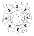
- the device 10 shown in FIGS. 1 and 2 for wide-angle projection simulates the environment of an airport tower and serves to train air traffic controllers.
- the device 10 comprises a tower replica 12, the outer contour of which is in cross section (Fig. 2) has the shape of an even octagon.
- the tower replica 12 has one arranged on a floor 15 Base 14, the surface of which forms a platform, on which control panels 16 are arranged along their circumference. Adjacent to the upper edge of the control panels 16, the Tower replica 12 a conically widening outwards Window area 18 on which a horizontally arranged Ceiling 19 connects.
- the tower replica 12 is one Surrounded canvas 20 coaxially to the tower replica 12, which is spherically concave and extends from the bottom 15 of the Device 10 up to the height of the top surface of the ceiling 19 extends.
- Each mirror 22a to 22e has a spherical on its side facing the canvas 20 convex mirror surface 32 (Fig. 4, Fig. 5). Between each mirror 22a to 22e and the screen 20 is one Projector 24a to 24e in an adjoining the screen 20 Recess 26 arranged in the bottom 15. Each projector 24a to 24e has a lens 28 which is in the direction of the central axis M obliquely on the respective mirror 22a to 22e is directed above.
- a reference viewpoint B BZ which lies on the central axis M of the tower replica at a height between a viewpoint B ST of a person standing at a control panel 16 and a viewpoint B SI of a person sitting at the control panel.
- the height of the screen 20 and its distance from the reference viewpoint B BZ are selected so that the screen extends between two straight lines g 1 and g 2 , the line g 1 extending from the reference viewpoint B BZ at an angle ⁇ 1 to the extends through the reference viewpoint B BZ horizontal H extends upwards.
- the straight line g 2 extends from the reference point of view B BZ at an angle ⁇ 2 to the horizontal H downwards.
- the angles ⁇ 1 and ⁇ 2 are each preferably 20 °.
- the distance of a projector 24 from the associated mirror 22 is chosen so that each mirror 22 has the full cone of light a projector 24 can deflect on the screen 20 so that that of two neighboring mirrors 22 onto the screen 20 deflected light cone only in a small area 30 (Fig. 2) overlap on canvas 20.
- the projectors 24a to 24e are arranged such that they cannot be seen from the viewpoints B ST and B SI , so that a person at the control panel 16 has a clear view of the screen 20.
- the individual projectors 24a to 24e are operated by a computer controlled so that they simulated on the screen 20 Generate all-round image, that of a 360 ° view from an aircraft tower equivalent.
- the center of curvature K L of the screen 20 and the center of curvature K a to K e of the mirrors 22a to 22e match.
- the radius of curvature r s of the mirrors is approximately 3.34 m.
- the radius of curvature K L of the screen is approximately 6.45 m.
- the canvas 20 consists, for example, of fire retardant Glass fiber plastic and is coated in matt white.
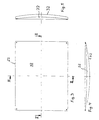
- the design of the mirror 22 is shown in more detail in FIGS. 3 to 5.
- the mirror 22 is made of a spherical segment with a rectangular shape Outer contour (Fig. 3) formed. It preferably exists made of polished aluminum on the mirror surface 32, which with Chrome is coated. However, it is also possible to use mirrors a polished glass surface.
- Another Possibility is a mylar film stretched on a round frame, which is arched outwards by means of air pressure, around which to achieve convex shape.
Landscapes
- Physics & Mathematics (AREA)
- General Physics & Mathematics (AREA)
- Overhead Projectors And Projection Screens (AREA)
- Lenses (AREA)
- Projection Apparatus (AREA)
- Stereoscopic And Panoramic Photography (AREA)
- Fittings On The Vehicle Exterior For Carrying Loads, And Devices For Holding Or Mounting Articles (AREA)
- Load-Engaging Elements For Cranes (AREA)
- Stringed Musical Instruments (AREA)
Claims (5)
- Dispositif pour projection grand angle, muni d'au moins un projecteur (24), devant l'objectif (28) duquel est placé un miroir (22) ayant une surface de miroir (32) formée de manière sphérique convexe, la surface de miroir (32) étant tournée vers un écran de projection (20) essentiellement formé de manière sphérique concave, caractérisé en ce que les centres de courbure (Ka ; Ke ; KL) de la surface de miroir (32) et de l'écran de projection (20) coïncident.
- Dispositif pour projection grand angle selon la revendication 1, caractérisé en ce que le projecteur (24) est placé de telle manière qu'il est invisible à tout observateur de l'écran de projection (20).
- Dispositif pour projection grand angle selon la revendication 1, caractérisé en ce qu'un projecteur à valve optique est utilisé comme projecteur (24).
- Dispositif pour la simulation d'une tour de contrôle, avecune reproduction d'une tour de contrôle (12) placée de manière centraleplusieurs projecteurs (24) avec objectifs (28) installés à écart angulaire régulier autour de la reproduction d'une tour de contrôle (12), les objectifs (28) étant tournés vers la reproduction d'une tour de contrôle (12),plusieurs miroirs (22) placés à écart angulaire régulier autour de la reproduction d'une tour de contrôle (12), installés respectivement devant l'objectif (28) d'un projecteur (24) et présentant une surface de miroir (32) formée de manière sphérique convexe et détournée de la reproduction d'une tour de contrôle (12), etun écran de projection (20) formé de manière sphérique concave et entourant la reproduction d'une tour de contrôle (12), les projecteurs (24) et les miroirs (22).
- Dispositif selon la revendication 4, caractérisé en ce que les centres de courbure (Ka ; Ke ; KL) de la surface de miroir (32) et de l'écran de projection (20) coïncident.
Applications Claiming Priority (3)
| Application Number | Priority Date | Filing Date | Title |
|---|---|---|---|
| DE19805507 | 1998-02-11 | ||
| DE19805507A DE19805507A1 (de) | 1998-02-11 | 1998-02-11 | Vorrichtung für eine Weitwinkelprojektion |
| PCT/EP1999/000897 WO1999041641A1 (fr) | 1998-02-11 | 1999-02-11 | Procede et dispositif pour projection grand angle |
Publications (2)
| Publication Number | Publication Date |
|---|---|
| EP1055152A1 EP1055152A1 (fr) | 2000-11-29 |
| EP1055152B1 true EP1055152B1 (fr) | 2002-07-24 |
Family
ID=7857345
Family Applications (1)
| Application Number | Title | Priority Date | Filing Date |
|---|---|---|---|
| EP99908877A Expired - Lifetime EP1055152B1 (fr) | 1998-02-11 | 1999-02-11 | Dispositif pour projection grand angle |
Country Status (5)
| Country | Link |
|---|---|
| EP (1) | EP1055152B1 (fr) |
| AT (1) | ATE221214T1 (fr) |
| CA (1) | CA2325495A1 (fr) |
| DE (3) | DE19805507A1 (fr) |
| WO (1) | WO1999041641A1 (fr) |
Families Citing this family (2)
| Publication number | Priority date | Publication date | Assignee | Title |
|---|---|---|---|---|
| FR2868552A1 (fr) * | 2004-03-30 | 2005-10-07 | Thomson Licensing Sa | Module de projection, moteur optique et appareil de projection correspondant |
| CH706805A1 (de) * | 2012-08-06 | 2014-02-14 | Haag Ag Streit | Augenuntersuchungsgerät. |
Family Cites Families (11)
| Publication number | Priority date | Publication date | Assignee | Title |
|---|---|---|---|---|
| US3695751A (en) * | 1969-10-30 | 1972-10-03 | Midori Kai Co Ltd | Hemispherical motion picture screen |
| US3807849A (en) * | 1970-05-15 | 1974-04-30 | Redifon Ltd | Visual display arrangements |
| US3880509A (en) * | 1974-03-15 | 1975-04-29 | Us Navy | Wide-angle on-axis projection system |
| US3998532A (en) * | 1974-04-08 | 1976-12-21 | The United States Of America As Represented By The Secretary Of The Navy | Wide angle single channel projection apparatus |
| FR2404243A1 (fr) * | 1977-09-21 | 1979-04-20 | Jaulmes Philippe | Procede de projection et de prise de vue pour simulateur de vol, et salle de projection permettant sa mise en oeuvre |
| DE3529819C2 (de) * | 1985-08-16 | 1994-11-03 | Hertz Inst Heinrich | Projektionseinrichtung zum Erzeugen autostereoskopisch betrachtbarer Bilder |
| DE3618993A1 (de) * | 1986-06-05 | 1987-12-10 | Demolux | Overhead-projektor |
| FR2661766B1 (fr) * | 1990-05-02 | 1992-07-03 | Thomson Csf | Augmentation du champ vertical d'un systeme de projection collimatee a grand champ horizontal pour simulateur de vol. |
| FR2669746B1 (fr) * | 1990-11-23 | 1994-03-04 | Thomson Csf | Dispositif de visualisation collimate a miroir spherique hors d'axe pour simulateur. |
| DE4221375A1 (de) * | 1992-07-01 | 1994-01-05 | Holzer Walter | Spiegel für Auflichtprojektoren |
| GB2298497B (en) * | 1995-03-02 | 1997-05-21 | Robin Christopher Colclough | Image display device |
-
1998
- 1998-02-11 DE DE19805507A patent/DE19805507A1/de not_active Withdrawn
- 1998-03-05 DE DE29803898U patent/DE29803898U1/de not_active Expired - Lifetime
-
1999
- 1999-02-11 WO PCT/EP1999/000897 patent/WO1999041641A1/fr not_active Ceased
- 1999-02-11 EP EP99908877A patent/EP1055152B1/fr not_active Expired - Lifetime
- 1999-02-11 DE DE59902117T patent/DE59902117D1/de not_active Expired - Fee Related
- 1999-02-11 AT AT99908877T patent/ATE221214T1/de not_active IP Right Cessation
- 1999-02-11 CA CA002325495A patent/CA2325495A1/fr not_active Abandoned
Also Published As
| Publication number | Publication date |
|---|---|
| EP1055152A1 (fr) | 2000-11-29 |
| DE59902117D1 (de) | 2002-08-29 |
| DE29803898U1 (de) | 1998-05-28 |
| WO1999041641A1 (fr) | 1999-08-19 |
| DE19805507A1 (de) | 1999-08-12 |
| CA2325495A1 (fr) | 1999-08-19 |
| ATE221214T1 (de) | 2002-08-15 |
Similar Documents
| Publication | Publication Date | Title |
|---|---|---|
| DE2223197A1 (de) | Geraet fuer die kollimierte visuelle wiedergabe einer bildlichen szene, insbesondere bei einem fahrzeugsimulator | |
| DE68914755T2 (de) | System zur Wiedergabe der visuellen Umgebung eines Piloten im Simulator. | |
| DE69103734T2 (de) | Kollimierte Anzeigvorrichtung mit einem aussen, axialen, sphärischen Spiegel für einen Simulator. | |
| DE60023295T2 (de) | Schiessübungssimulationsgerät | |
| DE102007014298A1 (de) | Headup-Display-Vorrichtung | |
| DE19651361A1 (de) | Sandkasten-Anordnung | |
| DE3300728A1 (de) | Ein im infraroten spektralbereich arbeitendes optisches beobachtungssystem | |
| DE3641049A1 (de) | Projektor fuer fixsternprojektion | |
| DE2734376A1 (de) | System zur erzeugung eines panoramabildes | |
| DE102004050574B4 (de) | Vorrichtung zur Darstellung von optischen Informationen mittels eines virtuellen Bildes, insbesondere in einem Kraftfahrzeug | |
| EP1055152B1 (fr) | Dispositif pour projection grand angle | |
| DE1623438A1 (de) | Verfahren und Einrichtung zum Stabilisieren eines optischen Strahlenbuendels,insbesondere fuer Geraete zum UEbungsschiessen mit fernlenkbaren Geschossen | |
| DE2009200A1 (de) | Anzeigevorrichtung zur Wiedergabe von relativ zueinander bewegbaren Symbolen | |
| DE69504076T2 (de) | Abbildungsvorrichtung | |
| DE2554972A1 (de) | Schiffssimulator | |
| DE1622978B1 (de) | Optische projektionsvorrichtung | |
| DE470028C (de) | Rundblickgeraet | |
| DE102017221981A1 (de) | Mikrospiegelbasierte Vorrichtung zum Aussenden von Lichtstrahlen | |
| DE3524262A1 (de) | Einrichtung zur darstellung von rotationssymmetrischen koerpern | |
| DE10123864A1 (de) | Verfahren zum Aufbringen von Mustern auf großflächigen Kunststoffteilen | |
| DE10135450A1 (de) | Projektionssystem | |
| DE2945552A1 (de) | Verfahren und vorrichtung zur ueberpruefung opto-elektronischer geraete | |
| DE102005053361B4 (de) | Sendevorrichtung mit optischem Emitter und Strahlformungseinheit und Kraftfahrzeug mit einer solchen Sendevorrichtung | |
| EP0402479A1 (fr) | Planetarium | |
| DE504615C (de) | Einrichtung zur Aufnahme von in verschiedenen Abstaenden befindlichen Objekten auf denselben Film |
Legal Events
| Date | Code | Title | Description |
|---|---|---|---|
| PUAI | Public reference made under article 153(3) epc to a published international application that has entered the european phase |
Free format text: ORIGINAL CODE: 0009012 |
|
| 17P | Request for examination filed |
Effective date: 20000824 |
|
| AK | Designated contracting states |
Kind code of ref document: A1 Designated state(s): AT CH DE ES FR GB GR IT LI NL SE |
|
| RTI1 | Title (correction) |
Free format text: DEVICE FOR WIDE-ANGLE PROJECTION |
|
| GRAG | Despatch of communication of intention to grant |
Free format text: ORIGINAL CODE: EPIDOS AGRA |
|
| RTI1 | Title (correction) |
Free format text: DEVICE FOR WIDE-ANGLE PROJECTION |
|
| 17Q | First examination report despatched |
Effective date: 20010926 |
|
| GRAG | Despatch of communication of intention to grant |
Free format text: ORIGINAL CODE: EPIDOS AGRA |
|
| GRAH | Despatch of communication of intention to grant a patent |
Free format text: ORIGINAL CODE: EPIDOS IGRA |
|
| GRAH | Despatch of communication of intention to grant a patent |
Free format text: ORIGINAL CODE: EPIDOS IGRA |
|
| GRAA | (expected) grant |
Free format text: ORIGINAL CODE: 0009210 |
|
| AK | Designated contracting states |
Kind code of ref document: B1 Designated state(s): AT CH DE ES FR GB GR IT LI NL SE |
|
| PG25 | Lapsed in a contracting state [announced via postgrant information from national office to epo] |
Ref country code: NL Free format text: LAPSE BECAUSE OF FAILURE TO SUBMIT A TRANSLATION OF THE DESCRIPTION OR TO PAY THE FEE WITHIN THE PRESCRIBED TIME-LIMIT Effective date: 20020724 Ref country code: IT Free format text: LAPSE BECAUSE OF FAILURE TO SUBMIT A TRANSLATION OF THE DESCRIPTION OR TO PAY THE FEE WITHIN THE PRESCRIBED TIME-LIMIT;WARNING: LAPSES OF ITALIAN PATENTS WITH EFFECTIVE DATE BEFORE 2007 MAY HAVE OCCURRED AT ANY TIME BEFORE 2007. THE CORRECT EFFECTIVE DATE MAY BE DIFFERENT FROM THE ONE RECORDED. Effective date: 20020724 Ref country code: GR Free format text: LAPSE BECAUSE OF FAILURE TO SUBMIT A TRANSLATION OF THE DESCRIPTION OR TO PAY THE FEE WITHIN THE PRESCRIBED TIME-LIMIT Effective date: 20020724 Ref country code: GB Free format text: LAPSE BECAUSE OF FAILURE TO SUBMIT A TRANSLATION OF THE DESCRIPTION OR TO PAY THE FEE WITHIN THE PRESCRIBED TIME-LIMIT Effective date: 20020724 Ref country code: FR Free format text: LAPSE BECAUSE OF NON-PAYMENT OF DUE FEES Effective date: 20020724 |
|
| REF | Corresponds to: |
Ref document number: 221214 Country of ref document: AT Date of ref document: 20020815 Kind code of ref document: T |
|
| REG | Reference to a national code |
Ref country code: GB Ref legal event code: FG4D Free format text: NOT ENGLISH |
|
| REG | Reference to a national code |
Ref country code: CH Ref legal event code: EP |
|
| REF | Corresponds to: |
Ref document number: 59902117 Country of ref document: DE Date of ref document: 20020829 |
|
| PG25 | Lapsed in a contracting state [announced via postgrant information from national office to epo] |
Ref country code: SE Free format text: LAPSE BECAUSE OF FAILURE TO SUBMIT A TRANSLATION OF THE DESCRIPTION OR TO PAY THE FEE WITHIN THE PRESCRIBED TIME-LIMIT Effective date: 20021024 |
|
| NLV1 | Nl: lapsed or annulled due to failure to fulfill the requirements of art. 29p and 29m of the patents act | ||
| GBV | Gb: ep patent (uk) treated as always having been void in accordance with gb section 77(7)/1977 [no translation filed] |
Effective date: 20020724 |
|
| PG25 | Lapsed in a contracting state [announced via postgrant information from national office to epo] |
Ref country code: ES Free format text: LAPSE BECAUSE OF FAILURE TO SUBMIT A TRANSLATION OF THE DESCRIPTION OR TO PAY THE FEE WITHIN THE PRESCRIBED TIME-LIMIT Effective date: 20030130 |
|
| PG25 | Lapsed in a contracting state [announced via postgrant information from national office to epo] |
Ref country code: AT Free format text: LAPSE BECAUSE OF NON-PAYMENT OF DUE FEES Effective date: 20030211 |
|
| EN | Fr: translation not filed | ||
| PG25 | Lapsed in a contracting state [announced via postgrant information from national office to epo] |
Ref country code: LI Free format text: LAPSE BECAUSE OF NON-PAYMENT OF DUE FEES Effective date: 20030228 Ref country code: CH Free format text: LAPSE BECAUSE OF NON-PAYMENT OF DUE FEES Effective date: 20030228 |
|
| PLBE | No opposition filed within time limit |
Free format text: ORIGINAL CODE: 0009261 |
|
| STAA | Information on the status of an ep patent application or granted ep patent |
Free format text: STATUS: NO OPPOSITION FILED WITHIN TIME LIMIT |
|
| 26N | No opposition filed |
Effective date: 20030425 |
|
| PG25 | Lapsed in a contracting state [announced via postgrant information from national office to epo] |
Ref country code: DE Free format text: LAPSE BECAUSE OF NON-PAYMENT OF DUE FEES Effective date: 20030902 |
|
| REG | Reference to a national code |
Ref country code: CH Ref legal event code: PL |