EP1055152B1 - Device for wide-angle projection - Google Patents
Device for wide-angle projection Download PDFInfo
- Publication number
- EP1055152B1 EP1055152B1 EP99908877A EP99908877A EP1055152B1 EP 1055152 B1 EP1055152 B1 EP 1055152B1 EP 99908877 A EP99908877 A EP 99908877A EP 99908877 A EP99908877 A EP 99908877A EP 1055152 B1 EP1055152 B1 EP 1055152B1
- Authority
- EP
- European Patent Office
- Prior art keywords
- tower
- projector
- screen
- wide
- angle projection
- Prior art date
- Legal status (The legal status is an assumption and is not a legal conclusion. Google has not performed a legal analysis and makes no representation as to the accuracy of the status listed.)
- Expired - Lifetime
Links
- 238000004088 simulation Methods 0.000 claims description 3
- 238000000034 method Methods 0.000 abstract description 4
- 229920002799 BoPET Polymers 0.000 description 1
- VYZAMTAEIAYCRO-UHFFFAOYSA-N Chromium Chemical compound [Cr] VYZAMTAEIAYCRO-UHFFFAOYSA-N 0.000 description 1
- 239000005041 Mylar™ Substances 0.000 description 1
- XAGFODPZIPBFFR-UHFFFAOYSA-N aluminium Chemical compound [Al] XAGFODPZIPBFFR-UHFFFAOYSA-N 0.000 description 1
- 229910052782 aluminium Inorganic materials 0.000 description 1
- 239000003063 flame retardant Substances 0.000 description 1
- 239000011521 glass Substances 0.000 description 1
- 239000003365 glass fiber Substances 0.000 description 1
- 238000003384 imaging method Methods 0.000 description 1
- 238000004519 manufacturing process Methods 0.000 description 1
- 239000004033 plastic Substances 0.000 description 1
Images

Classifications
-
- G—PHYSICS
- G03—PHOTOGRAPHY; CINEMATOGRAPHY; ANALOGOUS TECHNIQUES USING WAVES OTHER THAN OPTICAL WAVES; ELECTROGRAPHY; HOLOGRAPHY
- G03B—APPARATUS OR ARRANGEMENTS FOR TAKING PHOTOGRAPHS OR FOR PROJECTING OR VIEWING THEM; APPARATUS OR ARRANGEMENTS EMPLOYING ANALOGOUS TECHNIQUES USING WAVES OTHER THAN OPTICAL WAVES; ACCESSORIES THEREFOR
- G03B21/00—Projectors or projection-type viewers; Accessories therefor
- G03B21/54—Accessories
- G03B21/56—Projection screens
-
- G—PHYSICS
- G03—PHOTOGRAPHY; CINEMATOGRAPHY; ANALOGOUS TECHNIQUES USING WAVES OTHER THAN OPTICAL WAVES; ELECTROGRAPHY; HOLOGRAPHY
- G03B—APPARATUS OR ARRANGEMENTS FOR TAKING PHOTOGRAPHS OR FOR PROJECTING OR VIEWING THEM; APPARATUS OR ARRANGEMENTS EMPLOYING ANALOGOUS TECHNIQUES USING WAVES OTHER THAN OPTICAL WAVES; ACCESSORIES THEREFOR
- G03B21/00—Projectors or projection-type viewers; Accessories therefor
- G03B21/14—Details
- G03B21/28—Reflectors in projection beam
Definitions
- the invention relates to a method and an apparatus for a wide-angle projection, especially for a simulation of a tower at an airport.
- US-A-4 464 029 describes an apparatus for a Wide-angle projection with a projector, one spherical convex mirror and a spherically concave screen.
- a similar device is known from US-A-5 253 116.
- the device for a wide-angle projection according to the Claim 1 differs from that the device known from US 4,464,029 in that the centers of curvature the mirror surface and the screen match. This will achieved a very high image quality on the screen.
- the invention has for its object with constructive simple means to create a method and a device, which is a wide-angle projection with little loss of light intensity enable.
- the spherical convex mirror enables extreme widening of the light cone, resulting in little loss of light intensity an enormous image size with a small distance between the projector is effected.
- the best image quality is achieved when the centers of curvature the mirror surface and the screen match or close to each other.
- Computer-controlled light valve projectors are preferably used as projectors used.
- the device 10 shown in FIGS. 1 and 2 for wide-angle projection simulates the environment of an airport tower and serves to train air traffic controllers.
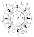
- the device 10 comprises a tower replica 12, the outer contour of which is in cross section (Fig. 2) has the shape of an even octagon.
- the tower replica 12 has one arranged on a floor 15 Base 14, the surface of which forms a platform, on which control panels 16 are arranged along their circumference. Adjacent to the upper edge of the control panels 16, the Tower replica 12 a conically widening outwards Window area 18 on which a horizontally arranged Ceiling 19 connects.
- the tower replica 12 is one Surrounded canvas 20 coaxially to the tower replica 12, which is spherically concave and extends from the bottom 15 of the Device 10 up to the height of the top surface of the ceiling 19 extends.
- Each mirror 22a to 22e has a spherical on its side facing the canvas 20 convex mirror surface 32 (Fig. 4, Fig. 5). Between each mirror 22a to 22e and the screen 20 is one Projector 24a to 24e in an adjoining the screen 20 Recess 26 arranged in the bottom 15. Each projector 24a to 24e has a lens 28 which is in the direction of the central axis M obliquely on the respective mirror 22a to 22e is directed above.
- a reference viewpoint B BZ which lies on the central axis M of the tower replica at a height between a viewpoint B ST of a person standing at a control panel 16 and a viewpoint B SI of a person sitting at the control panel.
- the height of the screen 20 and its distance from the reference viewpoint B BZ are selected so that the screen extends between two straight lines g 1 and g 2 , the line g 1 extending from the reference viewpoint B BZ at an angle ⁇ 1 to the extends through the reference viewpoint B BZ horizontal H extends upwards.
- the straight line g 2 extends from the reference point of view B BZ at an angle ⁇ 2 to the horizontal H downwards.
- the angles ⁇ 1 and ⁇ 2 are each preferably 20 °.
- the distance of a projector 24 from the associated mirror 22 is chosen so that each mirror 22 has the full cone of light a projector 24 can deflect on the screen 20 so that that of two neighboring mirrors 22 onto the screen 20 deflected light cone only in a small area 30 (Fig. 2) overlap on canvas 20.
- the projectors 24a to 24e are arranged such that they cannot be seen from the viewpoints B ST and B SI , so that a person at the control panel 16 has a clear view of the screen 20.
- the individual projectors 24a to 24e are operated by a computer controlled so that they simulated on the screen 20 Generate all-round image, that of a 360 ° view from an aircraft tower equivalent.
- the center of curvature K L of the screen 20 and the center of curvature K a to K e of the mirrors 22a to 22e match.
- the radius of curvature r s of the mirrors is approximately 3.34 m.
- the radius of curvature K L of the screen is approximately 6.45 m.
- the canvas 20 consists, for example, of fire retardant Glass fiber plastic and is coated in matt white.
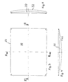
- the design of the mirror 22 is shown in more detail in FIGS. 3 to 5.
- the mirror 22 is made of a spherical segment with a rectangular shape Outer contour (Fig. 3) formed. It preferably exists made of polished aluminum on the mirror surface 32, which with Chrome is coated. However, it is also possible to use mirrors a polished glass surface.
- Another Possibility is a mylar film stretched on a round frame, which is arched outwards by means of air pressure, around which to achieve convex shape.
Landscapes
- Physics & Mathematics (AREA)
- General Physics & Mathematics (AREA)
- Overhead Projectors And Projection Screens (AREA)
- Lenses (AREA)
- Projection Apparatus (AREA)
- Stereoscopic And Panoramic Photography (AREA)
- Fittings On The Vehicle Exterior For Carrying Loads, And Devices For Holding Or Mounting Articles (AREA)
- Load-Engaging Elements For Cranes (AREA)
- Stringed Musical Instruments (AREA)
Abstract
Description
Die Erfindung betrifft ein Verfahren und eine Vorrichtung für eine Weitwinkelprojektion, die insbesondere für eine Simulation eines Towers auf einem Flughafen verwendet werden können.The invention relates to a method and an apparatus for a wide-angle projection, especially for a simulation of a tower at an airport.
Es ist aus dem Stand der Technik bekannt, für eine Weitwinkelprojektion Projektoren mit einer Fischaugenoptik zu verwenden, durch die das den Projektor verlassende Licht aufgeweitet wird. Die Herstellung dieser Fischaugenoptiken ist jedoch sehr aufwendig und erfordert höchste Präzision. Darüber hinaus entsteht bei der Verwendung einer Fischaugenoptik ein erheblicher Lichtverlust durch das Linsensystem.It is known from the prior art for wide-angle projection To use projectors with fisheye optics widened by the light leaving the projector becomes. However, the manufacture of these fisheye optics is very complex and requires maximum precision. Furthermore a significant one arises when using a fisheye optic Loss of light through the lens system.
US-A-4 464 029 beschreibt eine Vorrichtung für eine Weitwinkelprojektion mit einem Projektor, einem sphärisch konvexen Spiegel und einer sphärisch konkaven Leinwand. Eine ähnliche Vorrichtung ist aus US-A-5 253 116 bekannt.US-A-4 464 029 describes an apparatus for a Wide-angle projection with a projector, one spherical convex mirror and a spherically concave screen. A similar device is known from US-A-5 253 116.
Die Vorrichtung für eine Weitwinkelprojektion gemäß dem
Patentanspruch 1 unterscheidet sich von der aus
der US 4,464,029 bekannten Vorrichtung dadurch, daß die Krümmungsmittelpunkte
der Spiegelfläche und der Leinwand übereinstimmen.
Hierdurch wird
eine sehr hohe Bildqualität auf der Leinwand erreicht.The device for a wide-angle projection according to the
Bei der aus der US 4,464,029 bekannten Vorrichtung befindet sich der Spiegel auf dem Krümmungsmittelpunkt der Leinwand. Der Krümmungsmittelpunkt des Spiegels ist sehr weit von dem Krümmungsmittelpunkt der Leinwand entfernt.In the device known from US 4,464,029 the mirror on the center of curvature of the canvas. The center of curvature of the mirror is very far from that Removed the center of curvature of the canvas.
Bei dem aus der US 5,253,116 bekannten Stand der Technik ist die sphärische Leinwand konvex und die sphärische Spiegelfläche konkav ausgebildet. Die Lage der Krümmungsmittelpunkte der Leinwand und des Spiegels ist in dieser Druckschrift nicht angegeben. Den Zeichnungen läßt sich jedoch entnehmen, daß die Krümmungsmittelpunkte weit von einander entfernt sind.In the prior art known from US 5,253,116 the spherical canvas is convex and the spherical mirror surface concave. The location of the centers of curvature the canvas and the mirror is in this publication not specified. However, the drawings show that the centers of curvature are far apart are.
Der Erfindung liegt die Aufgabe zugrunde, mit konstruktiv einfachen Mitteln ein Verfahren und eine Vorrichtung zu schaffen, die eine Weitwinkelprojektion mit wenig Lichtstärkenverlust ermöglichen.The invention has for its object with constructive simple means to create a method and a device, which is a wide-angle projection with little loss of light intensity enable.
Die Aufgabe wird auch durch eine Vorrichtung gelöst wie sie in den Ansprüchen dargestellt ist. The task is also accomplished by a device solved as shown in the claims.
Der sphärisch konvexe Spiegel ermöglicht eine extreme Aufweitung des Lichtkegels, wodurch mit wenig Lichtstärkenverlust eine enorme Bildgröße bei geringem Abstand des Projektors bewirkt wird.The spherical convex mirror enables extreme widening of the light cone, resulting in little loss of light intensity an enormous image size with a small distance between the projector is effected.
Die beste Bildqualität wird erreicht, wenn die Krümmungsmittelpunkte der Spiegelfläche und der Leinwand übereinstimmen oder nahe zueinander liegen.The best image quality is achieved when the centers of curvature the mirror surface and the screen match or close to each other.
Eventuell entstehende Bildverzerrungen auf der Leinwand können durch entsprechende Leinwandform oder Bildvorverzerrung ausgeglichen werden.Possible image distortions on the canvas can compensated by appropriate canvas shape or pre-distortion become.
Als Projektoren werden vorzugsweise rechnergesteuerte Lichtventilprojektoren verwendet.Computer-controlled light valve projectors are preferably used as projectors used.
Ein Ausführungsbeispiel der Erfindung wird nachstehend anhand der Zeichnungen näher erläutert. Es zeigen
- Fig. 1
- eine im Querschnitt eine Vorrichtung für eine Weitwinkelprojektion, die zur Simulation eines Flughafentowers dient;
- Fig. 2
- eine Draufsicht auf die Vorrichtung von Fig. 1;
- Fig. 3
- eine Vorderansicht eines in der Vorrichtung von Fig. 1 verwendeten Spiegels;
- Fig. 4
- den Schnitt II-II von Fig. 3;
- Fig. 5
- den Schnitt III-III von Fig. 3.
- Fig. 1
- a cross-section of a device for a wide-angle projection, which is used to simulate an airport tower;
- Fig. 2
- a plan view of the device of Fig. 1;
- Fig. 3
- a front view of a mirror used in the device of Fig. 1;
- Fig. 4
- the section II-II of Fig. 3;
- Fig. 5
- the section III-III of Fig. 3rd
Die in den Fig. 1 und 2 gezeigte Vorrichtung 10 zur Weitwinkelprojektion
simuliert die Umgebung eines Flughafen-Towers
und dient zur Ausbildung von Fluglotsen. Die Vorrichtung 10
umfaßt einen Towernachbau 12, dessen Außenkontur im Querschnitt
(Fig. 2) die Form eines gleichmäßigen Achtecks hat. The
Der Towernachbau 12 weist einen auf einem Boden 15 angeordneten
Sockel 14 auf, dessen Oberfläche eine Plattform bildet,
auf der längs ihres Umfangs Bedienpulte 16 angeordnet sind.
Angrenzend an die Oberkante der Bedienpulte 16 weist der
Towernachbau 12 einen sich konisch nach außen erweiternden
Fensterbereich 18 auf, an den eine waagerecht angeordnete
Decke 19 anschließt. Der Towernachbau 12 wird von einer
koaxial zum Towernachbau 12 angeordneten Leinwand 20 umgeben,
die sphärisch konkav ausgebildet ist und sich vom Boden 15 der
Vorrichtung 10 bis zur Höhe der oberen Oberfläche der Decke 19
erstreckt.The
Auf jedem Flächenabschnitt der Außenkontur des Towernachbaus
12 ist nach unten an den Fensterbereich 18 angrenzend zentral
ein Spiegel 22a bis 22e befestigt. Jeder Spiegel 22a bis 22e
weist auf seiner der Leinwand 20 zugewandten Seite eine sphärisch
konvexe Spiegelfläche 32 (Fig. 4, Fig. 5) auf. Zwischen
jedem Spiegel 22a bis 22e und der Leinwand 20 ist jeweils ein
Projektor 24a bis 24e in einer an die Leinwand 20 angrenzenden
Vertiefung 26 in dem Boden 15 angeordnet. Jeder Projektor 24a
bis 24e weist ein Objektiv 28 auf, das in Richtung der Mittelachse
M auf den jeweiligen Spiegel 22a bis 22e schräg nach
oben gerichtet ist.On every surface section of the outer contour of the
Zur Auslegung der Vorrichtung 10 wurde ein Bezugsblickpunkt BBZ
herangezogen, der auf der Mittelachse M des Towernachbaus auf
einer Höhe zwischen einem Blickpunkt BST einer an einem Bedienpult
16 stehenden Person und einem Blickpunkt BSI einer an
dem Bedienpult sitzenden Person liegt. Die Höhe der Leinwand
20 und ihr Abstand von dem Bezugsblickpunkt BBZ sind so gewählt,
daß sich die Leinwand zwischen zwei Geraden g1 und g2
erstreckt, wobei die Gerade g1 sich von dem Bezugsblickpunkt
BBZ aus in einem Winkel α1 zu der sich durch den Bezugsblickpunkt
BBZ erstreckenden Horizontalen H nach oben erstreckt. Die
Gerade g2 erstreckt sich von dem Bezugsblickpunkt BBZ aus in
einem Winkel α2 zur Horizontalen H nach unten. Vorzugsweise
betragen die Winkel α1 und α2 jeweils 20°.To design the
Der Abstand eines Projektors 24 von dem zugehörigen Spiegel 22
ist so gewählt, daß jeder Spiegel 22 den vollen Lichtkegel
eines Projektors 24 auf die Leinwand 20 so umlenken kann, daß
sich die von zwei benachbarten Spiegeln 22 auf die Leinwand 20
umgelenkten Lichtkegel nur in einem kleinen Bereich 30 (Fig.
2) auf der Leinwand 20 überschneiden.The distance of a projector 24 from the
Die besten Abbildungsergebnisse werden erreicht, wenn die
Krümmungsmittelpunkte Ka bis Ke der Spiegel 22a bis 22e sehr
nahe an dem Krümmungsmittelpunkt KL der Leinwand 20 befinden,
der auf der Mittelachse M liegt, wie es in Fig. 1 gezeigt ist.
Im Idealfall stimmen die Krümmungsmittelpunkte Ka bis Ke mit
dem Krümmungsmittelpunkt KL überein.The best imaging results are achieved if the centers of curvature K a to K e of the
Die Projektoren 24a bis 24e sind so angeordnet, daß sie von
den Blickpunkten BST und BSI aus nicht zu erkennen sind, so daß
eine Person an dem Bedienpult 16 einen freien Blick auf die
Leinwand 20 hat.The
Die einzelnen Projektoren 24a bis 24e werden von einem Rechner
so gesteuert, daß sie auf der Leinwand 20 ein simuliertes
Rundumbild erzeugen, das einer 360°-Ansicht aus einem Flugzeugtower
entspricht.The
Bei einer bevorzugten Ausführungsform der Vorrichtung zur
Weitwinkelprojektion stimmen der Krümmungsmittelpunkt KL der
Leinwand 20 und die Krümmungsmittelpunkte Ka bis Ke der Spiegel
22a bis 22e überein. Der Krümmungsradius rs der Spiegel beträgt
ungefähr 3,34 m. Der Krümmungsradius KL der Leinwand
beträgt ca. 6,45 m. In a preferred embodiment of the device for wide-angle projection, the center of curvature K L of the
Die Leinwand 20 besteht beispielsweise aus feuerhemmendem
Glasfaserkunststoff und ist mattweiß beschichtet.The
Die Ausbildung der Spiegel 22 ist in Fig. 3 bis 5 näher gezeigt.
Der Spiegel 22 wird von einem Kugelsegment mit rechteckiger
Außenkontur (Fig. 3) gebildet. Er besteht vorzugsweise
aus auf der Spiegelfläche 32 polierten Aluminium, das mit
Chrom beschichtet ist. Es ist jedoch auch möglich, Spiegel mit
einer geschliffenen Glasoberfläche zu verwenden. Eine weitere
Möglichkeit ist eine auf einem runden Rahmen gespannten Mylarfolie,
die mittels Luftdruck nach außen gewölbt wird, um die
konvexe Form zu erreichen.The design of the
Mit der beschriebenen Vorrichtung zur Weitwinkelprojektion ist
es möglich, eine Geometrie auf 10 Bogenminuten genau auf der
Leinwand abzubilden. Durch die Spiegel 22a bis 22e findet eine
extreme Strahlaufweitung statt. Der Lichtverlust durch die
Spiegel 22a bis 22e beträgt lediglich ca. 10%.With the described device for wide-angle projection
it is possible to exactly define a geometry on 10 arc minutes
Map canvas. One finds through the
Claims (5)
- Device for wide-angle projection comprising at least one projector (24), in front of the lens (28) thereof a mirror (22) having a spherically convex mirror surface (32) is arranged, the mirror surface (32) facing a substantially spherically concave screen (20), characterized in that the centers of curvature (Ka; Ke; KL) of the mirror surface (32) and the screen (20) correspond to each other.
- Device for wide-angle projection in accordance with claim 1, characterized in that the projector (24) is arranged such that it is invisible for someone observing the screen (20).
- Device for wide-angle projection in accordance with claim 1, characterized in that a light valve projector is used as the projector (24).
- Device for tower simulation purposes, comprisinga centrally arranged tower imitation (12),several projectors (24) comprising lenses (28), which are arranged around the tower imitation (12) at an even angular distance, the lenses (28) facing the tower imitation (12),several mirrors (22) arranged around the tower imitation (12) at an even angular distance, the mirrors (22) being arranged, respectively, in front of the lens (28) of a projector (24) and having a spherically convex mirror surface (32) that faces away from the tower imitation (12), anda spherically concave screen (20) that surrounds the tower imitation (12), the projectors (24) and the mirrors (22).
- Device according to claim 4, characterized in that the centers of curvature (Ka; Ke; KL) of the mirror surface (32) and of the screen (20) correspond to each other.
Applications Claiming Priority (3)
| Application Number | Priority Date | Filing Date | Title |
|---|---|---|---|
| DE19805507 | 1998-02-11 | ||
| DE19805507A DE19805507A1 (en) | 1998-02-11 | 1998-02-11 | Wide angle projection device |
| PCT/EP1999/000897 WO1999041641A1 (en) | 1998-02-11 | 1999-02-11 | Method and device for wide-angle projection |
Publications (2)
| Publication Number | Publication Date |
|---|---|
| EP1055152A1 EP1055152A1 (en) | 2000-11-29 |
| EP1055152B1 true EP1055152B1 (en) | 2002-07-24 |
Family
ID=7857345
Family Applications (1)
| Application Number | Title | Priority Date | Filing Date |
|---|---|---|---|
| EP99908877A Expired - Lifetime EP1055152B1 (en) | 1998-02-11 | 1999-02-11 | Device for wide-angle projection |
Country Status (5)
| Country | Link |
|---|---|
| EP (1) | EP1055152B1 (en) |
| AT (1) | ATE221214T1 (en) |
| CA (1) | CA2325495A1 (en) |
| DE (3) | DE19805507A1 (en) |
| WO (1) | WO1999041641A1 (en) |
Families Citing this family (2)
| Publication number | Priority date | Publication date | Assignee | Title |
|---|---|---|---|---|
| FR2868552A1 (en) * | 2004-03-30 | 2005-10-07 | Thomson Licensing Sa | Projection module for e.g. overhead projector, has lens with optical axis parallel to screen, two reference mirrors for transmitting image beam from lens towards hyperbolic convex mirror which enlarges and transmits image beam |
| CH706805A1 (en) * | 2012-08-06 | 2014-02-14 | Haag Ag Streit | Eye examination device. |
Family Cites Families (11)
| Publication number | Priority date | Publication date | Assignee | Title |
|---|---|---|---|---|
| US3695751A (en) * | 1969-10-30 | 1972-10-03 | Midori Kai Co Ltd | Hemispherical motion picture screen |
| US3807849A (en) * | 1970-05-15 | 1974-04-30 | Redifon Ltd | Visual display arrangements |
| US3880509A (en) * | 1974-03-15 | 1975-04-29 | Us Navy | Wide-angle on-axis projection system |
| US3998532A (en) * | 1974-04-08 | 1976-12-21 | The United States Of America As Represented By The Secretary Of The Navy | Wide angle single channel projection apparatus |
| FR2404243A1 (en) * | 1977-09-21 | 1979-04-20 | Jaulmes Philippe | PROJECTION AND SHOOTING PROCESS FOR FLIGHT SIMULATOR, AND PROJECTION ROOM ALLOWING ITS IMPLEMENTATION |
| DE3529819C2 (en) * | 1985-08-16 | 1994-11-03 | Hertz Inst Heinrich | Projection device for generating autostereoscopically viewable images |
| DE3618993A1 (en) * | 1986-06-05 | 1987-12-10 | Demolux | Overhead projector |
| FR2661766B1 (en) * | 1990-05-02 | 1992-07-03 | Thomson Csf | INCREASE OF THE VERTICAL FIELD OF A COLLIMATE PROJECTION SYSTEM WITH LARGE HORIZONTAL FIELD FOR FLIGHT SIMULATOR. |
| FR2669746B1 (en) * | 1990-11-23 | 1994-03-04 | Thomson Csf | COLLIMATE VIEWING DEVICE WITH SPHERICAL MIRROR OFF-AXIS FOR A SIMULATOR. |
| DE4221375A1 (en) * | 1992-07-01 | 1994-01-05 | Holzer Walter | Mirror for top-illumination projector - rectifies troublesome distortions which normally occur with projection angle inclined to horizontal |
| GB2298497B (en) * | 1995-03-02 | 1997-05-21 | Robin Christopher Colclough | Image display device |
-
1998
- 1998-02-11 DE DE19805507A patent/DE19805507A1/en not_active Withdrawn
- 1998-03-05 DE DE29803898U patent/DE29803898U1/en not_active Expired - Lifetime
-
1999
- 1999-02-11 WO PCT/EP1999/000897 patent/WO1999041641A1/en not_active Ceased
- 1999-02-11 EP EP99908877A patent/EP1055152B1/en not_active Expired - Lifetime
- 1999-02-11 DE DE59902117T patent/DE59902117D1/en not_active Expired - Fee Related
- 1999-02-11 AT AT99908877T patent/ATE221214T1/en not_active IP Right Cessation
- 1999-02-11 CA CA002325495A patent/CA2325495A1/en not_active Abandoned
Also Published As
| Publication number | Publication date |
|---|---|
| EP1055152A1 (en) | 2000-11-29 |
| DE59902117D1 (en) | 2002-08-29 |
| DE29803898U1 (en) | 1998-05-28 |
| WO1999041641A1 (en) | 1999-08-19 |
| DE19805507A1 (en) | 1999-08-12 |
| CA2325495A1 (en) | 1999-08-19 |
| ATE221214T1 (en) | 2002-08-15 |
Similar Documents
| Publication | Publication Date | Title |
|---|---|---|
| DE2223197A1 (en) | DEVICE FOR THE COLLIMATED VISUAL REPLAY OF A PICTURAL SCENE, IN PARTICULAR WITH A VEHICLE SIMULATOR | |
| DE68914755T2 (en) | System for displaying the visual environment of a pilot in the simulator. | |
| DE69103734T2 (en) | Collimated display device with an external, axial, spherical mirror for a simulator. | |
| DE60023295T2 (en) | SHOOTING EXERCISE DEVICE SIMULATION | |
| DE102007014298A1 (en) | Head-up display device | |
| DE19651361A1 (en) | Sandpit arrangement | |
| DE3300728A1 (en) | AN OPTICAL OBSERVATION SYSTEM WORKING IN THE INFRARED SPECTRAL AREA | |
| DE3641049A1 (en) | PROJECTOR FOR FIXED STAR PROJECTION | |
| DE2734376A1 (en) | SYSTEM FOR GENERATING A PANORAMIC IMAGE | |
| DE102004050574B4 (en) | Device for displaying optical information by means of a virtual image, in particular in a motor vehicle | |
| EP1055152B1 (en) | Device for wide-angle projection | |
| DE1623438A1 (en) | Method and device for stabilizing an optical bundle of rays, in particular for devices for practice shooting with remotely steerable projectiles | |
| DE2009200A1 (en) | Display device for displaying symbols which can be moved relative to one another | |
| DE69504076T2 (en) | IMAGE DEVICE | |
| DE2554972A1 (en) | SHIP SIMULATOR | |
| DE1622978B1 (en) | OPTICAL PROJECTION DEVICE | |
| DE470028C (en) | Panoramic device | |
| DE102017221981A1 (en) | Micromirror-based device for emitting light rays | |
| DE3524262A1 (en) | DEVICE FOR DISPLAYING ROTATIONALLY SYMMETRIC BODIES | |
| DE10123864A1 (en) | Process for applying patterns to large plastic parts | |
| DE10135450A1 (en) | projection system | |
| DE2945552A1 (en) | METHOD AND DEVICE FOR CHECKING OPTO-ELECTRONIC DEVICES | |
| DE102005053361B4 (en) | Transmitting device with optical emitter and beam shaping unit and motor vehicle with such a transmitting device | |
| EP0402479A1 (en) | Planetarium | |
| DE504615C (en) | Device for recording objects at different distances on the same film |
Legal Events
| Date | Code | Title | Description |
|---|---|---|---|
| PUAI | Public reference made under article 153(3) epc to a published international application that has entered the european phase |
Free format text: ORIGINAL CODE: 0009012 |
|
| 17P | Request for examination filed |
Effective date: 20000824 |
|
| AK | Designated contracting states |
Kind code of ref document: A1 Designated state(s): AT CH DE ES FR GB GR IT LI NL SE |
|
| RTI1 | Title (correction) |
Free format text: DEVICE FOR WIDE-ANGLE PROJECTION |
|
| GRAG | Despatch of communication of intention to grant |
Free format text: ORIGINAL CODE: EPIDOS AGRA |
|
| RTI1 | Title (correction) |
Free format text: DEVICE FOR WIDE-ANGLE PROJECTION |
|
| 17Q | First examination report despatched |
Effective date: 20010926 |
|
| GRAG | Despatch of communication of intention to grant |
Free format text: ORIGINAL CODE: EPIDOS AGRA |
|
| GRAH | Despatch of communication of intention to grant a patent |
Free format text: ORIGINAL CODE: EPIDOS IGRA |
|
| GRAH | Despatch of communication of intention to grant a patent |
Free format text: ORIGINAL CODE: EPIDOS IGRA |
|
| GRAA | (expected) grant |
Free format text: ORIGINAL CODE: 0009210 |
|
| AK | Designated contracting states |
Kind code of ref document: B1 Designated state(s): AT CH DE ES FR GB GR IT LI NL SE |
|
| PG25 | Lapsed in a contracting state [announced via postgrant information from national office to epo] |
Ref country code: NL Free format text: LAPSE BECAUSE OF FAILURE TO SUBMIT A TRANSLATION OF THE DESCRIPTION OR TO PAY THE FEE WITHIN THE PRESCRIBED TIME-LIMIT Effective date: 20020724 Ref country code: IT Free format text: LAPSE BECAUSE OF FAILURE TO SUBMIT A TRANSLATION OF THE DESCRIPTION OR TO PAY THE FEE WITHIN THE PRESCRIBED TIME-LIMIT;WARNING: LAPSES OF ITALIAN PATENTS WITH EFFECTIVE DATE BEFORE 2007 MAY HAVE OCCURRED AT ANY TIME BEFORE 2007. THE CORRECT EFFECTIVE DATE MAY BE DIFFERENT FROM THE ONE RECORDED. Effective date: 20020724 Ref country code: GR Free format text: LAPSE BECAUSE OF FAILURE TO SUBMIT A TRANSLATION OF THE DESCRIPTION OR TO PAY THE FEE WITHIN THE PRESCRIBED TIME-LIMIT Effective date: 20020724 Ref country code: GB Free format text: LAPSE BECAUSE OF FAILURE TO SUBMIT A TRANSLATION OF THE DESCRIPTION OR TO PAY THE FEE WITHIN THE PRESCRIBED TIME-LIMIT Effective date: 20020724 Ref country code: FR Free format text: LAPSE BECAUSE OF NON-PAYMENT OF DUE FEES Effective date: 20020724 |
|
| REF | Corresponds to: |
Ref document number: 221214 Country of ref document: AT Date of ref document: 20020815 Kind code of ref document: T |
|
| REG | Reference to a national code |
Ref country code: GB Ref legal event code: FG4D Free format text: NOT ENGLISH |
|
| REG | Reference to a national code |
Ref country code: CH Ref legal event code: EP |
|
| REF | Corresponds to: |
Ref document number: 59902117 Country of ref document: DE Date of ref document: 20020829 |
|
| PG25 | Lapsed in a contracting state [announced via postgrant information from national office to epo] |
Ref country code: SE Free format text: LAPSE BECAUSE OF FAILURE TO SUBMIT A TRANSLATION OF THE DESCRIPTION OR TO PAY THE FEE WITHIN THE PRESCRIBED TIME-LIMIT Effective date: 20021024 |
|
| NLV1 | Nl: lapsed or annulled due to failure to fulfill the requirements of art. 29p and 29m of the patents act | ||
| GBV | Gb: ep patent (uk) treated as always having been void in accordance with gb section 77(7)/1977 [no translation filed] |
Effective date: 20020724 |
|
| PG25 | Lapsed in a contracting state [announced via postgrant information from national office to epo] |
Ref country code: ES Free format text: LAPSE BECAUSE OF FAILURE TO SUBMIT A TRANSLATION OF THE DESCRIPTION OR TO PAY THE FEE WITHIN THE PRESCRIBED TIME-LIMIT Effective date: 20030130 |
|
| PG25 | Lapsed in a contracting state [announced via postgrant information from national office to epo] |
Ref country code: AT Free format text: LAPSE BECAUSE OF NON-PAYMENT OF DUE FEES Effective date: 20030211 |
|
| EN | Fr: translation not filed | ||
| PG25 | Lapsed in a contracting state [announced via postgrant information from national office to epo] |
Ref country code: LI Free format text: LAPSE BECAUSE OF NON-PAYMENT OF DUE FEES Effective date: 20030228 Ref country code: CH Free format text: LAPSE BECAUSE OF NON-PAYMENT OF DUE FEES Effective date: 20030228 |
|
| PLBE | No opposition filed within time limit |
Free format text: ORIGINAL CODE: 0009261 |
|
| STAA | Information on the status of an ep patent application or granted ep patent |
Free format text: STATUS: NO OPPOSITION FILED WITHIN TIME LIMIT |
|
| 26N | No opposition filed |
Effective date: 20030425 |
|
| PG25 | Lapsed in a contracting state [announced via postgrant information from national office to epo] |
Ref country code: DE Free format text: LAPSE BECAUSE OF NON-PAYMENT OF DUE FEES Effective date: 20030902 |
|
| REG | Reference to a national code |
Ref country code: CH Ref legal event code: PL |