EP1054572A2 - Optisches Querverbindungseinrichtung und optisches Netzwerk - Google Patents
Optisches Querverbindungseinrichtung und optisches Netzwerk Download PDFInfo
- Publication number
- EP1054572A2 EP1054572A2 EP00109034A EP00109034A EP1054572A2 EP 1054572 A2 EP1054572 A2 EP 1054572A2 EP 00109034 A EP00109034 A EP 00109034A EP 00109034 A EP00109034 A EP 00109034A EP 1054572 A2 EP1054572 A2 EP 1054572A2
- Authority
- EP
- European Patent Office
- Prior art keywords
- wavelength
- optical
- wavelengths
- output
- input
- Prior art date
- Legal status (The legal status is an assumption and is not a legal conclusion. Google has not performed a legal analysis and makes no representation as to the accuracy of the status listed.)
- Withdrawn
Links
Images


Classifications
-
- H—ELECTRICITY
- H04—ELECTRIC COMMUNICATION TECHNIQUE
- H04Q—SELECTING
- H04Q11/00—Selecting arrangements for multiplex systems
- H04Q11/0001—Selecting arrangements for multiplex systems using optical switching
- H04Q11/0005—Switch and router aspects
-
- H—ELECTRICITY
- H04—ELECTRIC COMMUNICATION TECHNIQUE
- H04Q—SELECTING
- H04Q11/00—Selecting arrangements for multiplex systems
- H04Q11/0001—Selecting arrangements for multiplex systems using optical switching
- H04Q11/0005—Switch and router aspects
- H04Q2011/0007—Construction
- H04Q2011/0009—Construction using wavelength filters
-
- H—ELECTRICITY
- H04—ELECTRIC COMMUNICATION TECHNIQUE
- H04Q—SELECTING
- H04Q11/00—Selecting arrangements for multiplex systems
- H04Q11/0001—Selecting arrangements for multiplex systems using optical switching
- H04Q11/0005—Switch and router aspects
- H04Q2011/0007—Construction
- H04Q2011/0011—Construction using wavelength conversion
-
- H—ELECTRICITY
- H04—ELECTRIC COMMUNICATION TECHNIQUE
- H04Q—SELECTING
- H04Q11/00—Selecting arrangements for multiplex systems
- H04Q11/0001—Selecting arrangements for multiplex systems using optical switching
- H04Q11/0005—Switch and router aspects
- H04Q2011/0007—Construction
- H04Q2011/0015—Construction using splitting combining
-
- H—ELECTRICITY
- H04—ELECTRIC COMMUNICATION TECHNIQUE
- H04Q—SELECTING
- H04Q11/00—Selecting arrangements for multiplex systems
- H04Q11/0001—Selecting arrangements for multiplex systems using optical switching
- H04Q11/0005—Switch and router aspects
- H04Q2011/0007—Construction
- H04Q2011/0016—Construction using wavelength multiplexing or demultiplexing
-
- H—ELECTRICITY
- H04—ELECTRIC COMMUNICATION TECHNIQUE
- H04Q—SELECTING
- H04Q11/00—Selecting arrangements for multiplex systems
- H04Q11/0001—Selecting arrangements for multiplex systems using optical switching
- H04Q11/0005—Switch and router aspects
- H04Q2011/0007—Construction
- H04Q2011/0018—Construction using tunable transmitters or receivers
-
- H—ELECTRICITY
- H04—ELECTRIC COMMUNICATION TECHNIQUE
- H04Q—SELECTING
- H04Q11/00—Selecting arrangements for multiplex systems
- H04Q11/0001—Selecting arrangements for multiplex systems using optical switching
- H04Q11/0005—Switch and router aspects
- H04Q2011/0052—Interconnection of switches
-
- H—ELECTRICITY
- H04—ELECTRIC COMMUNICATION TECHNIQUE
- H04Q—SELECTING
- H04Q11/00—Selecting arrangements for multiplex systems
- H04Q11/0001—Selecting arrangements for multiplex systems using optical switching
- H04Q11/0062—Network aspects
- H04Q2011/0075—Wavelength grouping or hierarchical aspects
Definitions
- the present invention relates to an optical cross connect apparatus or system and an optical network, to which the WDM (Wavelength Division Multiplex) transmission technique is applicable.
- WDM Widelength Division Multiplex
- the WDM transmission is expected as a technique to increase the communication volume without gaining the signal rate by utilizing the optical broadband characteristics effectively.
- the WDM transmission has been introduced initially for the purpose of increasing the number of wavelengths to be multiplexed in the field of the existing point-to-point transmission.
- the configuration of a high-flexibility high-reliability optical network (such as a ring network) has started through the employment of the optical ADM (Add Drop Multiplexer) capable of dropping/adding optical signals in units of wavelengths.
- optical ADM Additional Drop Multiplexer
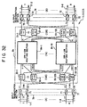
- an optical cross connect system designated generally at reference numeral 100 in FIG. 63, is expected as a next-generation system capable of constructing a higher-flexibility higher-reliability optical network.
- the OCCS 100 in contrast with the existing systems, can accommodate a large number of input/output optical fibers and, additionally, can accept optical signals different in transmission rate from each other, such as an OC (Optical Carrier)-192 (STM (Signal Transfer Module)-64 ⁇ (almost equal) 10 Gb/s) and an OC-48 (STM-16 ⁇ 2.5 Gb/s) and an OC-12 (STM-4 ⁇ 620 Mb/s), through proper optical interfaces 300 to 600 so that the setting [exchange (cross connect)] of optical paths in units of wavelengths is feasible in a manner that an optical routing section (cross connect section) 200 conducts switching (routing) among output paths or performs wavelength conversion for or on these optical signals in units of wavelengths.
- OC Optical Carrier
- STM Signal Transfer Module
- the OCCS 100 accommodates optical fibers constituting a trunk line system for a ring network or the like to form optical links (Inter-Office Link) 700A and 700B and additionally accommodates optical fibers organizing a different network to establish an optical link (Intra-Office Link) with the different network, it becomes possible to add an optical signal from the different network to the trunk line system in units of wavelengths or to drop a portion of an optical signal running on the aforesaid trunk line system to the different network.
- the OCCS 100 is capable of setting up a connection between the existing ring networks put individually in operation or of making a connection of the existing network other than ring networks to a ring network, thus constructing a new large-capacity optical network. For this reason, as a system which plays most important role in a future optical network, much attention has been focused on this OCCS 100.
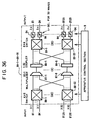
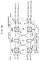
- FIG. 64 is a block diagram showing one example of principle configuration of the optical routing section 200.
- the optical routing section 200 employs a typical non-blocking type switch circuit (three-stage switch configuration), referred to as a cross (Clos) type.
- the first-stage switch unit 200A comprises k n-input 2n-output (n ⁇ 2n) type switch circuits 201
- the second-stage (intermediate-stage) switch unit 200B comprises 2n k-input k-output (k ⁇ k) type switch circuits 202
- the third-stage switch unit 200C comprises k 2n-input n-output (2n ⁇ n) type switch circuits 203.
- the "M ⁇ M switch circuit” taken here signifies a switch which exhibits an ability to switch (selectively establish an output path) any one of M inputs (M denotes an integer being two or more) to any one of the M outputs. Furthermore, the aforesaid k corresponds to the number of input ports (output ports), for example, one optical fiber is connected (accommodated) to one port.
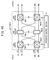
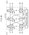
- FIG. 65 shows a detailed configurational example of the optical routing section 200 based upon the foregoing three-stage cross type switch circuit arrangement.
- each of the 16 ⁇ 32 switch circuits 201 of the first-stage switch unit 200A and each of the 32 ⁇ 16 switch circuits 203 of the third-stage switch unit 200C are constructed using two 16 ⁇ 16 switch circuits 211 and 16 1 ⁇ 2 switch circuits 210. That is, in the configuration shown in FIG. 65, the basic size of the switch circuits (basic switch size) becomes 16 ⁇ 16.
- reference numeral 204 depicts each of 8 optical demultiplexer (filters) provided with each of the input ports.
- Each of these optical demultiplexers 204 demultiplexes a wavelength multiplexed optical signal from the corresponding input port according to each of wavelengths ⁇ 1 to ⁇ 32 so that, for example, the optical signals respectively having wavelengths of ⁇ 1 to ⁇ 16 are inputted to the 16 ⁇ 32 switch circuits 201 in odd numbers while the remaining optical signals respectively having wavelengths of ⁇ 17 to ⁇ 32 are inputted to the even-numbered 16 ⁇ 32 switch circuits 201.
- reference numeral 206 designates each of 8 optical multiplexers provided with each of the output ports, and each of the optical multiplexers 206 multiplexes (wavelength-multiplexes) the optical signals, respectively converted in wavelength in the wavelength converters 205, at every output wavelengths ( ⁇ 1 to ⁇ 32) to each of the output ports, and outputs the multiplexed optical signal to the corresponding output port.
- the foregoing optical routing section 200 can output an optical signal with an arbitrary wavelength to an arbitrary input port as an optical signal with a desired wavelength to a desired output port [that is, it is capable of accomplishing the path setting (cross connect) in units of wavelengths].
- the optical signal with an input wavelength of ⁇ 1 to the uppermost output port (1) is outputted as an optical signal with an output wavelength of ⁇ 32 to the lowermost output port (8)
- the optical signal with the input wavelength of ⁇ 1 to the output port (1) is inputted to the lowermost wavelength converter 205.
- the switching setting for the switch units 200A to 200C switch circuits 201 and 202 is made to achieve this input of the optical signal.
- the OCCS 100 provides a large-scale optical switching system different from the existing systems.
- the WDM transmission technique handling a level up to 32-wavelength multiplexing has already been available, and the techniques handling higher levels, such as 64-wavelength multiplexing and 128-wavelength multiplexing are currently at the trial and study stage. For this reason, the aforesaid OCCS 100 needs to accept all of these signals, and reaches a large system scale naturally.
- one point is the size reduction of the system which tends to have a larger scale and the other is to offer an OCCS 100 with a proper system size matching with the needed value of information.
- the latter can namely be handled as an object in the extensibility of the system.
- an increase in the number of wavelengths to be multiplexed is made to cope with an increase in volume of information, which leads naturally to an increase in the system size of the OCCS 100, while it is desirable that this system size is proportional to the increase/decrease in the number of wavelengths.
- the excellent extensibility coping with the increase in the number of wavelengths to be accepted or accommodated constitutes an important point on the development of the OCCS 100 (especially, the optical routing section 200). Additionally, conceivably, for the extension mentioned above, the construction of the OCCS 100 using the existing parts but not using special (new) parts, if possible, also constitutes an important point in view of economy, development procedure, cost reduction and others.
- the increase in the number of wavelengths being accommodated per optical fiber requires a substantial alteration of the configuration of the optical routing section 200, which is remote from excellent extensibility and economy.
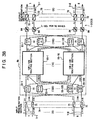
- the number n of wavelengths to be accommodated in each input port is increased from 32 to 128 and the total number N of input/output channels is increased from 256 to 1024.
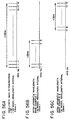
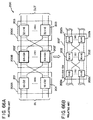
- FIG. 66A shows, for the first-stage (third-stage) switch unit 200A (200C), 64 16 ⁇ 32 switch circuits 201 (32 ⁇ 16 switch circuits 203) each identical to that in the configuration shown in FIG. 65 can be put to use so that the increase in the numbers of the switch circuits 201 and 203 due to the extension is proportional to the increase in the number of wavelengths to be accommodated, whereas, for the second-stage switch unit 200B, there is a need to use 32 64 ⁇ 64 switch circuits 202' different in basic switch size.
- the change of the basic switch size does not constitute the extension of the system. That is, as well known, of optical parts, a switch circuit for use in the optical routing section 200 especially encounters difficulty in large-scale integration and further creates serious problems in technique and cost, and an extremely disadvantageous situation exists in that there is a need to newly develop the 64 ⁇ 64 switch circuit 202'.
- each of the 64x64 switch circuits 202' is reconstructed as a three-stage configuration comprising 8 16 ⁇ 16 switch circuits 202, 16 4 ⁇ 8 switch circuits 202a and 16 8 ⁇ 4 switch circuits 202b, which are implemented in basic switch sizes.
- the optical routing section 200 results in a five-stage configuration as a whole, which causes the alteration of the system itself and is naturally remote from excellent extensibility.
- the number of wavelengths to be multiplexed is increased to deal with the increase in communication capacity, and the increase in the number of optical fibers, by contrast, is seldom taken for coping therewith.
- band characteristics such as an effective wavelength band, a transmission band characteristic, a wavelength splitting characteristic and others, an optical device requires.
- the present invention has been developed in consideration of the above-described objects, and it is therefore an object of the invention to less expensively provide an optical cross connect apparatus having excellent flexibility (extensibility) to cope with a change (particularly, an increase) in the number of wavelengths to be accommodated per input port, and additionally to provide an optical network equipped with the same optical cross connect.
- an optical cross connect apparatus comprises the following components:
- optical cross connect apparatus even if the number of accommodation wavelengths increases or decreases, a change in the number of switch circuits corresponding to this increase/decrease in only the input switch section and the output switch section can cope with the increase/decrease without changing the basic configuration of the optical multiplexing/distributing section, thereby economically realizing an optical cross connect apparatus showing extremely excellent flexibility on the increase/decrease in the number of wavelengths being accommodated.
- a first wavelength converting section for converting an optical signal with an optional input wavelength after the routing operation by the switch circuits of the optical output switch section into an optical signal with a desired output wavelength so that the optical signal with the optional input wavelength coming in the optional input port is outputted as the optical signal with the desired output wavelength through the output port.
- a second wavelength converting section which converts an optical signal with an optical input wavelength before the routing operation by the switch circuits of the optical input switch section into an optical signal with a desired output wavelength can also be provided so that the optical signal with the optional input wavelength coming in the optional input port is outputted as the optical signal with the desired output wavelength through the output port.
- the wavelength converting section which converts an optical signal with an optional input wavelength into an optical signal with a desired output wavelength, is provided in the input switch section or in the output switch section so that the optical signal with the optional input wavelength to an optional input port is outputted as the optical signal with the desired output wavelength through a desired output port; therefore, it becomes possible to avoid the event that optical signals having the same wavelength are outputted simultaneously to the same output port to cause the optical signals with the same wavelength to interfere with each other, which contributes greatly to the improvement of reliability of this system.
- this optical cross connect apparatus accommodates k (k : an integer equal to or more than 2) input ports and k output ports, it is also appropriate that this optical cross connect apparatus is equipped with the following devices.
- the wavelength selectors constitute the optical wavelength selecting section, while the wavelength converters organize the first wavelength converting section.
- this optical cross connect apparatus can also be equipped with the following devices.
- the aforesaid wavelength selectors constitute the optical wavelength selecting section, while the aforesaid wavelength converters organize the first wavelength converting section.
- this optical cross connect apparatus can also include the following devices.
- the aforesaid first coupling/demultiplexing units constitute the optical wavelength selecting section, while the aforesaid wavelength converters organize the second wavelength converting section.
- this optical cross connect apparatus can also be equipped with the following devices.
- the aforesaid second coupling/demultiplexing units constitute the optical wavelength selecting section, while the aforesaid wavelength converters organize the second wavelength converting section.
- this optical cross connect apparatus can also include the following devices.
- the aforesaid wavelength selectors constitute the optical wavelength selecting section, while the aforesaid wavelength converters organize the first wavelength converting section.
- this optical cross connect apparatus can also be equipped with the following devices.
- the wavelength selectors constitute the optical wavelength selecting section
- the wavelength converters constitute the first wavelength converting section
- this optical cross connect apparatus can include the following devices.
- the wavelength selectors constitute the optical wavelength selecting section
- the wavelength converters constitute the second wavelength converting section
- this optical cross connect apparatus can also be equipped with the following devices.
- the wavelength selectors constitute the optical wavelength selecting section, while the wavelength converters organize the second wavelength converting section.
- the input switch section and the output switch section can accept the use of the existing (k ⁇ 2k) switch circuit and the existing (2k ⁇ k) switch circuit
- the optical multiplexing/distributing section can accept the employment of the optical parts, such as a multiplexing/distributing unit, a coupling/demultiplexing unit, which have been used in the existing WDM transmission system; therefore, there is no need to newly design and develop optical parts even if an increase/decrease in the number of wavelengths to be accommodated takes place, thus realizing a system according to this invention within an extremely short period of time and at an extremely low cost.
- each of the above-mentioned input ports each accommodates a wavelength-multiplexed optical signal having a plurality of kinds of input wavelengths while each of the above-mentioned output ports accommodates a wavelength-multiplexed optical signal having a plurality of kinds of output wavelengths.
- a portion of the above-mentioned input ports each accommodates a wavelength-multiplexed optical signal having a plurality of kinds of input wavelengths while the remaining input ports are each used for adding an optical signal having an arbitrary wavelength
- a portion of the above-mentioned output ports each accommodates a wavelength-multiplexed optical signal having a plurality of kinds of output wavelengths while the remaining output ports are each used for dropping an optical signal having an arbitrary wavelength.
- optical cross connect apparatus it is also possible that only the output ports each accommodates a wavelength-multiplexed optical signal having a plurality of kinds of output wavelengths, or that only the input ports each accommodates a wavelength-multiplexed optical signal having a plurality of kinds of wavelengths.
- each of the ports can be allocated properly to dedicated station-to-station transmission, station-to-station/in-station transmission, transmission terminal stations, receive terminal station and others, thereby realizing and providing an optical cross connect apparatus suitable for desired using modes with considerable ease.
- an optical network including at least one optical cross connect apparatus having the above-described configuration.
- optical cross connect apparatus is characterized by comprising the following sections:
- the input wavelength converting section preferably the wavelength multiplexing/distribution routing section and the output wavelength converting section are constructed, for example, as follows.
- each of the n ⁇ n routing sections includes p m:n multiplexing/distributing sections for multiplexing, in terms of wavelengths, optical signals of p sets of different intra-apparatus wavelengths from the k ⁇ 2k switches and further for distributing the resultant intra-apparatus wavelength multiplexed optical signal in the form of n optical signals, n p ⁇ 1 switches each for selecting a desired intra-apparatus wavelength multiplexed optical signal from the p sets of intra-apparatus wavelength multiplexed optical signals from the m:n multiplexing/distributing sections, and n tunable (variable) wavelength filters each for selecting an optical signal of desired intra-apparatus wavelengths from the outputs of the p ⁇ 1 switches, with n tunable wavelength filters constituting the aforesaid optical wavelength selecting section.
- each of the n ⁇ n routing sections includes m p ⁇ 2p switches each for accommodating optical signals of p sets of different intra-apparatus wavelengths from the k ⁇ 2k switches for same intra-apparatus wavelength to route them to arbitrary routes, 2p m:m multiplexing/distributing sections for multiplexing the different intra-apparatus wavelengths of the outputs of the p ⁇ 2p switches to distribute the resultant intra-apparatus wavelength multiplexed optical signal in the form of m optical signals, m 2p ⁇ p switches each for routing the 2p outputs from the m:m multiplexing/distributing sections to any one of p outputs, and n tunable wavelength filters each for selecting an optical signal of desired intra-apparatus wavelength from the outputs of the 2p ⁇ p switches, with the n tunable wavelength filters constituting the aforesaid optical wavelength selecting section.
- the aforesaid optical wavelength selecting section includes n tunable wavelength filters provided outside the n ⁇ n routing section but not provided inside the n ⁇ n routing section, for example, provided at a rear stage of each of the aforesaid 2k ⁇ k switches for selecting an optical signal with a desired intra-apparatus wavelength from the intra-apparatus wavelength multiplexed optical signal from the 2k ⁇ k switches.
- each of the n ⁇ n routing sections includes p m:n multiplexing/distributing sections for multiplexing, in terms of wavelengths, optical signals of p sets of different intra-apparatus wavelengths from the k ⁇ 2k switches to distribute the resultant intra-apparatus wavelength multiplexed optical signal in the form of n optical signals, and n p ⁇ 1 switches each for selecting a desired intra-apparatus wavelength multiplexed signal from the outputs of the m:n multiplexing/distributing sections.
- each of the n ⁇ n routing sections includes m p ⁇ 2p switches each for accommodating optical signals of p sets of different intra-apparatus wavelengths from the k ⁇ 2k switches to route them to any one of 2p outputs, 2p m:m multiplexing/distributing sections for multiplexing different intra-apparatus wavelengths of the outputs of the p ⁇ 2p switches to distribute the resultant wavelength multiplexed optical signal in the form of m optical signals, and m 2p ⁇ p switches for routing the 2p outputs from the m:m multiplexing/distributing sections to any one of p outputs.
- each of the m:m multiplexing/distributing sections is constructed as an m:m routing section including M (M ⁇ m) (m/M) ⁇ (2m/M) switches each for accommodating, of the outputs of the p ⁇ 2p switches, optical signals with the same intra-apparatus wavelength to route them to arbitrary routes, 2m/M M:M couplers for multiplexing different intra-apparatus wavelengths of optical signals from the (m/M) ⁇ (2m/M) switches to distribute the resultant wavelength multiplexed optical signal in the form of M optical signals, and M (2m/M) ⁇ (m/M) switches for routing the outputs from the M:M couplers to any one of (m/M) outputs.
- the input wavelength converting section, the wavelength multiplexing/distribution routing section and the output wavelength converting section can be constructed in a state equipped with the following sections
- variable wavelength converters for converting optical signals of input wavelengths into optical signals of arbitrary intra-apparatus wavelengths of p sets of different intra-apparatus wavelengths.
- k ⁇ n fixed output wavelength converters for converting optical signals of p sets of identical intra-apparatus wavelengths from the 2k ⁇ k switches into optical signals of predetermined output wavelengths.
- each of the n ⁇ n routing sections includes p m:n multiplexing/distributing sections for multiplexing, in terms of wavelengths, optical signals of p sets of different intra-apparatus wavelengths from the k ⁇ 2k switches to distribute the resultant intra-apparatus wavelength multiplexed optical signal in the form of n optical signals, n p ⁇ 1 switches for selecting desired intra-apparatus wavelength multiplexed optical signals from the p sets of intra-apparatus wavelength multiplexed optical signals of the m:n multiplexing/distributing sections, and n fixed wavelength filters for selecting optical signals of predetermined intra-apparatus wavelengths from the outputs of p ⁇ 1 switches, with the n fixed wavelength filters constituting the aforesaid optical wavelength selecting section.
- each of the n ⁇ n routing sections includes m p ⁇ 2p switches each for routing the optical signals of the p sets of different intra-apparatus wavelengths from the k ⁇ 2k switches to any one of 2p outputs, 2p m:m multiplexing/distributing sections for multiplexing the outputs of the p ⁇ 2p switches for different intra-apparatus wavelengths to distribute the resultant intra-apparatus wavelength multiplexed optical signal in the form of m optical signals, m 2p ⁇ p switches each for routing the 2p sets of outputs from m:m multiplexing/distributing sections to desired 2k ⁇ k switches, and n fixed wavelength filters each for selecting an optical signal of predetermined intra-apparatus wavelength from the outputs of the 2p ⁇ p switches, with the n fixed wavelength filters constituting the aforesaid optical wavelength selecting section.
- the aforesaid optical wavelength selecting section can be provided in the exterior of the n ⁇ n routing section but not in the interior thereof. That is, it is also possible to use n fixed wavelength filters for selecting an optical signal of predetermined intra-apparatus wavelengths from the outputs of the 2k ⁇ k switches.
- each of the n ⁇ n routing sections includes m p ⁇ 2p switches each for routing optical signals of p sets of different intra-apparatus wavelengths from the aforesaid k ⁇ 2k switches to any one of 2p outputs, 2p m:m multiplexing/distributing sections for multiplexing different intra-apparatus wavelengths of the outputs of the p ⁇ 2p switches to distribute the resultant intra-apparatus wavelength multiplexed optical signal in the form of in optical signals, and m 2p ⁇ p switches each for routing the 2p sets of outputs of the m:m multiplexing/distributing sections to desired 2k ⁇ k switches.
- each of the m:m multiplexing/distributing sections is constructed as an m:m routing section including M (M ⁇ m) (m/M) ⁇ (2m/M) switches for accommodating (m/M)optical signals of arbitrary intra-apparatus wavelengths from the aforesaid p ⁇ 2p switches to route them to any one of (2m/M) outputs, 2m/M M:M couplers for multiplexing, in terms of wavelengths, optical signals of different intra-apparatus wavelengths from the (m/M) ⁇ (2m/M) switches to distribute the resultant intra-apparatus wavelength multiplexed optical signal in the form of M optical signals, and M (2m/M) ⁇ (m/M) switches each for routing the 2m/M outputs from the M:M couplers to desired 2k ⁇ k switches.
- an optical cross connect apparatus can be composed of the following parts:
- the optical cross connect apparatus in a state where input wavelengths are converted into intra-apparatus wavelengths to decrease the number of wavelengths to be handled in the interior of the apparatus while optical signals of the intra-apparatus wavelengths are multiplexed in terms of these wavelengths, the optical signals are distributively routed and optical signals of intra-apparatus wavelengths to be converted into desired output wavelengths to desired output ports are selected from the intra-apparatus wavelength multiplexed optical signals. Accordingly, the given band characteristics required in optical devices to be put to use can be relieved so that, with respect to an increase/decrease (particularly, increase) in number of input wavelengths per port, it is possible to use the existing optical devices, the existing optical switch techniques and the existing wavelength multiplexing techniques. This can provide economically a large-capacity optical cross connect apparatus exhibiting an excellent flexibility (extensibility) with respect to the increase/decrease in number of input wavelengths per port, without requiring new technical developments.
- the wavelength conversion of the input wavelengths into the intra-apparatus wavelengths can be done by converting the input wavelengths into predetermined wavelengths through the use of fixed input wavelength converters, alternatively can rely on the conversion thereof into wavelengths corresponding to arbitrary output wavelengths through the use of variable input wavelength converters.
- the aforesaid wavelength selection processing can be conducted at a front stage of the optical output switch section (2k ⁇ k switches) or at a rear stage thereof, which can increase the choices of apparatus configuration.
- the aforesaid wavelength selection processing is conducted at a rear stage of the optical output switch section (2k ⁇ k switches), it is possible to cut the number of variable/fixed wavelength filters required so that the apparatus scale is reducible.
- the m:m multiplexing/distributing sections for wavelength-multiplexing and distributing the optical signals of the intra-apparatus wavelengths are constructed as wavelength multiplexing/distribution m:m routing sections, a further decrease in number of intra-apparatus wavelengths is feasible, which can additionally relieve the given band characteristics required in optical devices to be put to use.
- continuous wavelength-grid wavelengths are allocated to the aforesaid intra-apparatus wavelengths, it is possible to relieve the effective wavelength band to be required in optical devices to be put to use.
- incontinuous wavelength-grid wavelengths are allocated thereto, it is possible to ease the transmission band characteristics the optical wavelength selecting section is required to have. In both cases, a large-capacity optical cross connect apparatus is realizable easily using the existing optical devices.
- the optical signal routing after the conversion into the intra-apparatus wavelengths is also achievable using the existing routing processing which does not perform the wavelength multiplexing/distribution, also in which case, it is possible to ease the band characteristics required in optical devices to be put to use.
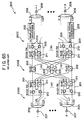
- FIG. 1 is a block diagram showing a first type (Type-1) of a basic configuration of an OCCS according to an embodiment of this invention.
- the optical input switch section 3 is made up of k optical amplifiers 31-1 to 31-k each provided for each of the input ports 1-1 to 1-k, k optical demultiplexers 32-1 to 32-k each provided for each of the input ports 1-1 to 1-k, and n k ⁇ 2k optical space switch circuits 33-1 to 33-n.
- each of optical amplifiers 31-i is used properly for amplifying (compensating for) an optical level (power) of an incoming WDM signal from the input port 1-i up to an optimal level, while each of the optical demultiplexers 32-i branches the WDM signal from the corresponding optical amplifier 31-i (input port 1-i) into optical signals of wavelengths ⁇ 1 to ⁇ n.
- Each of k ⁇ 2k optical space switch circuits (each of which will hereinafter be referred to simply as a “k ⁇ 2k switch” or a “optical switch”) 33-j is for accommodating (accommodating), of the optical signals of the wavelengths ⁇ 1 to ⁇ n resulting from the branch in the k optical demultiplexers 32-i, optical signals with the same wavelength ⁇ j of k systems to route them to any one of outputs of 2k systems. That is, each of these k ⁇ 2k switches 33-j is provided in connection with each of groups each comprising identical wavelengths ⁇ j, with one k ⁇ 2k switch 33-j corresponding to one wavelength ⁇ j.
- optical multiplexing/distributing section 4 is provided between the optical input switch section 3 and the optical output switch section 5 for again wavelength-multiplexing the optical signals of the wavelengths ⁇ 1 to ⁇ n after the routing by the k ⁇ 2k switches 33-j of the optical input switch section 3 to distributively output the resultant WDM signals as input optical signals to 2k ⁇ k optical space switch circuits 51-1 to 51-n of the optical output switch section 5, which will be described below.
- this optical multiplexing/distributing section 4 is made up of 2k optical multiplexers 41 for multiplexing (n-wavelength multiplexing) the outputs of the k ⁇ 2k switches 33-j of the optical input switch section 3, and 2k 1:n optical couplers 43 for distributively outputting 2k-system WDM signals from these 2k optical multiplexers 41 as n optical signals.
- these sets of optical multiplexers 41 and the 1:n optical couplers 43 function as n:n optical multiplexing/distributing units (first multiplexing/distributing units) 40 for multiplexing (wavelength re-multiplexing) the outputs of the k ⁇ 2k switches 33-j in terms of different wavelengths ⁇ j to distributively output the resultant WDM signals as optical signals whose number is the number n of kinds of accommodation wavelengths.
- optical multiplexing/distributing section 4 is equivalent to switch groups including 2k n ⁇ n switches, which satisfies the non-blocking condition on the three-stage switch construction shown above in FIG. 64.
- Reference numeral 42 designates 2k optical amplifiers provided properly for compensating for the loss of the like of the optical power of the WDM signals after the wavelength re-multiplexing.
- the optical output switch section 5 uses switch circuits, whose number corresponds to the number n of kinds of accommodation wavelengths, for routing the input optical signals according to the identification of wavelengths to desired output ports 2-i.
- each of the 2k ⁇ k optical space switch circuits (each of which will hereinafter be referred to simply as a "2k ⁇ k switch” or an “optical switch) 51-j is for accommodating the WDM signals from the 1:n optical couplers 43 of the optical multiplexing/distributing section 4 according to the identification of output wavelengths to the output ports 2-i to rout them to any one of k-system outputs. That is, one 2k ⁇ k switch 51-j corresponds to one wavelength (output wavelength) ⁇ j to be converted.
- each of the outputs of the uppermost 2k ⁇ k switch 51-1 is connected to the wavelength ⁇ 1 line of each of the output ports 2-i, while each of the outputs of the lowermost 2k ⁇ k switch 51-n is connected to the wavelength ⁇ n line of each of the output ports 2-i.
- each of the aforesaid optical switches 33-j and 51-j is made up of two k ⁇ k optical space switch circuits 11 and k 1 ⁇ 2 optical space switch circuits 12. That is, the basic size of the optical switches (basic switch size) used in the configuration shown in FIG. 1 is k ⁇ k.
- a dedicated fixed wavelength light source not shown.
- the tunable wavelength selectors 52 function as an optical wavelength selecting section 6 for conducting wavelength selection processing whereby, of the wavelength re-multiplexed WDM signals, an optical signal with a desired input wavelength ⁇ j is outputted to a desired output port 2-i (through which it is to be outputted).
- the REGs 53 function as a first wavelength converting section 7 for converting an optical signal of an arbitrary input wavelength ⁇ j after the routing by each of the 2k ⁇ k switches 51-j into an optical signal of a desired output wavelength ⁇ j so that an optical signal with an arbitrary input wavelength ⁇ j coming in an arbitrary input port 1-i is outputted from the output port 2-i as an optical signal of a desired output wavelength ⁇ j.
- this first wavelength converting section 7 is provided in the optical output switch section 5.
- Each of the optical multiplexers 54-i is for multiplexing, in terms of n wavelengths, the optical signals wavelength-converted in the REGs 53, while each of the optical amplifiers 55-i is provided properly in order to amplifying the WDM signal from the corresponding optical multiplexer 54-i to a desired optical power.
- a WDM signal to each of the input ports 1-i is amplified up to a desired optical power in the corresponding optical amplifier 31-i, and then branched through the optical demultiplexer 32-i into optical signals of wavelengths ⁇ 1 to ⁇ n, with the optical signals from the optical demultiplexer 32-i being inputted to the first-stage n k ⁇ 2k switches 33-j according to the identification of wavelengths.
- each of the k ⁇ 2k switches 33-j routes the input optical signal ⁇ j to an arbitrary optical multiplexer 41 in the second-stage (optical multiplexing/distributing section 4) in accordance with a routing manner set in advance from the external.
- the optical multiplexer 41 again wavelength-multiplexes the optical signals from the k ⁇ 2k switches 33-j in terms of different wavelengths.
- the resultant WDM signals (2k systems) are amplified in the corresponding optical amplifiers 42 to a desired power and are distributed evenly through the 1:n optical couplers 43 to the 2k ⁇ k switches 51-j in the third-stage (optical output switch section 5).
- optical signals (WDM signals) with the same condition are inputted to the 2k ⁇ k switches 51-j in the third-stage.
- the 2k ⁇ k switches 51-j route the inputted WDM signals in the condition of the WDM signals according to the routing manner set in advance to output them to arbitrary tunable wavelength selectors (each of which will hereinafter be referred to simply as a "wavelength selector") 52.
- Each of the wavelength selectors 52 selects, from the inputted WDM signals, only an optical signal of a wavelength (wavelength to be converted and set in advance from the external) ⁇ x to be converted into a wavelength ⁇ j.
- the optical signal with the wavelength ⁇ x selected is converted into the optical signal with the wavelength ⁇ j in the corresponding REG 53 and then outputted to the optical multiplexer 54-i, where it is multiplexed together with optical signals of different wavelengths in the optical multiplexer 54-i (n-wavelength multiplexing). Thereafter, the multiplexed optical signals are amplified together in the optical amplifier 55-i (for compensating for loss) and then outputted to the output port 2-i.
- reference letters a and c to f denote individual optical signals, while paths indicated by solid lines signify paths of an optical signal of a wavelength ⁇ 1, paths indicated by thick dotted lines signify paths of an optical signal of a wavelength ⁇ 2, and paths indicated by thin dotted lines signifies an optical signal of a wavelength ⁇ n. Additionally, the optical amplifiers 31-i, 42 and 55-i are omitted from the illustration.
- this optical signal d is branched in the optical demultiplexer 32-k and then routed to the second-stage optical multiplexing/distributing section 4 through the k ⁇ 2k switch 33-1 for the wavelength ⁇ 1.
- this optical multiplexing/distributing section through the use of the n:n optical multiplexing/distributing unit 40 (the optical multiplexer 41, the 1:n optical coupler 43), evenly distributes, to all the 2k ⁇ k switches 51-j of the third-stage output optical switch section 5, the WDM signal produced by the remultiplexing with the optical signals of the other wavelengths ⁇ j.
- the aforesaid optical signal d is converted into a wavelength ⁇ n (dotted line) and sent to the output port 2-1.
- the k ⁇ 2k switch 51-n corresponding to the wavelength ⁇ n to be converted is switched to the output port 2-1 side. Additionally, if the selected wavelength ⁇ x in the wavelength selector 52 corresponding to the designated wavelength ⁇ n to the output port 2-1 is set at the original wavelength ⁇ 1 of the signal d, the optical signal of that wavelength ⁇ 1 is converted into an optical signal of the wavelength ⁇ n in the REG 53 and outputted to the output port 2-1.
- the flow of the optical signal processing in this embodiment is demultiplexing ⁇ space switching (single light) ⁇ re-multiplexing/distribution ⁇ space switching (WDM signal) ⁇ wavelength (channel) selection/wavelength conversion ⁇ wavelength multiplexing, and the output port selection operation is realized with the first-stage and third-stage switches 33-j and 51-j while the conversion operation into desired wavelengths is realized with the third-stage wavelength selectors 52 and REGs 53 (namely, the optical output switch section 5 performs both the port selection function and the routing function for desired wavelength ⁇ j).
- the branching (wavelength division) is conducted in the optical input switch section 3 and the re-multiplexing (re-editing) of optical signals of wavelengths ⁇ j is performed in the optical multiplexing/distributing section 4 and distributed in common to the optical output switch section 5 to establish an optical link with the optical output switch section 5 and even the wavelength selection/conversion is done in the optical output switch section 5.
- these sections 3 to 5 are expressed as "wavelength division type Matrix-SW section 3", "WDM shared link section 4" and “wavelength conversion Gate type Matrix-SW section 5", respectively.
- the OCCS 1 of a type performing the wavelength conversion processing in the optical output switch section 5 will sometimes be referred to hereinafter as a "composite routing (selection type wavelength conversion) type".
- the signal d is also transmitted to the output port 2-k at the wavelength ⁇ 1. That is, the signal d is broadcasted to the respective output ports 2-i at different wavelengths.
- the OCCS 1 shown in FIG. 1 additionally has a broadcast function. However, it is not complete, the broadcasting cannot be accomplished at the same wavelength ⁇ j and in the case of no existence of a idle channel (non-used wavelength) (in FIG. 9, the channel corresponding to the optical signal b in the input port 1-1 is a idle channel.).
- the sizes of all the optical switches 33-j and 51-j are determined by only the number k of ports, and the number of optical switches 33-j and 51-j is proportional to the number n of accommodation wavelengths per port. Accordingly, for the first stage of the optical routing section 2 and the third stage of the optical output switch section 5, there is no need to change the basic switch size of the optical switches 33-j and 51-j in connection with the enlargement of the communication information capacity, but optical switches having the same size can merely be used additionally in accordance with the number of added wavelengths.
- the second stage uses the n:n optical multiplexing/distributing units 40 comprising the n multiplexers 41 and 1:n optical couplers 43, even if the number n of wavelengths to be multiplexed increases as mentioned above, there is no need to use additional n:n optical multiplexing/distributing units 40 (n optical multiplexers 41 and 1:n optical couplers 43) (no need exists to change the basic configuration).
- optical multiplexers 41 and the 1:n optical couplers 43 have been put to use in the existing WDM terminal station (transmission) system for the point-to-point transmission, it can be considered that they are the existing optical parts, and it is possible to use them in constructing the OCCS 1.
- n-wavelength multiplexing technique it is possible to offer an n-wavelength accommodation OCCS 1 immediately.
- a relaying amplifying technique therefor and an 8 ⁇ 8-size optical switch it is possible to offer 1024 ⁇ 1024-size OCCS 1 immediately.
- this contributes greatly to that a large-capacity OCCS 1 is put on the market at an early stage and that a large-capacity optical network is constructed for a short time, resulting in improvement of optical communication service.
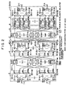
- FIG. 2 is a block diagram showing a second type (Type-2) of the basic configuration of the OCCS according to the embodiment of this invention.
- the OCCS 1 (Type-2) shown in FIG. 2 is based on the OCCS 1 (Type-1 : "composite routing (selection type wavelength conversion) type") shown in FIG. 1, but is constructed to accommodate more wavelengths.
- optical amplifiers are employed for compensating for the transmission loss.
- severe difficulty is experienced in covering all the bands through the use of one optical amplifier, and optical amplifiers dedicated to each of wavelength bands are on the development.
- an optical input switch section 3 is composed of k wavelength band demutiplexers 34-1 to 34-k each provided in connection with each of the input ports 1-i, optical amplifiers 31-1-p to 31-k-p (amounting to M ⁇ k) for the wavelength bands Band-p provided according to the input port 1-i, 1:n p optical demultiplexers 32-1-p to 32-k-p (M ⁇ k in total) for the wavelength bands Band-p provided according to the input port 1-i, and k ⁇ 2k switches 33-p-1 to 33-p-n p ( ⁇ n p in total) provided according to the number n p of kinds of accommodation wavelengths in each of wavelength bands Band-p.
- an optical multiplexing/distributing section 4 is composed of 2k n p :1 optical multiplexers 41-1-p to 41-2k-p (M ⁇ 2k in total) provided for each of the wavelength bands Band-p, optical amplifiers 42-1-p to 42-2k-p (M ⁇ 2k in total) for wavelength bands Band-p provided for the wavelength bands Band-p (2k for each of the wavelength bands), 2k wavelength band multiplexers 44-1 to 44-2k, and 2k (1: ⁇ n p ) optical couplers 43-1 to 43-2k.
- each of the wavelength band demultiplexers 34-i is for demultiplexing an input WDM signal from the input port 1-i into optical signals according to wavelength band Band-p, while each of the optical amplifiers 31-i-p is for amplifying (loss-compensating) an input optical signal to a desired power in order to compensate for the losses of the optical signals in the wavelength band Band-p after the demultiplexing by the wavelength band demultiplexers 34-i.
- each of the wavelength band multiplexers 44-r is for band-multiplexing the outputs of the optical amplifiers 42-r-p in terms of optical signals of different wavelength bands Band-p, while each of the (1: ⁇ n p ) optical couplers 43-r is for distributively outputting the output (WDM signal) of the corresponding wavelength band multiplexer according to ⁇ n p .
- the optical multiplexers 41-r-p, sets of the wavelength band multiplexers 44-r and the (1: ⁇ n p ) optical couplers 43-r function as 2k ( ⁇ n p : ⁇ n p ) multiplexing/distributing units (second multiplexing/distributing units) 40-r for multiplexing the outputs of the k ⁇ 2k switches 33-p-q in terms of different input wavelengths ⁇ pq of the same input wavelength band Band-p to band-multiplex the resultant multiplexed optical signals of the wavelength bands Band-p and then distributively output them according to the number ⁇ n p of kinds of accommodation wavelength bands.
- the 2k ⁇ k switches 51-p-q are for accommodating the outputs of the (1: ⁇ n p ) optical couplers 43-r according to output wavelength band Band-p identification and output wavelength ⁇ pq identification to the output ports 2-i to route them to any one of the k-system outputs. That is, the 2k ⁇ k switches 51-p-q are provided according to output wavelength band Band-p identification and output wavelength ⁇ pq identification, with one 2k ⁇ k switch 51-p-q corresponding to one output wavelength ⁇ pq of one output wavelength band Band-p.
- Each of the tunable wavelength selectors 52 is similar to that shown in FIG. 1, and is for selecting an optical signal of an input wavelength ⁇ pq to be converted into a desired output wavelength ⁇ pq from the WDM signals after the routing by the 2k ⁇ k switches 51-p-q, while each of the REGs 53 is for converting the wavelength ⁇ pq of the optical signal selected in the corresponding tunable wavelength selector 52 into the desired output wavelength ⁇ pq.
- the aforesaid tunable wavelength selectors 53 function as an optical wavelength selecting section 6 as in the case described above with reference to FIG. 1, and the REGs 53 function as a first wavelength converting section 7 as in the case described above with reference to FIG. 1.
- this first wavelength converting section 7 is placed in the optical output switch section 5 [that is, this OCCS 1 is also constructed as the "composite routing (selection type wavelength conversion) type" described above with reference to FIG. 9].
- each of the optical muliplexers 54-i-p is for multiplexing the wavelengths ⁇ p1 to ⁇ pn p pertaining to the same output wavelength band Band-p, while each of the optical amplifiers 55-i-p is for amplifying (compensating for loss) the output (WDM signal on the wavelength band Band-p) of the corresponding optical multiplexer 54-i-p to a desired power, and even each of the wavelength band multiplexers 56-i is for multiplexing the outputs of the optical amplifiers 55-i-p for different wavelength bands Band-p.
- this OCCS 1 (Type-2)
- the routing similar to that of the OCCS 1 shown in FIG. 1 can be made according to the wavelength band Band-p while the loss compensation is accomplished through the use of the dedicated optical amplifiers 31-i-p and 42-r-p according to the wavelength band Band-p.
- FIG. 3 is a block diagram showing a third type (Type-3) of the basic configuration of the OCCS according to the embodiment of this invention.
- Type-3 the OCCS 1 (Type-3) shown in FIG.
- REGs 53' are provided at the rear stages of optical demultiplexer 32-i in place of the REGs 53 of the optical output switch section 5 and, in an optical multiplexing/distributing section 4, 2k n ⁇ n coupling/demultiplexing units 40A (each comprising an n:1 optical couplers 45 and an optical demultiplexer 46 are used instead of the 2k n:n optical multiplexing/distributing units 40 (each comprising the optical multiplexer 41 and a 1:n optical coupler 42).
- each of the k ⁇ 2k switches 33-j accommodates the outputs of the REGs 53' according to the identification of k-system input wavelengths ⁇ j coming in the input ports 1-i to route them to any one of the outputs (n ⁇ n coupling/demultiplexing units 40A) of the k systems. That is, also in this configuration (Type-3), one k ⁇ 2k switch 33-j corresponds to one input wavelength ⁇ j.
- each of the n ⁇ n coupling/demultiplexing units (first coupling/demultiplexing units ) 40A is for coupling the outputs of the k ⁇ 2k switches 33-j in terms of different input wavelengths ⁇ j before the wavelength conversion and then for demltiplexing them according to the wavelength ⁇ j.
- the n ⁇ n coupling/demultiplexing units 40A include 2k n:1 optical couplers (combiners) 45 and 2k optical branching units 46.
- each of 2k ⁇ k switches 51-j is similar to that shown in FIG. 1, but in this configuration, it accommodates the outputs of the n ⁇ n coupling/demultiplexing units 40A according to the identification of output wavelengths ⁇ j to the output ports 2-i to route them to any one of the outputs of the k systems. That is, one 2k ⁇ k switches 51-j corresponds to one of the converted wavelengths (output wavelengths) ⁇ j.
- the uppermost 2k ⁇ k switches 51-1 is connected to the wavelength ⁇ 1 lines of the output ports 2-i.
- each of the WDM signals (n-wavelength multiplexed optical signals) coming in the input ports 1-i is demultiplexed into optical signals of wavelengths ⁇ 1 to ⁇ n by means of the optical demultiplexer 32-i. Additionally, the optical signals after the demultiplexing are converted through the REGs 53' into optical signals of desired output wavelengths ⁇ j and then inputted to the k ⁇ 2k switches 33-j according to the input wavelength ⁇ j identification.
- the k ⁇ 2k switches 33-j route the optical signals with the same input wavelength ⁇ j to the arbitrary n ⁇ n coupling/demultiplexing units 40A in the second stage (optical multiplexing/distributing section 4).
- the n ⁇ n coupling/demultiplexing units 40A concentrate the outputs of the k ⁇ 2k switches 33-j in terms of the different input wavelengths ⁇ 1 to ⁇ n before the wavelength conversion and then couple (re-multiplexing) them in the n:1 optical couplers 45 and subsequently re-branches them in the optical demultiplexers 46, thereafter routing to 2k ⁇ k switches 51-j in the third stage (optical output switch section 5) according to output wavelength ⁇ j.
- the optical demultiplexers 46 are made to select, of the WDM signals re-multiplexed in the n:1 optical couplers 45, optical signals of desired output wavelengths ⁇ j to the 2k ⁇ k switches 51-j.
- the 2k ⁇ k switches 51-j concentrate the optical signals from the n ⁇ n coupling/demultiplexing units 40A in units of output wavelength ⁇ j identification and route these optical signals to the arbitrary output ports 2-i (optical multiplexers 54-i).
- the optical signals routed is multiplexed together with optical signals of other output wavelengths ⁇ j in the optical multiplexers 54-i and outputted from the output ports 2-i.
- optical signals of input wavelengths ⁇ j are converted into optical signals of desired output wavelengths ⁇ j in advance and then routed, and through the use of the optical demultiplexers 46 and the optical multiplexers 54-i, the unnecessary wavelengths ⁇ j to the output ports 2-i are moved from the WDM signals after the coupling by the optical couplers 45 , thereby selecting the desired output wavelengths ⁇ j.
- the numbers of the optical switches 33-j and 51-j are proportional to the number n of accommodation wavelengths per port, and, for the first stage (the optical routing section 2) and the third stage (the optical output switch section 5), there is no need to change the basic switch size of the optical switches 33-j and 51-j in connection with the enlargement of the communication information capacity, but optical switches having the same size can merely be used additionally in accordance with the number of added wavelengths.
- the second stage uses the n ⁇ n optical coupling/demultiplexing units 40A each comprising the n:1 optical couplers 45 and the optical demultiplexer 46, even if the number n of wavelengths to be multiplexed increases as mentioned above, there is no need to use additional n ⁇ n optical coupling/demultiplexing units 40A (n:1 optical couplers 45 and the optical demultiplexers 46) (no need exists to change the basic configuration).
- n:1 optical couplers 45 and the optical demultiplexers 46 have been put to use in the existing WDM terminal station (transmission) system for the point-to-point transmission, that is, since they are the existing optical parts, it is possible to use them in constructing the OCCS 1.
- the wavelength selection processing is achievable with one stage of the optical multiplexing/distributing section 4 and the optical output switch section 5. That is, for example, if the optical multiplexers 54-i have a sufficient wavelength demultiplexing characteristic, the optical demultiplexers 46 are replaceable with the 1:n optical couplers (distributors) 43 shown in FIG. 1, respectively. On the other hand, if the optical demultiplexers 46 have a sufficient wavelength demultiplexing characteristic, the optical multiplexers 54-i are replaceable with the optical couplers 45, respectively.
- FIG. 10 For example, in the former case, that is, in the case in which the optical demultiplexers 46 are replaced with the 1:n optical couplers 43, respectively, the operation is as shown in FIG. 10.
- reference letters a to f denote individual optical signals, while paths indicated by solid lines signify paths of an optical signal of a wavelength ⁇ 1, paths indicated by thick dotted lines signify paths of an optical signal of a wavelength ⁇ 2, and paths indicated by thin dotted lines signifies an optical signal of a wavelength ⁇ n.
- the optical amplifiers 31-i, 42 and 55-i are omitted from the illustration.
- this optical signal f (wavelength ⁇ n : thin dotted line) to the input port 1-k for instance, this optical signal f is branched in the optical demultiplexer 32-k of the optical input switch section 3 and then is inputted to the REG 53' corresponding to the wavelength ⁇ n, where, assuming that the wavelength ⁇ n is made to be converted into the wavelength ⁇ 2, the optical signal of the wavelength ⁇ n is converted into an optical signal of the wavelength ⁇ 2 and then is branched and outputted to the output terminal for the wavelength ⁇ 2.
- the optical signal after the wavelength conversion is routed to the second-stage optical multiplexing/distributing section 4 through the k ⁇ 2k switch 33-2 corresponding to the input wavelength ⁇ 2 before the wavelength conversion to be coupled with optical signals of other wavelengths ⁇ j in the n:1 optical couplers 45, and then distributed in the form of n optical signals in the 1:n optical coupler 43 to be evenly given distributively to all the 2k ⁇ k switches 51-j in the output optical switch section 5.
- the aforesaid optical signal f is transmitted to the output port 2-1.
- the k ⁇ 2k switch 51-2 corresponding to the wavelength ⁇ 2 after the conversion is switched to the output port 2-1 (optical multiplexer 54-2) side; whereupon, the aforesaid optical signal f is automatically inputted to the wavelength ⁇ 2 input terminal of the optical multiplexer 54-2, so the optical signals of the unnecessary wavelengths ⁇ j (channels) other than the wavelength ⁇ 2 are naturally removed, thereby selecting only the optical signal of the wavelength ⁇ 2.
- the flow of the optical signal processing in this configuration is branching ⁇ wavelength conversion/branching ⁇ space switching (single light) ⁇ coupling (re-multiplexing)/distribution ⁇ space switching (WDM signal) ⁇ wavelength (channel) selection/multiplexing, and the output port selection operation is realized with the first-stage and third-stage switches 33-j and 51-j while the conversion operation into desired wavelengths ⁇ j is realized with the REGs 53' in the first stage and the optical multiplexers 54-i in the third stage (namely, the optical output switch section 5 performs both the port selection function and the routing function for designated wavelength ⁇ j).
- the wavelength conversion/branching are conducted in the optical input switch section 3 and the coupling (re-editing) of optical signals of wavelengths ⁇ j is performed in the optical multiplexing/distributing section 4 and distributed in common to the optical output switch section 5 to establish an optical link with the optical output switch section 5 and even the multiplexing (wavelength multiplexing) is done in the optical output switch section 5.
- these sections 3 to 5 are expressed as "wavelength conversion gate type Matrix-SW section 3", "WDM shared link section 4" and “wavelength multiplexing type Matrix-SW section 5", respectively.
- the OCCS 1 of a type performing the wavelength conversion processing in the optical input switch section 3 will sometimes be referred to hereinafter as a "composite routing (branching type wavelength conversion) type".
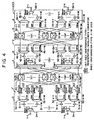
- Fig. 4 is a block diagram showing a fourth type (Type-4) of the basic configuration of the OCCS according to the embodiment of this invention.
- the OCCS 1 (Type-4) shown in FIG. 4 involves the configuration (Type-3 : "composite routing (branching type wavelength conversion” type) described above with reference to FIG. 3, and is designed to accommodate more wavelengths, as well as the configuration (Type-2) described above with reference to FIG. 2.
- the second stage includes 2k ( ⁇ n p :1) optical couplers (combiners) 45-1 to 45-2k, 2k wavelength band demultiplexers 47-1 to 47-2k, optical amplifiers 42-1-p to 42-2k-p (M ⁇ 2k in total) for wavelength bands Band-p, provided 2k for the wavelength bands Band-p (2k for each of the wavelength bands), and optical demultiplexers 46-1-p to 46-2k-p (M ⁇ 2k in total) provided for wavelength bands Band-p (2k for each of the wavelength bands).
- the third stage includes, as in FIG. 2, 2k ⁇ k switches 51-p-q ( ⁇ n p in total), optical multiplexers 54-i-p (M ⁇ k in total) for wavelength bands Band-p, optical amplifiers (M ⁇ k in total) for the wavelength bands Band-p and k wavelength band multiplexers 56-i each provided in connection with each of the output ports 2-i.
- each of the REGs 53' is for converting an optical signal of each of the wavelengths ⁇ pq branched in the optical demultiplexer 32-i-p into a desired output wavelength ⁇ pq through the use of a non-shown variable wavelength light source also in this case. Therefore, the k ⁇ 2k switches 33-p-q concentrate (accommodate) the outputs of the REGs 53' according to the input wavelength band Band-p identification and the input wavelength ⁇ pq identification before the wavelength conversion to route them to any one of the outputs (optical couplers 45-1 to 45-2k) of the 2k systems. That is, one k ⁇ 2k switch 33-p-q corresponds to one wavelength ⁇ pq of one wavelength band Band-p before the wavelength conversion by the REGs 53'.
- Each of the optical amplifiers 42-r-p is for amplifying (loss compensation) each of the optical signals of the output wavelength bands Band-p obtained by the band-demultiplexing in the wavelength band demultiplexers 47-r, while each of the optical demultiplexers 46-r-p is for branching the optical signal of the output wavelength band Band-p from the corresponding optical amplifier 42-r-p into the optical signals of the output wavelengths ⁇ pq.
- the sets of the optical couplers 45-r, the wavelength band demultiplexers 47-r and the optical demultiplexers 46-r-p function as ( ⁇ n p ⁇ n p ) coupling/demultiplexing units (second coupling/demultiplexing unit) 40A-r for wavelength-coupling the outputs of the k ⁇ 2k switches 33-p-q, demultiplexing them into optical signals of the wavelength bands Band-p and branching the optical signals of the wavelength bands Band-p after the demultiplexing in units of wavelength.
- the 2k ⁇ k switches 51-p-q accommodate the outputs of the optical demultiplexers 46-r-p according to output wavelength band Band-p identification and output wavelength ⁇ pq identification to route them to any one of the outputs of the k systems. That is, also in this case, one 2k ⁇ k switch 51-p-q corresponds to one output wavelength ⁇ pq of one output wavelength band Band-p.
- the optical demultiplexers 46-r-p and the optical demultiplexers 54-i-p constitute the optical wavelength selecting section 6, while the REGs 53' organizes the second wavelength converting section 7'.
- this OCCS 1(Type-4) also can demulitiplex the WDM signals coming in the input ports 1-i in units of wavelength band Band-p in the wavelength band demultiplexers 34-i and then conduct the routing similar to that of the OCCS 1 (Type-3), shown in FIG. 3, in units of wavelength band Band-p while performing the loss compensation in units of wavelength band Band-p through the use of the dedicated optical amplifiers 31-i-p and 42-r-p.
- the optical multiplexers 54-i-p or the optical demultiplexers 46-r-p have a sufficient wavelength demultiplexing characteristic
- the optical multiplexers 54-i-p are replaceable with n p :1 optical couplers (combiners)
- the optical demultiplexers 46-r-p are replaceable with 1: n p optical couplers (distributors) so that the wavelength selection processing is made in one stage: either in the optical multiplexing/distributing section 4 or in the optical output switch section 5.
- this OCCS 1 (Type-4) falls under the "composite Routing (branching type wavelength conversion) type" (see FIG. 10) in which the wavelength conversion processing is conducted in the optical input switch 3.
- FIG. 5 is a block diagram showing a fifth type (Type-5) of the basic configuration of the OCCS according to the embodiment of this invention.
- the OCCS 1 (Type-5) shown in FIG. 5 differs from the OCCS 1 (Type-1) shown in FIG. 1 in that the second-stage optical mulitplexing/distributing section 4 includes 2k combinations each comprising an n:n star type optical coupler 47 and a tunable wavelength selectors 48 each provided in connection with each of the outputs of this n:n star type optical coupler 47.
- Each of the n:n star type optical couplers (first coupling/distributing units) 47 is for coupling the outputs of k ⁇ 2k switches 33-j in terms of different input wavelengths ⁇ j and for distributively outputting them in form of n (the number of kinds of accommodation wavelengths) optical signals, while each of the tunable wavelength selectors (wavelength selectors) 48 is for selecting, from the n distributing outputs of the n:n star type optical coupler 47 (which may hereinafter be referred to simply to a "star coupler 47"), an optical signal of an input wavelength ⁇ j to be converted into a desired output wavelength ⁇ j.
- the wavelength selectors 48 constitute the aforesaid optical wavelength selecting section 6. Additionally, when the second-stage configuration is regarded as being equivalent to (n ⁇ n) optical switches, this satisfies the non-blocking condition in the three-stage switch network.
- the 2k ⁇ k switches 51-j accommodate the outputs of the wavelength selectors 48 according to the identification of output wavelength ⁇ j to the output ports 2-i to rout to any one of the outputs of the k systems. That is, also in this case, one 2k ⁇ k switch 51-j corresponds to one output wavelength ⁇ j.
- the uppermost 2k ⁇ k switch 51-1 is connected to the wavelength ⁇ 1 line to each of the output ports 1-i.
- the REGs 53 provided in the optical output switch section 5 constitute the aforesaid first wavelength converting section 7.
- the WDM signals (n-wavelength multiplexed optical signals) arriving at the input ports 1-i are amplified (loss-compensated) by the corresponding optical amplifiers 31-i and then demulitplexed into optical signals of wavelengths ⁇ 1 to ⁇ n by the optical demultiplexers 32-i and even inputted to the k ⁇ 2k switches 33-j according to wavelength ⁇ j, respectively.
- the k ⁇ 2k switches 33-j route the optical signals with the same wavelength ⁇ j from the optical demultiplexers 32-i to the star couplers 47 in the second stage (optical multiplexing/distributing section 4). That is, also in this case, one k ⁇ 2k switch 33-j corresponds to one wavelength ⁇ j. Subsequently, the star couplers 47 couple (re-multiplex) the optical signals from the k ⁇ 2k switches 33-j in terms of different input wavelengths ⁇ j and distributively output them as n optical signals.
- Each of the distributed outputs comes in the corresponding wavelength selectors 48 which in turn, select desired input wavelengths (wavelengths to be converted) ⁇ j and outputs them to the 2k ⁇ k switches 51-j in the third stage (optical output switch section 5).
- the 2k ⁇ k switches 51-j concentrate the outputs of the wavelength selectors 48 according to output wavelength ⁇ j identification, with one switch corresponding to one wavelength ⁇ j to be converted.
- the 2k ⁇ k switches 51-j route the optical signals of the conversion wavelengths ⁇ j, selected by the wavelength selectors 48, to the REGs 53 for the conversion output wavelengths ⁇ j.
- the optical signals of the wavelengths to be converted are converted into desired output wavelengths ⁇ j in the REGs 53 and then multiplexed together with optical signals of other wavelengths ⁇ j in the optical multiplexers 54-i, thereafter being outputted as WDM signals to the output ports 2-i.
- the OCCS 1 shown in FIG. 5 also falls under the "composite routing (selection type wavelength conversion) type" (see FIG. 9) in which the wavelength conversion processing is conducted in the optical output switch section 5.
- each of the REGs 53 is equipped with a dedicated fixed wavelength light source. Also in this configuration (Type-5), the optical amplifiers 31-i-p and 55-i-p are omissible if the WDM signal transmission loss is ignorable.
- the numbers of optical switches 33-j and 51-j are made to be proportional to the number n of accommodation wavelengths per port. Accordingly, for the first stage (the optical routing section 2) and the third stage (the optical output switch section 5), there is no need to change the basic switch size of the optical switches 33-j and 51-j in connection with the enlargement of the communication information capacity, but optical switches having the same size can merely be used additionally in accordance with the number of added wavelengths.
- the second stage uses the n:n star type optical couplers 47, even if the number n of wavelengths to be multiplexed increases as mentioned above, there is no need to use additional n:n star type optical couplers 47 (no need exists to change the basic configuration). Additionally, since the n:n star type optical couplers 47 are the existing optical parts, it is possible to use them in constructing the OCCS 1.
- FIG. 6 is a block diagram showing a sixth type (Type-6) of the basic configuration of the OCCS according to the embodiment of this invention.
- This OCCS 1 (Type-6) shown in FIG. 6 is based on the configuration (Type-5 : "composite routing (selection type wavelength conversion) type") described above with reference to FIG. 5, but is made to accommodate more wavelengths as well as the configuration (Type-2) described above with reference to FIG. 2.
- the OCCS 1 (Type-6) shown in FIG. 6 relates to a modification of the OCCS 1 (Type-2) shown in FIG. 2, as in the case of the modification of the OCCS 1 (Type-1) of FIG. 1 into the OCCS 1 (Type-5) of FIG. 5.
- the optical multiplexing/distributing section 4 includes 2k sets of ( ⁇ n p : ⁇ n p ) star type optical couplers 47' and ⁇ n p tunable wavelength selectors 48 provided at every output of ⁇ n p systems from the ( ⁇ n p : ⁇ n p ) star type optical couplers 47'.
- the ( ⁇ n p : ⁇ n p ) star type optical couplers (second coupling/distributing units) 47' are for coupling the outputs of the k ⁇ 2k switches 33-p-q in terms of different input wavelengths ⁇ pq to distributively output them in the form of ⁇ n p (total number of kinds of accommodation wavelengths) optical signals, while the wavelength selectors 48 are for selecting, from the distributed outputs from the star type optical couplers 47', optical signals of the input wavelengths (conversion wavelengths) ⁇ pq to be converted into desired output wavelengths ⁇ pq.
- the 2k ⁇ k switches 51-p-q accommodate the outputs of the wavelength selectors 48 according to output wavelength band Band-p identification and output wavelength ⁇ pq identification to the output ports 2-i and route them to any one of the outputs of the k systems.
- the wavelength selectors 48 constitute the aforesaid optical wavelength selecting section 6, while the REGs 53 of the optical output switch section 5 organize the first wavelength converting section 7.
- the WDM signals entering the input ports 1-i are demulitplexed in the wavelength band demultiplexers 34-i in units of wavelength band Band-p and, after loss-compensated for according to wavelength band Band-p through the use of the dedicated optical amplifiers 31-i-p, routed according to wavelength band Band-p as well as the OCCS 1 (Type-5) shown in FIG. 5.
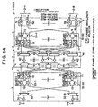
- FIG. 7 is a block diagram showing a seventh type (Type-7) of the basic configuration of the OCCS according to the embodiment of this invention.
- the OCCS 1 (Type-7) shown in FIG. 7 relates to a modification of the configuration (Type-3) shown in FIG. 3, and as compared with the configuration of FIG. 3, the 2k n ⁇ n coupling/demultiplexing units 40A in the second stage (optical multiplexing/distributing section 4) shown in FIG. 3 are replaced with sets of n:n star type optical couplers 47, similar to those described above with reference to FIG. 5, and n tunable wavelength selectors 48 provided in connection with each of the n:n star type optical couplers 47.
- the tunable wavelength selectors 48 constitute the aforesaid optical wavelength selecting section 6, while the REGs 53' organize the second wavelength converting section 7' placed in the optical input switch section 3.
- each of the WDM signals (n-wavelength multiplexed optical signals) arriving at the input ports 1-i is amplified (loss compensation) by the corresponding optical amplifier 31-i and then demultiplexed into optical signals of wavelengths ⁇ 1 to ⁇ n by the corresponding optical demultiplexer 32-i.
- the optical signals of the wavelengths ⁇ j are converted into desired conversion output wavelengths ⁇ j by the corresponding REGs 53' and then inputted to the k ⁇ 2k switches 33-j provided at every input wavelength ⁇ j before the wavelength conversion.
- the k ⁇ 2k switches 33-j route the optical signals inputted therein to the arbitrary star couplers 47 in the second stage. That is, also in this case, one k ⁇ 2k switch 33-j corresponds to one input wavelength ⁇ j before the wavelength conversion.
- the star couplers 47 couple the optical signals, routed by the k ⁇ 2k switches 33-j, in units of different wavelengths and then distributively output them as n optical signals.
- the corresponding wavelength selectors 48 select the output wavelengths ⁇ j after the wavelength conversion from the distributed outputs, then routing the 2k ⁇ k switches 51-j in the third stage.
- the 2k ⁇ k switches 51-j in the third stage concentrate the optical signals of the same wavelength ⁇ j from the wavelength selectors 48. That is, also in this case, one 2k ⁇ k switch 51-j corresponds to one output wavelength ⁇ j after the wavelength conversion.
- the 2k ⁇ k switch 51-1 is connected to the wavelength ⁇ 1 line to each of the output ports 2-i. Hence, the 2k ⁇ k switch 51-1 routes an optical signal of a desired wavelength ⁇ j after the wavelength conversion to a desired output port 2-i.
- the numbers of optical switches 33-j and 51-j are designed to be in proportion to the number n of accommodation wavelengths per port. Accordingly, for the first stage of the optical routing section 2 and the third stage of the optical output switch section 5, there is no need to change the basic switch size of the optical switches 33-j and 51-j in connection with the enlargement of the communication information capacity, but optical switches having the same size can merely be used additionally in accordance with the number of added wavelengths.
- the second stage uses the n:n star type optical couplers 47, even if the number n of wavelengths to be multiplexed increases as mentioned above, there is no need to use additional n:n star type optical couplers 47 (no need exists to change the basic configuration). Additionally, since the n:n star type optical couplers 47 are the existing optical parts, it is possible to use them in constructing the OCCS 1.
- the wavelength selection processing is achievable with one stage of the optical multiplexing/distributing section 4 and the optical output switch section 5 in a state where the wavelength selectors 48 are omitted or the optical mulitplexers 54-i are replaced with the n:1 optical couplers 45 shown in FIG. 3. That is, this OOCS 1 (Type-7) also falls under the "composite routing (branching type wavelength conversion) type" (see FIG. 10) in which the wavelength conversion processing is conducted in the optical input switch section 3.
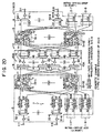
- Fig. 8 is a block diagram showing an eighth type (Type-8) of the basic configuration of the OCCS according to the embodiment of this invention.
- This OCCS 1 (Type-8) shown in FIG. 8 is based on the configuration (Type-7) described above with reference to FIG. 7, and is designed to accommodate more wavelengths, as in the case of the above-described configuration (Type-2) described above with reference to FIG. 2.
- the OCCS 1 (Type-8) shown in FIG. 8 relates to a modification of the OCCS 1 (Type-4) shown in FIG. 4 as in the modification of the OCCS 1 (Type-3) shown in FIG. 3 into the OCCS 1 (Type-7) shown in FIG. 7, and differs from the configuration shown in FIG.
- the ( ⁇ n p : ⁇ n p ) star type optical couplers (fourth coupling/distributing units) 47' are for coupling the outputs of the k ⁇ 2k switches 33-p-q in terms of different input wavelengths ⁇ pq before the wavelength conversion to distributively output them as ⁇ n p (total number of kinds of accommodation wavelengths) optical signals, while the wavelength selectors 48 are for selecting, from the distributed outputs of the star type optical couplers 47', optical signals of input wavelengths (conversion wavelengths) ⁇ pq to be converted into desired output wavelengths.
- the 2k ⁇ k switches 51-p-q in the optical output switch section 5 accommodate the outputs of the wavelength selectors 48 according to output wavelength band Band-p identification and output wavelength ⁇ pq identification to the output ports 2-i to route them to any one of the outputs of the k systems.
- the aforesaid star type optical couplers 47' constitute a optical wavelength selecting section 6, while the REGs 53' in the optical input switch section 3 organize a second wavelength converting section 7'.
- this OCCS 1 (Type-8) also can demultiplex the WDM signals arriving at the input ports 1-i according to wavelength band Band-p in the wavelength band demultiplexers 34-i and conduct routing, similar to that of the OCCS 1 (Type-7) shown in FIG. 7, according to wavelength band Band-p in a state where the loss compensation is accomplished according to the wavelength band Band-p through the use of the dedicated optical amplifiers 31-i-p.
- the wavelength selection processing is also achievable with one stage of the optical multiplexing/distributing section 4 and the optical output switch section 5 in a state where the wavelength selectors 48 are omitted or the optical mulitplexers 54-i-p are replaced with the n p :1 optical couplers (combiners).
- this OCCS 1 (Type-8) also falls under the "composite routing (branching type wavelength conversion) type" (see FIG. 10) in which the wavelength conversion processing is conducted in the optical input switch section 3.
- each of the REGs 53 is constructed as a regeneration type wavelength converter performing bit rate dependence type optical-electrical conversion (O/E) - electrical-optical conversion (E/O) (which will sometimes be referred to hereinafter as "O/E/O 53").
- O/E optical-electrical conversion
- E/O 53 electrical-optical conversion
- the OCCS 1 (Type-1 : first modification) shown in FIG. 11 is such that each of all the ports 1-1 to 1-8 and 2-1 to 2-8 is used as an inter-office transmission dedicated port which accommodates a 32-wavelength multiplexed optical signal, and the OCCS 1 with this configuration is used as the so-called "router dedicated node" in optical networks.
- a 64:1 optical multiplexer is used as each of the optical multiplexers 41 while a 1:64 optical coupler is used as each of the optical couplers 43 (no enlargement is necessary).
- a 64:1 optical multiplexer is used as each of the optical multiplexers 41 while a 1:64 optical coupler is used as each of the optical couplers 43 (no enlargement is necessary).
- OCCSs 1 which will be described herein later, it is possible to similarly cope with the increase in number of accommodation wavelengths without changing the basic switch size.
- the OCCS 1 (Type-1 : second modification) has a construction in which, of the input ports 1-1 to 1-8 and the output ports 2-1 to 2-8, six input ports and six output ports (ports 1-1 to 1-6 and 2-1 to 2-6) are used as inter-office transmission dedicated ports for accommodating a 32-wavelength multiplexed optical signal, while the remaining ports (two input ports and two output ports) (that is, ports 1-7, 1-8, 2-7 and 2-8) are allocated to intra-office interface (add/drop) ports.
- This configuration is equivalent to a configuration of an OCCS for generally standardized inter-office/intra-office transmission (which also will be referred to hereinafter as a "standardized OCCS).
- the wavelength converters 53 and the optical multiplexers 54-7 and 54-8 are removed in conjunction with the output ports 2-7 and 2-8 allocated for the intra-office interface, while the optical signals of the desired wavelength ⁇ j are selected by the remaining tunable wavelength selectors 52 to be branched (dropped).
- the input ports 1-1 to 1-6 forming a portion of the input ports 1-1 to 1-8 accommodate a 32-wavelength multiplexed optical signal produced by multiplexing 32 kinds of input wavelengths ⁇ 1 to ⁇ 32, while the remaining input ports 1-7 and 1-8 are used for adding of optical signals of 32 kinds of wavelengths ⁇ 1 to ⁇ 32.
- the output ports 2-1 to 2-6 forming a portion of the output ports 2-1 to 2-8 accommodate a 32-wavelength multiplexed optical signal produced by wavelength-multiplexing optical signals of 32 kinds of output wavelengths ⁇ 1 to ⁇ 32, while the remaining output ports 2-7 and 2-8 are used for the dropping of optical signals of 32 kinds of wavelengths ⁇ 1 to ⁇ 32.
- the number of ports to be allocated for the intra-office interface can assume a value other than above-mentioned value.
- the optical demultiplexers 32-1 to 32-8 (the optical amplifiers 31-1 to 31-8) are removed with respect to all the input ports 1-1 to 1-8, while, as in the case shown in FIG. 12, the wavelength converters 53A are mounted instead so that, in connection with all the input ports 1-1 to 1-8, adding optical signals of arbitrary wavelengths ⁇ 0 are converted into predetermined wavelengths ⁇ j and then sent to the optical routing section 2. Namely, only the output ports 2-1 to 2-8 are made to accommodate the 32-wavelength multiplexed optical signal.
- this OCCS 1 (Type-1 : third modification), in a distribution type optical network in which transmission is made from one basic point to a plurality of points, adds an optical signal of an arbitrary wavelength ⁇ 0 into a idle channel of an arbitrary one of the input ports 1-1 to 1-8, and converts that optical signal into an optical signal with a desired wavelength ⁇ j and sends it from a desired one of the output ports 2-1 to 2-8 (that is, it can be used for a point-to-multipoint type WDM transmission terminal station).
- the wavelength converters 53 and the optical multiplexers 54-1 to 54-8 are removed with respect to all the output ports 2-1 to 2-8, and each of only the input ports 1-1 to 1-8 is made to accommodate a 32-wavelength multiplexed optical signal.
- this OCCS (Type-1 : fourth modification), in a distribution type optical network in which transmission is made from a plurality of points to one basic point, can select an optical signal of a desired wavelength ⁇ 0 from arbitrary idle channels of arbitrary input ports 1-1 to 1-8 and receive it (that is, it can be used for a multipoint-to-point type WDM reception terminal station).
- the OCCS 1 As described above, according to this embodiment, it is possible to very easily realize and offer an OCCS 1 suitable for a desired application mode.
- the OCCSs 1 (Type-1 : first to fourth modifications) having the above-described configurations are used properly, in various applications, it is possible to construct optical networks meeting the user's needs.
- the OCCS 1 (Type-5) shown in FIG. 5 can four kinds of configurations similar to those described above.
- the OCCS 1 can assume four kinds of configurations: a "router dedicated configuration (first modification)", a “standardized configuration (second modification)", a “ configuration for point-to-multipoint type WDM transmission terminal station (third modification)", and a “configuration for multipoint-to-point type WDM reception terminal station (fourth modification)", thus permitting the constructions of optical networks meeting the user's needs in various applications.
- the OCCS 1 (Type-6) shown in FIG. 6 also can take four kinds of configurations similar thereto.
- each of the REGs 53' is constructed as a bit rate independence type O/E/O.
- the same or corresponding components as or to those in FIG. 3 are marked with the same reference numerals as those in FIG. 3, and the description thereof will be omitted for simplicity.
- each of all the ports 1-1 to 1-8 and 2-1 to 2-8 is designed to be used as an inter-office transmission dedicated port which accommodates a 32-wavelength multiplexed optical signal, and also in this case, it is used as a "node dedicated to a router".
- the optical demultiplexers 32-7 and 32-8 (the optical amplifiers 31-7 and 31-8) are removed with respect to the input ports 1-7 and 1-8 allocated for the intra-office interface, while wavelength converting units (O/E/O) 53A for 32 wavelengths, having fixed wavelength light sources of wavelengths ⁇ 1 to ⁇ 32, are mounted instead, thus converting an adding optical signal of an arbitrary wavelength ⁇ 0 into an optical signal with a predetermined wavelength ⁇ j and sending it to the optical routing section 2.
- optical multiplexers 54-7 and 54-8 are removed with respect to the output ports 2-7 and 2-8 allocated for the intra-office interface so that optical signals of desired wavelengths ⁇ j can be branched (dropped) after the routing by the optical switches 51-j.
- the number of ports to be allocated for the intra-office interface can assume a value other than the above-mentioned value.
- the optical demultiplexers 32-1 to 32-8 (the optical amplifiers 31-1 to 31-8) are removed with respect to all the input ports 1-1 to 1-8 so that, in connection with all the input ports, the remaining wavelength converters 53' convert adding optical signals of arbitrary wavelengths ⁇ 0 into optical signals of predetermined wavelengths ⁇ j and send them to the optical routing section 2. That is, each of the output ports 2-1 to 2-8 only accommodate the 32-wavelength multiplexed optical signal.
- this OCCS 1 (Type-3 : third modification), in the distribution type optical networks in which transmission is made from one basic point to a plurality of points, also can add an optical signal with an arbitrary wavelength ⁇ 0 into a idle channel of the arbitrary input ports 1-1 to 1-8 to convert that optical signal into an optical signal of a desired wavelength ⁇ j, and send it through the desired output port 2-1 to 2-8 (that is, it can be used for a point-to-multipoint type WDM transmission terminal station).
- the optical multiplexers 54-1 to 54-8 (the optical amplifiers 55-1 to 55-8) are removed with respect to all the output ports 2-1 to 2-8, thereby branching the optical signals of arbitrary wavelengths ⁇ j after the routing by the optical switches 51-1 to 51-8.
- this OCCS 1 (Type-3 : fourth modification), in the distribution type optical networks in which transmission is made from a plurality of points to one basic point, also can convert optical signals from arbitrary input ports 1-1 to 1-8 into desired wavelengths ⁇ j and receive them from arbitrary idle channel (that is, it can be used for a multipoint-to-point type WDM reception terminal station).
- OCCSs 1 (Type-3 : first to fourth modifications) thus constructed, it is also possible to construct optical networks meeting the user's needs in various applications.
- the OCCS 1 (Type-7) can also take four kinds of configurations similar to those described above.
- the OCCS 1 (Type-4) can assume four kinds of configurations: a "router dedicated configuration (first modification)", a “standardized configuration (second modification)", a “configuration for point-to-multipoint type WDM transmission terminal station (third modification)", and a “configuration for multipoint-to-point type WDM reception terminal station (fourth modification)", thus permitting the constructions of optical networks meeting the user's needs in various applications. Additionally, the OCCS 1 (Type-8) shown in FIG. 8 also can take four kinds of configurations similar thereto.
- Type-1 the basic configuration shown in FIG. 1
- OADM Optical Add Drop Multiplexer
- the optical switches 33-j and the optical switches 51-j are constructed as 2 ⁇ 4 switches and 4 ⁇ 2 switches 12, respectively, each of which basically comprises a 2 ⁇ 2 switch 11 and a 1 ⁇ 2 switch 12. Furthermore, also in this case, each of the wavelength converters 53 shown in FIG.1 is constructed as a bit rate independence type O/E/O in FIGs. 27 to 30.
- the operation of the OADM (Type-1) 1 shown in FIG. 27 is similar to that of the OCCS 1 (Type-1) shown in FIG. 1
- the operation of the OADM (Type-2) 1 shown in FIG. 28 is similar to that of the OCCS 1 (Type-2) shown in FIG. 2
- the operation of the OADM (Type-3) shown in FIG. 29 is similar to that of the OCCS 1 (Type-3) shown in FIG. 3
- the operation of the OADM (Type-4) shown in FIG. 30 is similar to that of the OCCS 1 (Type-4) shown in FIG. 4. Accordingly, any type of the OADM 1 can cope with an increase in number of accommodation wavelengths without changing the basic switch size.
- the OADM 1 based on the OCCS 1 differs from the existing OADM in having a wavelength conversion function in addition to an optical signal add/drop function, so that the add/drop of an optical signal with an arbitrary wavelength ⁇ j becomes possible, thus flexibly handling the needs on network constructions.
- this OADM 1 is applicable, for example, to a case in which ring networks existing independently are connected to each other.
- the OADMs 1 described above can also be constructed on the basis of the OCCS 1 shown in FIGs. 5 to 8.
- FIG. 31 shows, point-to-multipoint type (Type-s : third modification) and multipoint-to-point type (Type-s : fourth modification) OCCSs 1, indicated at reference numerals 13 and 14, are installed in communication basic point cities lying the West and the East, and standardized (Type-s : second modification) OCCSs 1 or OADMs 1 (Type-s) are located in relaying point cities lying therebetween. Additionally, router type OCCSs 1 are situated on the sea where no communication demand exists.
- OCCSs OCCSs
- WDMs WDM transmission apparatus
- the optical network shown in FIG. 31 is equipped with at least one OCCS 1 and this OCCS 1 is constructed as any one of the various types of OCCSs 1 (Type-s : first to fourth modifications).
- this OCCS 1 is constructed as any one of the various types of OCCSs 1 (Type-s : first to fourth modifications).
- OCCSs 1 any one of the various types of OCCSs 1 (Type-s : first to fourth modifications).
- Type-s first to fourth modifications.
- a mesh-like optical network is constructed by using one point-to-multipoint type (Type-s : third modification) or multipoint-to-point type (Type-s : fourth modification) OCCS 1 and by using the existing WDM transmission apparatus as other OCCSs or the like, since various alternative routes can be set in preparation for occurrence of troubles, it is possible to construct a high-reliability optical network.
- FIG. 32 is a block diagram showing an OCCS (first mode) according to a second concrete example of this invention.
- This OCCS 1 is made up of an input regeneration section 7A, a routing section 8a and an output regeneration section 7B.
- sub-port wavelength converting sections fixed wavelength converting sections 7A-1 to 7A-32 are provided, each of which comprises four (fixed) wavelength converters (REGs) 71 for converting four kinds of input wavelengths into the same intra-apparatus wavelength ⁇ r.
- REGs fixed wavelength converters
- This decreases the number of wavelengths to be handled in the apparatus to 32/128 1/4.
- the wavelength converter 71 for ⁇ 1 is omissible.
- the routing section 8a is for routing, to desired output ports 2-i, the optical signals wavelength-converted into four sets of 32 intra-apparatus wavelengths ⁇ 1 to ⁇ 32 in the input regeneration section 7A as mentioned above.
- the existence of the four sets of intra-apparatus wavelengths ⁇ 1 to ⁇ 32 requires the routing conducted to prevent the optical signals with the same wavelength ⁇ r from colliding with each other.
- the "optical space switch circuit” is referred to simply as “switch” or "optical switch".
- optical signals of the input wavelength ⁇ 1 coming in the input ports 1-1 to 1-8 are concentrated, while in the 8 ⁇ 16 switch 33-2, the optical signals of the input wavelength ⁇ 2 coming in the input ports 1-1 to 1-8 are concentrated.
- optical signals of the input wavelength ⁇ 128 coming in the input ports 1-1 to 1-8 are concentrated. The concentrated optical signals are routed to any one of the 16 outputs.
- each of the 32:1 multiplexers 81-1 to 81-4 concentrates each (different intra-apparatus wavelengths ⁇ 1 to ⁇ 32) of sets of the outputs (switch ports #1 to #128; four sets of intra-apparatus wavelengths ⁇ 1 to ⁇ 32) of the 8 ⁇ 16 switch 33-j and multiplexes (wavelength-multiplexes), while each of the 1:128 couplers 82-1 to 82-4 distributes the output (32 WDM signal) of the corresponding one of the 32:1 multiplexers 81-1 to 81-4 in the form of 128 optical signals.
- the aforesaid 4 ⁇ 1 (p ⁇ 1) switches 83-1 to 83-128 concentrate one outputs (32-WDM signals) of the 4 ⁇ 128 systems from the 1:128 (1:n) couplers 82-1 to 82-4, namely, each concentrating four outputs in total, for selecting any one of these four sets of 32-WDM signals under the control of an apparatus control section 9.
- the aforesaid apparatus control section 9 not only controls the 4 ⁇ 1 switches 83-1 to 83-128 and the tunable wavelength selectors 84, but also performs the control of the routing to the 8 ⁇ 16 switches 33-j and the 16 ⁇ 8 switches 51-j and the control needed for the entire apparatus.
- the 16 ⁇ 8 switches 51-j concentrate the outputs (optical signals of intra-apparatus wavelengths ⁇ x) of the 128 ⁇ 128 routing sections 8A-1 to 8A-16 in units of intra-apparatus wavelengths (converted wavelengths) to be converted into the same output wavelength ⁇ j, and send them to desired routes (namely, desired output ports 2-i) of the 8 outputs (routes). That is, one 16 ⁇ 8 switch 51-j corresponds to one converted wavelength (output wavelength) ⁇ j. For example, in FIG. 32, the uppermost 16 ⁇ 8 switch 51-1 is connected to the output wavelength line to each of the output ports 2-i, while the lowermost 16 ⁇ 8 switch 51-128 is connected to the output wavelength ⁇ 128 line to each of the output ports 2-i.
- the routing section 8a functions as a wavelength multiplexing/distribution routing section for wavelength-multiplexing the optical signals of the intra-apparatus wavelengths ⁇ 1 to ⁇ 32 from the input regeneration section 7A to dristributively route the resultant 32-WDM signals (intra-apparatus wavelength multiplexed optical signals) to the desired output ports 2-i as optical signals including desired output wavelengths ⁇ j, while the tunable wavelength selectors 84 constitute an optical wavelength selecting section which selects optical signals of desired intra-apparatus wavelengths ⁇ r from the 32-WDM signals.
- the optical signals of 128 wavelengths received through the input ports 1-i are converted by four wavelengths into the same wavelength ⁇ r in the wavelength converters 71 of the input regeneration section 7A as mentioned above to be converted into 32-intra-apparatus-wavelengths ⁇ 1 to ⁇ 32 (four sets).
- These optical signals of four sets of intra-apparatus wavelengths ⁇ 1 to ⁇ 32 are concentrated in the 8 ⁇ 16 switches 33-1 to 33-128 according to input wavelength ⁇ j before the wavelength conversion so that the identical intra-apparatus wavelengths ⁇ r do not collide with each other, and routed to arbitrary idle outputs (routes) of the 16 outputs.
- the four sets of optical signals of intra-apparatus wavelengths ⁇ 1 to ⁇ 32 are inputted to the 128 ⁇ 128 routing sections 8A-1 to 8A-16.
- the 128 ⁇ 128 routing sections 8A-1 to 8A-16 divide the optical signals of the intra-apparatus wavelengths ⁇ 1 to ⁇ 32 inputted from the 8 ⁇ 16 switches 33-1 to 33-128 into four groups according to adjacent 32 wavelengths, which in turn, are 32-wavelength-multiplexed in the 32:1 multiplexers 81-1 to 81-4, respectively.
- the outputs (32-WDM signals) thereof are 128-distributed through the 1:128 couplers 82-1 to 82-4 to the 4 ⁇ 1 switches 83-1 to 83-128.
- each of the tunable wavelength selectors 84 receives the optical signals of the intra-apparatus wavelengths ⁇ 1 to ⁇ 32, it is possible to considerably relieve the wavelength area to be covered by the tunable wavelength selectors 84 or the transmission band characteristics of by the tunable wavelength selectors 84.
- the interval between the adjacent wavelengths is 0.8 nm
- the wavelength area in the case of 128 waves becomes above 100 nm (see FIG. 56A)
- the wavelength area in the case of 32 waves ( ⁇ 1 to ⁇ 32) decreases to 25.6 nm (see FIG. 56B or 56C). This means that the wavelength area can be cut up to approximately 1/4 of that in the case of 128 waves.
- incontinuous wavelength-grid wavelengths are allocated as the intra-apparatus wavelengths ⁇ 1 to ⁇ 32, it is possible to relieve the transmission band characteristic of the tunable wavelength selectors 84.
- the wavelength-grid wavelengths are alternately allocated at a wavelength interval of 1.6 nm as the intra-apparatus wavelengths ⁇ 1 to ⁇ 32 as shown in FIG. 57B, the transmission band of the tunable wavelength selectors 84 can be relieved from 0.8 nm (see FIG. 57A) to 1.6 nm in the case of 128 waves.
- FIG. 57C shows, if the wavelength grids are allocated for the intra-apparatus wavelengths ⁇ 1 to ⁇ 32 to use a wavelength area (> 100 nm) approximately equal to that in the case of 128 waves, the transmission band of the tunable wavelength selectors 84 can be relieved from 0.8 nm in the case of 128 waves to 3.2 nm.
- the allocation of the wavelength grids to the intra-apparatus wavelengths ⁇ 1 to ⁇ 32 is the same also in other modes which will be described herein after.
- the optical signals of the intra-apparatus wavelengths ⁇ x selected as mentioned above are inputted to the 16 ⁇ 8 switches 51-1 to 51-128 according to converted output wavelength ⁇ j and routed to desired outputs of the 8 outputs to be inputted to the wavelength converters 72 of the output regeneration section 7B.
- the wavelength converters 72 convert the inputted optical signals of the intra-apparatus wavelengths ⁇ x into optical signals of predetermined output wavelengths ⁇ j and then output them to the output transmission lines 2-i.
- the input regeneration section 7A converts optical signals of 128 waves ( ⁇ 1 to ⁇ 128) from the input transmission lines 1-i into optical signals of 32 intra-apparatus wavelengths ⁇ 1 to ⁇ 32 to decrease the number of wavelengths to be handled in the apparatus, and the routing section 8a conducts the wavelength multiplexing/distribution routing so that the optical signals with the same intra-apparatus wavelength do not collide with each other. Therefore, as described above, it is possible to considerably relieve the given band characteristics (effective wavelength area, transmission band characteristic and wavelength demultiplexing characteristic) required in optical devices such as the tunable wavelength selectors 84 (the number of input/output wavelengths per port can decrease to 32 even in the case of 128 waves).
- the 128 ⁇ 128 routing sections 8A-1 to 8A-16 have a construction to conduct the wavelength multiplexing/distributing processing, and even if the number of input/output wavelengths per port increases, it is possible to cope with this if the number of wavelengths (the number of multiplexing or distributing optical signals) the 32:1 multiplexers 81-1 to 81-4, the 1:128 couplers 82-1 to 82-4 or the 4 ⁇ 1 switches 83-1 to 83-128 handle is changed, thus providing extremely excellent extensibility.
- FIG. 35 is a block diagram showing a first modification of the 128 ⁇ 128 routing sections 8A-s.
- Each of the 128 ⁇ 128 routing sections 8A-s shown in FIG. 35 has a configuration in which the sets of the 32:1 multiplexers 81-1 to 81-4 and the 1:128 couplers 82-1 to 82-4 shown in FIG. 34 are replaced with 32:128 (m:n) couplers 85-1 to 85-4.
- FIG. 36 is a block diagram showing a second modification of the 128 ⁇ 128 routing sections 8A-s.
- Each of the 128 ⁇ 128 routing sections 8A-s shown in FIG. 36 differs from the sections shown in FIG. 34 in that, on the front stage side of the tunable wavelength selectors 84, provided are 32 (the number m of intra-apparatus wavelengths) 4 ⁇ 8 (p ⁇ 2p) switches 86-1 to 86-32, 8 (2p) 32:1 (m:1) multiplexers 87-1 to 87-8, 8 (2p) 1:32 (1:m) couplers 88-1 to 88-8 and 32 (m) 8 ⁇ 4 (2p ⁇ p) switches 89-1 to 89-32.
- each of the 4 ⁇ 8 (p ⁇ 2p) switches 86-1 to 86-32 is for concentrating the outputs (four sets of optical signals of 32 waves) of the 8 ⁇ 16 switches 33-1 to 33-128 in units of identical intra-apparatus wavelengths ⁇ r to route them to an arbitrary output (route) of the 16 outputs, while each of the 32:1 (m:1) multiplexers 87-1 to 87-8 is for concentrating and multiplexing one outputs of the 4 ⁇ 8 switches 86-1 to 86-32 to wavelength-multiplex optical signals of different intra-apparatus wavelengths ⁇ 1 to ⁇ 32.
- each of the 1:32 couplers 88-1 to 88-8 is for distributing the resultant 32-WDM signal from the corresponding one of the 32:1 multiplexers 87-1 to 87-8 in the form of 32 (m) optical signals, while each of the 8 ⁇ 4 switches 89-1 to 89-32 is for concentrating one outputs (32-WDM signals) of the 1:32 couplers 88-1 to 88-8 to route them to an arbitrary output (route) of the four outputs.
- the sets of the 32:1 multiplexers 87-1 to 87-8 and the 1:32 couplers 88-1 to 88-8 function as 8 (2p) 32:32 (m:m) multiplexing/distributing sections each of which wavelength-multiplexes the outputs of the 4 ⁇ 8 switches 86-1 to 86-32 in terms of different intra-apparatus wavelengths ⁇ 1 to ⁇ 32 and distributes the resultant 32-WDM signal as 32 (m) optical signals.
- the optical signals with the same wavelength ⁇ r are inputted to the 4 ⁇ 8 switches 86-r and sent to an arbitrary route.
- the outputs of these 4 ⁇ 8 switches 86-1 to 86-32 are wavelength-multiplexed in the 32:1 multiplexers 87-1 to 87-8 in terms of 32 different wavelengths and then distributed as 32 optical signals by means of the corresponding 1:32 couplers 88-1 to 88-8.
- One outputs of the 1:32 couplers 88-1 to 88-8 are concentrated in each of the 8 ⁇ 4 switches 89-1 to 89-32 to be routed to a desired output (route) of the four outputs, and an optical signal of a desired intra-apparatus wavelength ⁇ x to be outputted is selected in each of the tunable wavelength selectors 84 and outputted to each of the 16 ⁇ 8 switches 51-1 to 51-128.
- the 128 ⁇ 128 routing section 8A-s includes the 4 ⁇ 8 switches 86-1 to 86-32 and the 8 ⁇ 4 switches 89-1 to 89-32, it is possible to reduce the number of 32-WDM signals, obtained by the 32:1 multiplexers 87-1 to 87-8, to be distributed from 128 to 32, which enables considerable reduction of the loss of the optical signals caused by the distribution, as compared with the configuration shown in FIG. 34 or 35.
- FIG. 37 is a block diagram showing a third modification of the 128 ⁇ 128 routing sections 8A-s.
- the 128 ⁇ 128 routing section 8A-s shown in FIG. 37 has a configuration in which the sets of 32:1 multiplexers 87-1 to 87-8 and 1:32 couplers 89-1 to 89-8 shown in FIG. 36 are replaced with 32:32 couplers 90-1 to 90-8, in other words, the aforesaid 8 32:32 multiplexing/distributing sections are constructed with the 32:32 couplers 90-1 to 90-8, respectively.
- FIG. 38 is a block diagram showing a configuration of an OCCS (second mode) according to a second concrete example of this invention.
- the OCCS 1 shown in FIG. 38 has a configuration in which the 32-wavelength tunable wavelength selectors 84 shown in FIG. 34 are shifted to the rear stage of the 16 ⁇ 8 switches 51-1 to 51-128. That is, in this case, the tunable wavelength selectors 84 constitute a wavelength selecting section for selecting optical signals of desired intra-apparatus wavelengths ⁇ r from the outputs (32-WDM signals) of the 16 ⁇ 8 switches 51-1 to 51-128 in accordance with instructions from the apparatus control section 9.
- each of 128 ⁇ 128 routing sections 8B-1 to 8B-16 has a configuration in which the tunable wavelength selectors (wavelength filters) 84 shown in FIG. 34 are omitted as shown in FIG. 39.
- Other components and the functions and operations thereof are similar to those described above with reference to FIGs. 34 and 35.
- the aforesaid 128 ⁇ 128 routing sections 8B-1 to 8B-16 can be constructed as shown in FIGs. 40 to 42 as well as the modifications of the first mode described above with reference to FIGs. 35 and 36. In every configuration, the same effects as those of the modifications of the first mode described above with reference to FIGs. 35 and 36 are obtainable.
- the 8 ⁇ 16 switches 33-1 to 33-512 concentrate the outputs (16 sets of optical signals of intra-apparatus wavelengths ⁇ 1 to ⁇ 32) of the wavelength converters 71 according to the identification of input wavelength ⁇ 1 to ⁇ 512 before the wavelength conversion and routes them to an arbitrary output (that is, any one of the 512 ⁇ 512 routing sections 9-1 to 9-16) of the 16 outputs.
- the 8 ⁇ 16 switch 33-1 concentrates one optical signals with the input wavelength ⁇ 1 before the conversion for 8 input ports to route them to any one of 16 outputs
- the 8 ⁇ 16 switch 33-2 concentrates one optical signals with the input wavelength ⁇ 2 before the conversion for 8 input ports to route them to any one of 16 outputs
- the 8 ⁇ 16 switch 33-512 concentrates optical signals of the input wavelength ⁇ 512 before the conversion for 8 input ports to route them to any one of 16 outputs.
- the 4 ⁇ 8 switches 91-1 to 91-128 are for concentrating the outputs of the 8 ⁇ 16 switches 33-1 to 33-512 in units of four wavelengths according to intra-apparatus wavelength ⁇ r identification to route them to an arbitrary output (128 ⁇ 128 routing sections 8B-1 to 8B-8) of the eight outputs.
- the optical signals ( ⁇ 1) are concentrated in the 4 ⁇ 8 switches 91-1 to 91-4, with each of the optical signals (that is, four sets of optical signals with the intra-apparatus wavelength ⁇ 1) being inputted from each of the 4 ⁇ 8 switches 91-1 to 91-4 to each of the 128 ⁇ 128 routing sections 8B-1 to 8B-8.
- the input condition of the intra-apparatus wavelengths ⁇ 1 to ⁇ 32 to the 128 ⁇ 128 routing sections 8B-1 to 8B-8 is equivalent to that shown in FIG. 38, and the 128 ⁇ 128 routing sections 8B-1 to 8B-8 can be constructed as well as those described above with reference to FIGs. 39 to 42.
- the optical signals of the intra-apparatus wavelengths ⁇ 1 to ⁇ 32 inputted to the 128 ⁇ 128 routing sections 8B-1 to 8B-8 are wavelength-multiplexed into 32-WDM signals and then sent to arbitrary routes.
- each of 8 ⁇ 4 switches 92-1 to 92-128 is for concentrating one outputs (32-WDM signals) of the eight 128 ⁇ 128 routing sections 8B-1 to 8B-8 to send them to an arbitrary free route.
- the optical signals of 512 waves inputted to the input transmission lines 1-i are converted into identical wavelengths ⁇ r in units of 16 waves as described above with reference to FIG. 44 in the input regeneration section 7A. Therefore, the 16 sets of optical signals of the intra-apparatus wavelengths ⁇ 1 to ⁇ 32 obtained in connection with each of the input transmission lines 1-i are inputted to the 8 ⁇ 16 switches 33-1 to 33-512 according to input wavelength ⁇ 1 to ⁇ 512 identification and then sent to an arbitrary route (512 ⁇ 512 routing section 9-1 to 9-16).
- 16 sets of the optical signals of the intra-apparatus wavelengths ⁇ 1 to ⁇ 32 are inputted to each of the 512 ⁇ 512 routing sections 9-1 to 9-16.
- the optical signals with the intra-apparatus wavelength ⁇ 1 are inputted to the 4 ⁇ 8 switches 91-1 to 91-4, with each of the optical signals (four sets of optical signals of the intra-apparatus wavelength ⁇ 1) being inputted to each of the 128 ⁇ 128 routing sections 8B-1 to 8B-8.
- Each of the 128 ⁇ 128 routing sections 8B-1 to 8B-8 perform 32-wavelength multiplexing/distribution processing in terms of different intra-apparatus wavelengths ⁇ 1 to ⁇ 32 to provide eight sets of 32-WDM signals totaling 128 signals.
- Each of the 32-WDM signals obtained in the 128 ⁇ 128 routing sections 8B-1 to 8B-8 in this way is distributively inputted to each of the 8 ⁇ 4 switches 92-1 to 92-128 and then sent to an arbitrary route (any one of the 16 ⁇ 8 switches 51-1 to 51-512).
- each of the 32-WDM signals is sent through the 16 ⁇ 8 switches 51-1 to 51-512 to an arbitrary rout (tunable wavelength selector 84) so that an intra-apparatus wavelength ⁇ x to be outputted is selected in the tunable wavelength selector 84 and converted into a predetermined output wavelength ⁇ 1 to ⁇ 512 in the wavelength converter 72 of the output regeneration section 7B, thereafter outputted to the output port 2-i.
- tunable wavelength selector 84 an intra-apparatus wavelength ⁇ x to be outputted is selected in the tunable wavelength selector 84 and converted into a predetermined output wavelength ⁇ 1 to ⁇ 512 in the wavelength converter 72 of the output regeneration section 7B, thereafter outputted to the output port 2-i.
- the OCCS 1 described above even if the number n of wavelengths to be multiplexed (the number of accommodation channels) per port increases, it is possible to cope with this without increasing the number of intra-apparatus wavelengths. That is, even if the number of accommodation channels increases largely, it is possible to control the wavelength area needed for needed optical devices such as the tunable wavelength selectors 84 to a minimum while maintaining the number of intra-apparatus wavelengths constant.
- the 32:32 couplers 90-1 to 90-8 of the 125 ⁇ 128 routing sections 8B-1 to 8B-8 described above with reference to FIG. 42 are replaced with 8:8 (M:M) routing sections (8-wavelength multiplexing and 8-distribution type routings) shown in FIG. 45, it is possible to decrease from 32 (m) waves to 8 (M) waves.
- FIG. 45 shows, provided are 8 (M) 4 ⁇ 8 [(m/M) ⁇ (2m/M)] switches 90A-1 to 90A-8, 8 (2m/M) 8:8 (M:M) couplers 90B-1 to 90B-8 and 8 (M) 8 ⁇ 4 [(2m/M) ⁇ (m/M)] switches 90C-1 to 90C-8.
- the 4 ⁇ 8 switches 90A-1 to 90A-8 are for concentrating the outputs of the 4 ⁇ 8 switches 86-1 to 86-32, shown in FIG. 42, according to intra-apparatus wavelength identification to send them to an arbitrary route, while the 8:8 couplers (M:M multiplexing/distributing sections) 90B-1 to 90B-8 are for 8-wavelength-multiplexing the outputs of these 4 ⁇ 8 switches 90A-1 to 90A-8 in terms of different intra-apparatus wavelengths to distribute the resultant 8-WDM signal in the form of eight optical signals, and the 8 ⁇ 4 switches 90C-1 to 90C-8 are for concentrating one outputs of the 8:8 couplers 90B-1 to 90B-8 to send them to an arbitrary route.
- the input regeneration section 7A even if the input wavelengths ⁇ 1 to ⁇ 128 are converted in units of 16 waves into identical intra-apparatus wavelengths and the intra-apparatus wavelengths are converted into 8 waves: ⁇ 1 to ⁇ 8, no collision occurs among the identical intra-apparatus wavelengths ⁇ 1 to ⁇ 8, which enables the normal routing.
- this OCCS 1 it is possible to conduct the normal routing with a desired number of intra-apparatus wavelengths without depending upon the number n of wavelengths to be multiplexed (the number of accommodation channels) per port, which realizes a large-capacity OCCS 1 by using the existing optical devices (the tunable wavelength selectors 84 and others), the existing WDM techniques and the existing optical switch techniques having the minimum band characteristics (effective wavelength area, transmission band characteristic, wavelength demulitplexing characteristic, and others) needed.
- FIG. 46 is a block diagram showing a configuration of an OCCS (third mode) according to the second concrete example of this invention.
- the OCCS 1 according to this third mode is designed such that the input regeneration section 7A' first converts the input wavelengths ⁇ j into the intra-apparatus wavelengths (converted wavelengths) ⁇ x (four sets of intra-apparatus wavelengths ⁇ 1 to ⁇ 32 in total) corresponding to the arbitrary output wavelengths ⁇ j to be finally outputted to the arbitrary output port 2-i, and the routing section 8d then conducts a routing operation.
- the 8 ⁇ 16 switches 33-1 to 33-128 are for concentrating the outputs of the wavelength converters 73 as in the case of the OCCS 1 according to the first mode or the second mode (see FIG. 32 or 38), that is, for concentrating the outputs thereof according to the identification of input wavelengths ⁇ j (the input wavelengths ⁇ j before the conversion into the intra-apparatus wavelengths) coming in the input ports 1-1 to 1-8 to send them to arbitrary outputs (routes).
- Each of the 125 ⁇ 128 routing sections 8C-1 to 8C-16 concentrates one outputs (128 in total) of the 8 ⁇ 16 switches 33-1 to 33-128 and sends them to an arbitrary route (any one of the 16 ⁇ 8 switches 51-1 to 51-128).
- the 32:128 couplers (m:n multiplexing/distributing sections) 85-1 to 85-4 are for concentrating the outputs (intra-apparatus wavelength ⁇ x) of the 8 ⁇ 16 switches 33-1 to 33-128 in units of 32 outputs as shown in FIG. 46 to conduct 32-wavelength multiplexing and further for distributing the resultant 32-WDM signals in the form of 128 optical signals.
- an apparatus control section 9' controls the wavelength converters 73 and the 8 ⁇ 16 switches 33-1 to 33-128 so that the optical signals of the same intra-apparatus wavelength ⁇ x are not inputted to one 32:128 coupler 85-1 to 85-4.
- ⁇ r 1 to 32
- the intra-apparatus wavelength ⁇ 1 is extracted from each of the outputs of the four sets of 4 ⁇ 1 switches 83-1 to 83-4 on the uppermost stage side, while the intra-apparatus wavelength ⁇ 2 is extracted from each of the outputs of the next four sets of 4 ⁇ 1 switches 83-5 to 83-8, thus extracting the identical wavelengths ⁇ r in units of four from the 128 WDM signals.
- the routing section 8d functions as a wavelength multiplexing/distribution type routing section for wavelength-multiplexing the optical signals of the intra-apparatus wavelengths ⁇ 1 to ⁇ 32 from the input regeneration section 7A' to distributively route the resultant 32-WDM signals (intra-apparatus wavelength multiplexed optical signals) as optical signals including desired output wavelengths ⁇ j to desired output ports 2-i, while the fixed wavelength filters 84' constitute an optical wavelength selecting section for selecting optical signals of predetermined intra-apparatus wavelengths ⁇ r from the aforesaid 32-WDM signals.
- the aforesaid apparatus control section 9' is made to, in addition to the control of the 4 ⁇ 1 switches 83-1 to 83-128, control the wavelength converters 73, the 8 ⁇ 16 switches 33-1 to 33-128 and the 16 ⁇ 8 switches 51-1 to 51-128 for the wavelength conversion control, the routing control and others.
- each of the 16 ⁇ 8 switches 51-1 to 51-128 shown in FIG. 46 is for concentrating (see FIG. 47) one outputs (four sets of optical signals of the intra-apparatus wavelengths ⁇ 1 to ⁇ 32 in total) of the fixed wavelength filters 84' from the 128 ⁇ 128 routing sections 8C-1 to 8C-16 to send them to an arbitrary route (an arbitrary wavelength converter 74 of the output regeneration section 7B' which will be described below).
- the wavelength converters 74 are divided in units of four wavelengths (the number p of sub-ports) into eight sub-port groups 10B-1 to 10B-8 constitute sub-port wavelength converting sections (fixed wavelength converting sections) 7B-1 to 7B-8, respectively, and each of these sub-port wavelength converting sections 7B-1 to 7B-8 converts optical signals of four sets of identical intra-apparatus wavelengths ⁇ r into output wavelengths ⁇ j different from each other.
- the input optical signals of 128 waves inputted to the input ports 1-1 to 1-8 are converted into optical signals of four sets of arbitrary 32 intra-apparatus wavelengths ⁇ 1 to ⁇ 32 in the wavelength converters 73 of the input regeneration section 7A' in accordance with an instruction from the apparatus control section 9'.
- the optical signals of the intra-apparatus wavelengths ⁇ 1 to ⁇ 32 after the conversion are concentrated in the 8 ⁇ 16 switches 33-1 to 33-128 of the routing section 8d according to the original input wavelengths ⁇ 1 to ⁇ 128 (before the conversion) arriving at the input ports 1-1 to 1-8 and sent to arbitrary free routes in accordance with an instruction from the apparatus control section 9' to be inputted to the desired 128 ⁇ 128 routing sections 8C-1 to 8C-16.
- each of the 128 ⁇ 128 routing sections 8C-1 to 8C-16 receives four sets of optical signals of the intra-apparatus wavelengths ⁇ 1 to ⁇ 32 from each of the 128 ⁇ 128 routing sections 8C-1 to 8C-16 to be sent to desired routes (16 ⁇ 8 switches 51-1 to 51-128).
- the inputted optical signals of intra-apparatus wavelengths ⁇ 1 to ⁇ 32 are divided into four wavelength groups according to 32 different wavelengths to be 32-wavelength-multiplexed in the 32:128 couplers 85-1 to 85-4, respectively, and distributed to the 4 ⁇ 1 switches 83-1 to 83-128 (in the form of 128 optical signals).
- the apparatus control section 9' controls the wavelength converters 73 and the 8 ⁇ 16 switches 33-1 to 33-128 so that the identical intra-apparatus wavelengths ⁇ x do not collide with each other in the 32:128 couplers 85-1 to 85-4.
- the 4 ⁇ 1 switches 83-1 to 83-128 in accordance with instructions from the apparatus control section 9', select a desired wavelength groups (32-WDM signals) to be outputted, from the distributed 128 32-WDM signals.
- the 32-WDM signals selected through these 4 ⁇ 1 switches 83-1 to 83-128 are inputted to the fixed wavelength filters 84', respectively, where optical signals of predetermined intra-apparatus wavelengths ⁇ r are selected (extracted).
- optical signals of the intra-apparatus wavelengths ⁇ 1 to ⁇ 32 extracted by the fixed wavelength filters 84' are concentrated in the 16 ⁇ 8 switches 51-1 to 51-128 according to output wavelength ⁇ 1 to ⁇ 128 after the wavelength conversion to be forwarded to desired routes (toward the output ports 2-1 to 2-8), and in the output regeneration section 7B', the routed optical signals are converted into predetermined output wavelengths ⁇ j in the wavelength converters 74 and then outputted to the output ports 2-i.
- the input wavelengths ⁇ 1 to ⁇ 128 are previously converted into the intra-apparatus wavelengths ⁇ 1 to ⁇ 32 corresponding to arbitrary output wavelengths ⁇ 1 to ⁇ 128, and in the routing section 8d, the wavelength multiplexing/distributing routing is conducted.
- the 32:128 couplers 85-1 to 85-4 shown in FIG. 47 are constructed with combinations of the 32:1 multiplexers and 1:128 couplers as in the case of the 128 ⁇ 128 routing sections 8A-1 to 8A-16 described above with reference to FIG. 34, or that, for example, as shown in FIG. 49, the 128 ⁇ 128 routing sections 8C-1 to 8C-16 are constructed as wavelength multiplexing/distribution type 32:32 routing sections each comprising 4 ⁇ 8 switches 86-1 to 86-32, 32:32 couplers 90-1 to 90-8 and 8 ⁇ 4 switches 89-1 to 89-32. Additionally, it is also acceptable that the 32:32 couplers 90-1 to 90-8 shown in FIG. 49 are constructed with combinations of 32:1 multiplexers and 1:32 couplers.
- FIG. 50 is a block diagram showing a configuration of an OCCS (fourth mode) according to the second concrete example of this invention.
- This OCCS 1 shown in FIG. 50 has a configuration in which the fixed wavelength filters 84' for 32 wavelengths shown in FIG. 47 are shifted to the rear stages of the 16 ⁇ 8 switches 51-1 to 51-128. That is, in this case, the fixed wavelength filters 84' constitute a wavelength selecting section for selecting optical signals of predetermined intra-apparatus wavelengths ⁇ r from the outputs (32-WDM signals) of the 16 ⁇ 8 switches 51-1 to 51-128 in accordance with instructions from the apparatus control section 9'.
- each of the 128 ⁇ 128 routing sections 8D-1 to 8D-16 is constructed such that the fixed wavelength filters 84' are omitted as shown in FIG. 51.
- Other components and the functions and operations thereof are similar to those of the OCCS 1 according to the third mode described above with reference to FIGs. 46 and 47.
- the 32:128 couplers 85-1 to 85-4 shown in FIG. 51 are replaced with combinations of 32:1 multiplexers and 1:128 couplers, or that the 128 ⁇ 128 routing sections 8D-1 to 8D-16 are constructed as wavelength multiplexing/distribution type 32:32 routing sections each comprising 4 ⁇ 8 switches 86-1 to 86-32, 32:32 couplers 90-1 to 90-8 and 8 ⁇ 4 switches 89-1 to 89-32 as shown in FIG. 52. Additionally, it is also acceptable that the 32:32 couplers 90-1 to 90-8 are constructed with combinations of 32:1 multiplexers and 1:32 couplers. In any case, in addition to the above-mentioned advantages, the same effects as those of the modifications according to the first mode described above with reference to FIGs. 35 and 36 are obtainable.
- 512 waves are divided into groups comprising 16 waves adjacent to each other (sub-port groups 10-1 to 10-32 whose number corresponds to the number p of sub-ports), and the aforesaid wavelength converters 74 are also divided into groups each comprising 16 wavelength converters 74, which constitute sub-port wavelength converting sections 7B-1 to 7B-32, and the outputs (16 sets of intra-apparatus wavelengths ⁇ 1 to ⁇ 32) of the 16 ⁇ 8 switches 51-1 to 51-512 are converted into different output wavelengths ⁇ 1 to ⁇ 512 in units of 16 wavelengths (for example, 16 sets of ⁇ 1 are ⁇ 1 to ⁇ 16, 16 sets of ⁇ 2 are ⁇ 17 to ⁇ 32) so that the intra-apparatus wavelengths ⁇ 1 to ⁇ 32 are converted into predetermined output wavelengths ⁇ 1 to ⁇ 512.
- the 8 ⁇ 16 switches 33-1 to 33-512 concentrate the outputs of the wavelength converters 73 according to input wavelength ⁇ r before the conversion into the intra-apparatus wavelengths to forward them to an arbitrary route (any one of 512 ⁇ 512 routing sections 9'-1 to 9'-16).
- the 8 ⁇ 16 switch 33-1 concentrates one optical signals corresponding to the input wavelength ⁇ 1 before the wavelength conversion for eight ports to route any one of the 16 outputs
- the 8 ⁇ 16 switch 33-2 concentrates one optical signals corresponding to the input wavelength ⁇ 2 before the wavelength conversion for eight ports to route any one of the 16 outputs
- the 8 ⁇ 16 switch 33-512 concentrates one optical signals corresponding to the input wavelength ⁇ 512 before the wavelength conversion for eight ports to route any one of the 16 outputs.
- 128 4 ⁇ 8 switches 91-1 to 91-128 and 128 8 ⁇ 4 switches 92-1 to 92-128 are provided on the input and output sides of the 128 ⁇ 128 routing sections 8D-1 to 8D-8, respectively.
- the 4 ⁇ 8 switches 91-1 to 91-128 are for concentrating the outputs of the 8 ⁇ 16 switches 33-1 to 33-512 in units of four wavelengths according to intra-apparatus wavelength ⁇ r identification to route them to an arbitrary output (128 ⁇ 128 routing sections 8D-1 to 8D-8) of the eight outputs.
- the optical signals ( ⁇ 1) are concentrated in the 4 ⁇ 8 switches 91-1 to 91-4, with each of the optical signals (that is, four sets of optical signals with the intra-apparatus wavelength ⁇ 1) being inputted from each of the 4 ⁇ 8 switches 91-1 to 91-4 to each of the 128 ⁇ 128 routing sections 8D-1 to 8D-8.
- the input condition of the intra-apparatus wavelengths ⁇ 1 to ⁇ 32 to the 128 ⁇ 128 routing sections 8D-1 to 8D-8 is equivalent to that shown in FIG. 50, and the 128 ⁇ 128 routing sections 8D-1 to 8D-8 can be constructed as well as the above-described modifications.
- the optical signals of the intra-apparatus wavelengths ⁇ 1 to ⁇ 32 inputted to the 128 ⁇ 128 routing sections 8D-1 to 8D-8 are wavelength-multiplexed into 32-WDM signals and then sent to arbitrary routes.
- each of 8 ⁇ 4 switches 92-1 to 92-128 is made to concentrate one outputs (32-WDM signals) of the eight 128 ⁇ 128 routing sections 8D-1 to 8D-8 for routing them to four arbitrary routes.
- the optical signals of 512 waves inputted to the input transmission lines 1-i are converted into arbitrary intra-apparatus wavelengths ⁇ x in the wavelength converters 73 of the input regeneration section 7A'.
- the optical signals of the intra-apparatus wavelengths ⁇ x obtained in this way are inputted to the 8 ⁇ 16 switches 33-1 to 33-512 according to the identification of input wavelengths ⁇ 1 to ⁇ 512 and then sent to arbitrary routes (512 ⁇ 512 routing section 9'-1 to 9'-16).
- Each of the 128 ⁇ 128 routing sections 8D-1 to 8D-8 conducts the 32-wavelength multiplexing/distribution processing to provide 8 sets of 32-WDM signals totaling 128, as mentioned above with reference to Figs. 50 to 52.
- the 32-WDM signals obtained in the 128 ⁇ 128 routing sections 8D-1 to 8D-8 are distributively inputted to the 8 ⁇ 4 switches 92-1 to 92-128, respectively and forwarded to an arbitrary route (any one of 16 ⁇ 8 switches 51-1 to 51-512).
- the 32-WDM signals are forwarded through the 16 ⁇ 8 switches 51-1 to 51-512 to arbitrary routes (fixed wavelength filters 84'), and predetermined intra-apparatus wavelengths ⁇ r are selected (extracted) in the fixed wavelength filters 84'.
- the optical signals of the intra-apparatus wavelengths ⁇ r are subsequently converted into optical signals of predetermined output wavelengths ⁇ 1 to ⁇ 512 in the wavelength converters 74 of the output regeneration section 7B' , and outputted to an output port 2-i.
- the 32:32 couplers 90-1 to 90-8 of the 128 ⁇ 128 routing sections 8D-1 to 8D-8 described above with reference to FIG. 52 are replaced with 8:8 (M:M) routing sections (8-wavelength multiplexing and 8-distribution type routings) shown in FIG. 55, it is possible to decrease from 32 (m) waves to 8 (M) waves.
- FIG. 55 shows, provided are 8 (M) 4 ⁇ 8 [(m/M) ⁇ (2m/M)] switches 90A-1 to 90A-8, 8 (2m/M) 8:8 (M:M) couplers 90B-1 to 90B-8 and 8 (M) 8 ⁇ 4 [(2m/M) ⁇ (m/M)] switches 90C-1 to 90C-8.
- the 4 ⁇ 8 switches 90A-1 to 90A-8 are for concentrating the outputs (intra-apparatus wavelengths ⁇ x) of the 4x8 switches 86-1 to 86-32, shown in FIG. 52, in units of four wavelengths to send them to an arbitrary route, while the 8:8 couplers (M:M multiplexing/distributing sections) 90B-1 to 90B-8 are for 8-wavelength-multiplexing the outputs of these 4 ⁇ 8 switches 90A-1 to 90A-8 in terms of different intra-apparatus wavelengths ⁇ x to distribute the resultant 8-WDM signal in the form of eight optical signals, and the 8 ⁇ 4 switches 90C-1 to 90C-8 are for concentrating one outputs of the 8:8 couplers 90B-1 to 90B-8 to send them to an arbitrary route.
- the input regeneration section 7A' even if the input wavelengths ⁇ 1 to ⁇ 128 are converted into intra-apparatus wavelengths ⁇ x and the number of intra-apparatus wavelengths are set at 8 waves as mentioned above, no collision occurs among the identical intra-apparatus wavelengths ⁇ 1 to ⁇ 8, which enables the normal routing.
- this OCCS 1 it is possible to conduct the normal routing at a desired number of intra-apparatus wavelengths without depending upon the number n of wavelengths to be multiplexed (the number of accommodation channels) per port, which realizes a large-capacity OCCS 1 by using the existing optical devices (the tunable wavelength selectors 84' and others), the existing WDM techniques and the existing optical switch techniques having the minimum band characteristics (effective wavelength area, transmission band characteristic, wavelength demulitplexing characteristic, and others) needed.
- the OCCSs 1 can also be constructed as various types of OCCSs, such as a point-to-multipoint type, a multipoint-to-point type, a standardized type, a router type, an OADM and others, by the inter-office/intra-office allocation of the input ports 1-i and the output ports 2-i. Additionally, also in this case, as described above with reference to FIG. 31, if an optical network is constructed through the use of these OCCS 1, various alternative routes can be set in preparation for occurrence of troubles, thus constructing a high-reliability optical network.
- optical devices such as the optical switches 31-j, 51-j, the tunable wavelength selectors 48, 52, 84 and 84', the wavelength converters 53, 53', 53A and 71 to 74.
- FIG. 59 is a block diagram showing a configurational example of the 8 ⁇ 8 switch (space switch type) 11 constituting the aforesaid optical switches 31-j, 51-j.
- the 8 ⁇ 8 switch 11 is constructed by disposing 64 2-input 2-output type (2 ⁇ 2) basic optical switch cells 15 (similar to the aforesaid optical switch 12) in an 8 ⁇ 8 matrix fashion and interconnecting them.
- each of the basic switch cells 15 is equivalent to each of intersections of optical waveguides formed on a substrate of LiNbO 3 or the like, and the transmission paths of optical signals are switched by controlling the temperature of the intersections for changing the optical refractive index.
- the 8 ⁇ 16 switch 33-j uses SOA (Semiconductor Optical Amplifier) arrays 16 as optical gate switches, which can be coupled with optical couplers 17 and 18.
- SOA semiconductor Optical Amplifier
- reference numeral 19 denotes an SOA array. That is, the SOA can simply be used not only as an optical amplifier but also as an optical switch.
- the 8 ⁇ 8 switch 11 is also realizable with a similar configuration.
- the optical switch it is also possible to use, for example, a mechanical type switch using a motor.
- FIG. 61A is a block diagram showing a configurational example of each of the aforesaid tunable wavelength selectors 52 (48),
- FIG. 61B is a block diagram showing an equivalent configuration of the tunable wavelength selector 52 (48) shown in FIG. 61A.
- the tunable wavelength selector 52 (48) can be constructed as a discrete type wavelength selector in which an SOA gate array 23 is interposed between a 1 ⁇ n optical demultiplexer 21 and an n ⁇ 1 optical multiplexer 22, which are made using an AWGF (Array-Waveguide Grating Filter).
- AWGF Array-Waveguide Grating Filter
- the tunable wavelength selector 52 (48) is constructed using a tunable wavelength filter such as an AOTF (Acousto-Optical Tunable Filter).
- AOTF Acoustic-Optical Tunable Filter
- FIG. 62A is a block diagram showing a constructional example of the wavelength (REG) 53 (53', 53A).
- REG wavelength
- FIG. 62A shows, as mentioned before, as the REG 53 (53', 53A), a combination of an O/E converter 24 and an E/O converter 25 has come into widespread use.
- the REGs 71 to 74 can also take the construction shown in FIG. 62A.
- the E/O converter 24 there may be two types: one (REGs 53, 71, 73) is equipped with a fixed wavelength light source, the other (REGs 53', 53A, 72, 74) is provided with a variable wavelength light source.
- a variable wavelength light source 25A for use in the latter REG 53' (53A) it is considered to couple a wavelength light source (DGB-LD) array 26 for wavelengths ⁇ 1 to ⁇ n, an SOA gate array 27 and an n ⁇ 1 optical multiplexer 28 using AWGFs (slab waveguides 21a and 21b) as shown in FIG. 62.
- AWGFs label waveguides 21a and 21b
- numeral 25B denotes an optical modulator.
- various types such as a type utilizing a gain modulating effect of the SOA, are applicable to the REGs 53, 53', 53A and 71 to 74.
- the optical device technology for the WDM transmission system has been developed variously, and it is also possible to properly use devices other than the above-mentioned optical devices.
- devices particularly their size reduction is expectable in future in the fields of optical waveguides, semiconductors and hybrid integration techniques of both, so the use of the above-mentioned optical devices contributes greatly to the size reduction of the apparatus itself.
- the description of the second concrete example relates chiefly to relieving the needed band characteristics of the wavelength filters, such as wavelength band characteristic, transmission wavelength characteristic and wavelength demultiplexing characteristic, also with respect to the other optical devices such as optical switches and optical amplifiers, it is naturally possible to relieve the band characteristics required in connection with an increase in the number of accommodation wavelengths per port.
- routing sections 8a to 8f are constructed as wavelength multiplexing/distribution type routing sections, even in a case in which they are constructed as ordinary (use of only optical switches) routing sections, it is possible to relieve the required band characteristics of at least optical devices by decreasing the number of intra-apparatus wavelengths as mentioned above.
Applications Claiming Priority (4)
| Application Number | Priority Date | Filing Date | Title |
|---|---|---|---|
| JP11120282A JP2000308519A (ja) | 1999-04-27 | 1999-04-27 | 化粧用パフおよびその製造法 |
| JP12028299 | 1999-04-27 | ||
| JP2000059434A JP2001016625A (ja) | 1999-01-20 | 2000-03-03 | 光クロスコネクト装置および光ネットワーク |
| JP2000059434 | 2000-03-03 |
Publications (2)
| Publication Number | Publication Date |
|---|---|
| EP1054572A2 true EP1054572A2 (de) | 2000-11-22 |
| EP1054572A3 EP1054572A3 (de) | 2007-04-25 |
Family
ID=26457897
Family Applications (1)
| Application Number | Title | Priority Date | Filing Date |
|---|---|---|---|
| EP00109034A Withdrawn EP1054572A3 (de) | 1999-04-27 | 2000-04-27 | Optisches Querverbindungseinrichtung und optisches Netzwerk |
Country Status (1)
| Country | Link |
|---|---|
| EP (1) | EP1054572A3 (de) |
Cited By (4)
| Publication number | Priority date | Publication date | Assignee | Title |
|---|---|---|---|---|
| FR2875655A1 (fr) * | 2004-09-17 | 2006-03-24 | Cit Alcatel | Dispositif de commutation optique reconfigurable |
| FR2935210A1 (fr) * | 2008-08-25 | 2010-02-26 | Alcatel Lucent | Noeud de commutation de paquets optiques. |
| WO2011011914A1 (zh) * | 2009-07-28 | 2011-02-03 | 华为技术有限公司 | 无色光交换设备及方法 |
| WO2024017080A1 (zh) * | 2022-07-22 | 2024-01-25 | 华为技术有限公司 | 一种计算集群及计算集群的连接方法 |
Citations (3)
| Publication number | Priority date | Publication date | Assignee | Title |
|---|---|---|---|---|
| WO1992010770A1 (en) * | 1990-12-07 | 1992-06-25 | Telefonaktiebolaget Lm Ericsson | A method and arrangement for optical switching |
| EP0741499A2 (de) * | 1995-04-07 | 1996-11-06 | AT&T Corp. | Blockierungsfreie optische Querverbindungsstruktur für ein Fernmeldenetz |
| EP0808045A2 (de) * | 1996-05-09 | 1997-11-19 | Nippon Telegraph And Telephone Corporation | ATM-Vermittlungsstelle |
-
2000
- 2000-04-27 EP EP00109034A patent/EP1054572A3/de not_active Withdrawn
Patent Citations (3)
| Publication number | Priority date | Publication date | Assignee | Title |
|---|---|---|---|---|
| WO1992010770A1 (en) * | 1990-12-07 | 1992-06-25 | Telefonaktiebolaget Lm Ericsson | A method and arrangement for optical switching |
| EP0741499A2 (de) * | 1995-04-07 | 1996-11-06 | AT&T Corp. | Blockierungsfreie optische Querverbindungsstruktur für ein Fernmeldenetz |
| EP0808045A2 (de) * | 1996-05-09 | 1997-11-19 | Nippon Telegraph And Telephone Corporation | ATM-Vermittlungsstelle |
Non-Patent Citations (4)
| Title |
|---|
| SATORU OKAMOTO ET AL: "Optical Path Cross-Connect Node Architectures for Photonic Transport Network" JOURNAL OF LIGHTWAVE TECHNOLOGY, XX, XX, vol. 14, no. 6, June 1996 (1996-06), XP011028564 ISSN: 0733-8724 * |
| SOEREN LYKKE DANIELSEN ET AL: "Wavelength Conversion in Optical Packet Switching" JOURNAL OF LIGHTWAVE TECHNOLOGY, XX, XX, vol. 16, no. 12, December 1998 (1998-12), XP011029293 ISSN: 0733-8724 * |
| STUBKJAER K E ET AL: "Wavelength Conversion Devices And Techniques" 22ND EUROPEAN CONFERENCE ON OPTICAL COMMUNICATION, vol. 4, 15 September 1996 (1996-09-15), pages 33-40, XP010303166 ECOC'96, OSLO * |
| WEN D ZHONG ET AL: "New Wavelength Interchangeable Cross-Connect Architectures with Reduced Complexity" JOURNAL OF LIGHTWAVE TECHNOLOGY, XX, XX, vol. 15, no. 11, November 1997 (1997-11), XP011028994 ISSN: 0733-8724 * |
Cited By (9)
| Publication number | Priority date | Publication date | Assignee | Title |
|---|---|---|---|---|
| FR2875655A1 (fr) * | 2004-09-17 | 2006-03-24 | Cit Alcatel | Dispositif de commutation optique reconfigurable |
| EP1646262A1 (de) * | 2004-09-17 | 2006-04-12 | Alcatel | Rekonfigurierbarer optischer Schalter |
| US7536103B2 (en) | 2004-09-17 | 2009-05-19 | Alcatel | Reconfigurable optical switching system |
| FR2935210A1 (fr) * | 2008-08-25 | 2010-02-26 | Alcatel Lucent | Noeud de commutation de paquets optiques. |
| EP2160045A1 (de) * | 2008-08-25 | 2010-03-03 | Alcatel Lucent | Knoten zur Kommunikation von optischen Paketen |
| WO2011011914A1 (zh) * | 2009-07-28 | 2011-02-03 | 华为技术有限公司 | 无色光交换设备及方法 |
| CN102439993A (zh) * | 2009-07-28 | 2012-05-02 | 华为技术有限公司 | 无色光交换设备及方法 |
| US8494316B2 (en) | 2009-07-28 | 2013-07-23 | Huawei Technologies Co., Ltd. | Device and method for colorless optical switching |
| WO2024017080A1 (zh) * | 2022-07-22 | 2024-01-25 | 华为技术有限公司 | 一种计算集群及计算集群的连接方法 |
Also Published As
| Publication number | Publication date |
|---|---|
| EP1054572A3 (de) | 2007-04-25 |
Similar Documents
| Publication | Publication Date | Title |
|---|---|---|
| US6404940B1 (en) | Optical cross connect apparatus and optical network | |
| JP5470379B2 (ja) | 光信号を切り換えるためのデバイス | |
| US4821255A (en) | Cross-connection of wavelength-division-multiplexed high speed optical channels | |
| US8861968B2 (en) | Reconfigurable optical add/drop multiplexing device for enabling totally inresistant colorless | |
| US6738540B2 (en) | Optical cross-connect switch using programmable multiplexers/demultiplexers | |
| EP1128585A2 (de) | Knotenvorrichtung und optisches Wellenlängemultiplexnetzwerk und Schaltverfahren | |
| EP1630992A2 (de) | System und Verfahren zur modular skalierbaren netzwerkarchitektur | |
| JP2006140598A (ja) | 光伝送装置及び同装置の経路増設方法並びに同装置の経路増設用光スイッチモジュール | |
| JPH10285119A (ja) | 光通信用ノード及びこれにより構成されるリング構成の波長分割多重光伝送装置 | |
| US8625993B2 (en) | Wavelength-switched optical add-drop multiplexer with wavelength broadcasting capability | |
| EP1069720A2 (de) | Kommunikationssysteme | |
| US20100027996A1 (en) | Multi-degree cross-connector system, operating method and optical communication network using the same | |
| US8521021B2 (en) | Method and apparatus for switching optical wavelengths | |
| US7715711B2 (en) | Wavelength selective switch design configurations for mesh light-trails | |
| US11870552B2 (en) | Apparatus and method for coherent optical multiplexing 1+1 protection | |
| US20010024305A1 (en) | Optical node device and signal switching and connection method | |
| EP1054572A2 (de) | Optisches Querverbindungseinrichtung und optisches Netzwerk | |
| EP1692798B1 (de) | Verfahren und system zum übermitteln von optischem verkehr in einem knoten | |
| JP2007067952A (ja) | 光スイッチ装置、光アクセスネットワーク、そのシステム、光波長多重伝送方法およびプログラム | |
| CN115499728A (zh) | 一种全光交换系统及全光交换方法 | |
| JP2003234721A (ja) | 光通信システム | |
| US7020356B2 (en) | Selection module for an optical signal switch and an optical signal switch | |
| KR100281419B1 (ko) | 완전광 패킷 스위칭 시스템 | |
| WO2003024010A1 (en) | Wdm network node module | |
| JP2003101484A (ja) | 光分岐多重装置 |
Legal Events
| Date | Code | Title | Description |
|---|---|---|---|
| PUAI | Public reference made under article 153(3) epc to a published international application that has entered the european phase |
Free format text: ORIGINAL CODE: 0009012 |
|
| AK | Designated contracting states |
Kind code of ref document: A2 Designated state(s): AT BE CH CY DE DK ES FI FR GB GR IE IT LI LU MC NL PT SE |
|
| AX | Request for extension of the european patent |
Free format text: AL;LT;LV;MK;RO;SI |
|
| PUAL | Search report despatched |
Free format text: ORIGINAL CODE: 0009013 |
|
| AK | Designated contracting states |
Kind code of ref document: A3 Designated state(s): AT BE CH CY DE DK ES FI FR GB GR IE IT LI LU MC NL PT SE |
|
| AX | Request for extension of the european patent |
Extension state: AL LT LV MK RO SI |
|
| AKX | Designation fees paid | ||
| STAA | Information on the status of an ep patent application or granted ep patent |
Free format text: STATUS: THE APPLICATION IS DEEMED TO BE WITHDRAWN |
|
| 18D | Application deemed to be withdrawn |
Effective date: 20071026 |
|
| REG | Reference to a national code |
Ref country code: DE Ref legal event code: 8566 |