EP1053397B1 - Hydraulically actuated fuel injector with seated pin actuator - Google Patents
Hydraulically actuated fuel injector with seated pin actuator Download PDFInfo
- Publication number
- EP1053397B1 EP1053397B1 EP99961729A EP99961729A EP1053397B1 EP 1053397 B1 EP1053397 B1 EP 1053397B1 EP 99961729 A EP99961729 A EP 99961729A EP 99961729 A EP99961729 A EP 99961729A EP 1053397 B1 EP1053397 B1 EP 1053397B1
- Authority
- EP
- European Patent Office
- Prior art keywords
- actuation
- valve member
- fluid
- fuel
- drain
- Prior art date
- Legal status (The legal status is an assumption and is not a legal conclusion. Google has not performed a legal analysis and makes no representation as to the accuracy of the status listed.)
- Expired - Lifetime
Links
- 239000000446 fuel Substances 0.000 title claims description 133
- 239000012530 fluid Substances 0.000 claims description 161
- 230000004044 response Effects 0.000 claims description 7
- 238000002347 injection Methods 0.000 description 40
- 239000007924 injection Substances 0.000 description 40
- 238000013461 design Methods 0.000 description 10
- 230000033001 locomotion Effects 0.000 description 6
- 238000007789 sealing Methods 0.000 description 6
- 230000009471 action Effects 0.000 description 4
- 230000008859 change Effects 0.000 description 4
- 238000004891 communication Methods 0.000 description 4
- 230000006835 compression Effects 0.000 description 4
- 238000007906 compression Methods 0.000 description 4
- 239000002828 fuel tank Substances 0.000 description 4
- 239000010687 lubricating oil Substances 0.000 description 4
- 230000036961 partial effect Effects 0.000 description 4
- 230000009467 reduction Effects 0.000 description 4
- 238000002485 combustion reaction Methods 0.000 description 3
- 230000001276 controlling effect Effects 0.000 description 3
- 230000006872 improvement Effects 0.000 description 3
- 230000002829 reductive effect Effects 0.000 description 3
- 238000012546 transfer Methods 0.000 description 3
- 238000000926 separation method Methods 0.000 description 2
- 125000006850 spacer group Chemical group 0.000 description 2
- 239000002826 coolant Substances 0.000 description 1
- 230000008878 coupling Effects 0.000 description 1
- 238000010168 coupling process Methods 0.000 description 1
- 238000005859 coupling reaction Methods 0.000 description 1
- 230000003247 decreasing effect Effects 0.000 description 1
- 230000003111 delayed effect Effects 0.000 description 1
- 230000001419 dependent effect Effects 0.000 description 1
- 230000000694 effects Effects 0.000 description 1
- 238000005265 energy consumption Methods 0.000 description 1
- 230000001050 lubricating effect Effects 0.000 description 1
- 238000005461 lubrication Methods 0.000 description 1
- 238000000034 method Methods 0.000 description 1
- 238000012986 modification Methods 0.000 description 1
- 230000004048 modification Effects 0.000 description 1
- 239000003921 oil Substances 0.000 description 1
- 230000003071 parasitic effect Effects 0.000 description 1
- 230000001105 regulatory effect Effects 0.000 description 1
- 230000002441 reversible effect Effects 0.000 description 1
- 238000007493 shaping process Methods 0.000 description 1
- 230000003068 static effect Effects 0.000 description 1
- 238000011144 upstream manufacturing Methods 0.000 description 1
Images


Classifications
-
- F—MECHANICAL ENGINEERING; LIGHTING; HEATING; WEAPONS; BLASTING
- F02—COMBUSTION ENGINES; HOT-GAS OR COMBUSTION-PRODUCT ENGINE PLANTS
- F02M—SUPPLYING COMBUSTION ENGINES IN GENERAL WITH COMBUSTIBLE MIXTURES OR CONSTITUENTS THEREOF
- F02M57/00—Fuel-injectors combined or associated with other devices
- F02M57/02—Injectors structurally combined with fuel-injection pumps
- F02M57/022—Injectors structurally combined with fuel-injection pumps characterised by the pump drive
- F02M57/025—Injectors structurally combined with fuel-injection pumps characterised by the pump drive hydraulic, e.g. with pressure amplification
-
- F—MECHANICAL ENGINEERING; LIGHTING; HEATING; WEAPONS; BLASTING
- F02—COMBUSTION ENGINES; HOT-GAS OR COMBUSTION-PRODUCT ENGINE PLANTS
- F02M—SUPPLYING COMBUSTION ENGINES IN GENERAL WITH COMBUSTIBLE MIXTURES OR CONSTITUENTS THEREOF
- F02M59/00—Pumps specially adapted for fuel-injection and not provided for in groups F02M39/00 -F02M57/00, e.g. rotary cylinder-block type of pumps
- F02M59/44—Details, components parts, or accessories not provided for in, or of interest apart from, the apparatus of groups F02M59/02 - F02M59/42; Pumps having transducers, e.g. to measure displacement of pump rack or piston
- F02M59/46—Valves
- F02M59/466—Electrically operated valves, e.g. using electromagnetic or piezoelectric operating means
Definitions
- the present invention relates generally to fuel injection, and more particularly to hydraulically actuated fuel injectors with direct control check valve members, and fuel injection systems and methods using same.
- Known hydraulically actuated fuel injection systems and/or components are shown, for example, in US-A- 5,121,730 ; US-A- 5, 271, 371; and US-A-5,297,523.
- a spring biased check valve member opens to commence fuel injection when pressure is raised by an intensifier piston/plunger assembly to a valve opening pressure.
- the intensifier piston is acted upon by a relatively high pressure actuation fluid, such as engine lubricating cil, when a solenoid driven actuation fluid control valve opens the injector's high pressure inlet.
- Injection is ended by deactivating the solenoid to release pressure above the intensifier piston. This in turn causes a drop in fuel pressure causing the check valve member to close under the action of its return spring and end injection.
- a hydraulically actuated fuel injector with a direct-control check valve is taught in US-A-5,738,075.
- high pressure actuation fluid is also diverted to a check control chamber where it exerts pressure on a closing hydraulic surface of the check valve member. Since the direct-control check valve generally has a much faster response time than the actuation fluid control valve, the direct-control check valve can be used to more quickly close, or alternately and very quickly open and close, the check valve member, before the drop in fuel pressure occurs.
- FIGS. 2-4 Operation of this type of hydraulically actuated fuel injector is illustrated in FIGS. 2-4, in which a single two-way actuator controls both the actuation fluid control and direct check control by exploiting a hysteresis (delayed) effect in an actuation fluid control valve versus the quick response of a check valve member in a check control valve.
- This fuel injector 101 utilizes a single two-way solenoid 130 to alternately open an intensifier control passage 109 to an actuation fluid inlet 106 or a low pressure actuation fluid drain 104, and uses the same solenoid 130 to control the exposure of a check control chamber 118 to the actuation fluid inlet 106 or the actuation fluid drain 104.
- the injector 101 includes an injector body 105 having the actuation fluid inlet 106 connected to a branch rail passage (40), an actuation fluid drain 104 connected to the actuation fluid re-circulation line, and a fuel inlet 120 connected to a fuel supply passage.
- the injector 101 includes a hydraulic means for pressurizing fuel within the injector during each injection event and a check control valve (160) that controls the opening and closing of a nozzle outlet 117.
- the hydraulic means for pressurizing fuel includes an actuation fluid control valve (203) that includes the two-way solenoid 130 attached to a pin 135.
- An intensifier spool valve member 140 responds to movement of the pin 135 and a ball valve member 136 to alternately open the intensifier control passage 109 to the actuation fluid inlet 106 or the low pressure drain 104.
- the intensifier control passage 109 opens to a stepped piston bore 110, 115 within which an intensifier piston 150 reciprocates between a return position (illustrated in FIGS. 2 and 3) and a forward position (not shown).
- the injector body 105 also includes a plunger bore 111, within which a plunger 153 reciprocates between a retracted position (illustrated in FIGS. 2 and 4) and an advanced position (not shown). Portions of the plunger bore 111 and the plunger 153 define a fuel pressurization chamber 112, within which fuel is pressurized during each injection event. The plunger 153 and the intensifier piston 150 are returned to their retracted positions between injection events under the action of a compression spring 154.
- the hydraulic means for pressurizing fuel includes the fuel pressurization chamber 112, plunger 153, intensifier piston 150, actuation fluid inlet 106, intensifier control passage 109, and the various components of the actuation fluid control valve, which includes the solenoid 130, ball valve member 136, pin 135, and intensifier spool valve member 140, etc.
- the ball check 121 prevents a reverse flow of fuel from the fuel pressurization chamber 112 into the fuel supply passage 124 during the plunger's downward stroke.
- Pressurized fuel travels from the fuel pressurization chamber 112 via a connection passage 113 to a nozzle chamber 114.
- a check valve member 160 moves within the nozzle chamber 114 between an open position in which the nozzle outlet 117 is open and a closed position in which the nozzle outlet 117 is closed.
- the check valve member 160 includes a lower check portion 161 and an intensifier portion 162 separated by spacers 164 and 166, and is mechanically biased to its closed position by a compression spring 165 compressed between the spacer 164 and the intensifier portion 162.
- a compression spring 165 compressed between the spacer 164 and the intensifier portion 162.
- the check valve member 160 includes opening hydraulic surfaces 163 exposed to fluid pressure within the nozzle chamber 114, and a closing hydraulic surface 167 exposed to fluid pressure within the check control chamber 118.
- the closing hydraulic surface 167 and the opening hydraulic surfaces 163 are sized and arranged so that the check valve member 160 is hydraulically biased toward its closed position when the check control chamber 118 is open to a source of high pressure fluid.
- the opening hydraulic surfaces 163 and closing hydraulic surface 167 are also preferably sized and arranged such that check valve member 160 is hydraulically biased toward its open position when the check control chamber 118 is connected to a low pressure passage and the fuel pressure within nozzle chamber 114 is greater than the valve opening pressure.
- the two-way solenoid 130 is attached to a pin 135. With the repulsive solenoid 130 de-energized, the pin 135 is pushed to a retracted position as the hydraulic force of the high pressure hydraulic fluid pushes the ball valve member 136 against an upper seat 172. In this position, high pressure actuation fluid can flow past a lower seat 173 and into contact with an end hydraulic surface 141 of the intensifier spool valve member 140. The force of the high pressure hydraulic fluid against the end hydraulic surface 141 balances the force of the high pressure hydraulic fluid against a bottom end of the spool valve member 140 so that a compression spring 145 can push the spool valve member 140 to its lower position.
- the intensifier control passage 109 is blocked from receiving high pressure hydraulic fluid from a spool valve interior 147 past a high pressure access seat 171, but instead is open to actuation fluid drain 104 past a drain access seat 170.
- check valve member 160 With the solenoid 130 energized, the closing hydraulic surface 167 of check valve member 160 is now exposed to a low pressure passage and the check valve member begins to behave like a simple check valve in that it will now open if fuel pressure within the nozzle chamber 114 is greater than a valve opening pressure sufficient to overcome return spring 165.
- Hydraulically actuated fuel injectors with a direct-control check valve such as first generation HEUI-BTM unit injectors manufactured by Caterpillar Inc., an example of which is described above with reference to FIGS. 2-4, work very well.
- improvement to the actuation fluid control valve a critical component that admits the high pressure actuating fluid to the injector, is desired.
- solenoid driven actuation fluid control valves utilizing a ball-and-pin arrangement can suffer a pressure capability problem when using very high pressure actuating fluid.
- the solenoid force can be insufficient to overcome very high actuating fluid pressures.
- the solenoid force can be made strong enough, but the electrical energy necessary to operate the solenoid is high.
- any misalignment in the ball-and-pin design could lead to structural failure resulting in significant lift and air-gap change, which in turn can lead to a significant change in injector performance.
- EP-A-0 686 764 discloses an engine fuel system including an accumulator chamber in which fuel is stored at high pressure and a three way valve having two settings in the first of which when a valve actuator is energised fuel flows from the accumulator chamber to a fuel injection nozzle and in the second of which when the actuator is de-energised fuel flows from the supply line of the nozzle to a drain.
- the valve includes a valve member directly coupled to the actuator and controlling the flow of fuel from the accumulator chamber to the nozzle, and a valve element which is resiliently coupled to the valve member and controls the flow of fuel from the line to the drain.
- the valve member and valve element cooperate with respective seatings and when the actuator is de-energised the valve element can move away from its seating against the action of the resilient coupling to allow a rapid reduction of fuel pressure in the line.
- US-A-5 738 075 relates to a hydraulically actuated fuel injector including an injector body having an actuation fluid inlet and a needle control chamber.
- a hydraulic means within the injector pressurizes fuel in the injector body.
- the hydraulic means includes an actuation fluid control valve having a solenoid and is movable to open and close the actuation fluid inlet.
- a needle valve member includes a closing hydraulic surface exposed to pressure in the needle control chamber.
- a needle control valve which utilizes the same solenoid, is mounted in the injector body and movable to open and close the needle control chamber to a source of high pressure fluid.
- the slower response time of the actuation fluid control valve allows for direct control of the fast responding needle valve by a single fast acting solenoid.
- the present invention is an actuation fluid control valve for a hydraulically actuated fuel injector as set forth in claim 1. Preferred embodiments of the present invention may be gathered from the dependent claims.
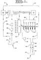
- Fuel system 10 includes one or more hydraulically actuated electronically-controlled fuel injectors 15, which are adapted to be positioned in a respective cylinder head bore of engine 12.
- Fuel system 10 includes an apparatus or means 16 for supply actuating fluid to each fuel injector 15, an apparatus or means 18 for supplying fuel to each injector, a computer 20 including an electronic control module 21 for electronically controlling the fuel injection system, and an apparatus or means 22 for re-circulating actuation fluid and for recovering hydraulic energy from the actuation fluid leaving each of the injectors.
- the actuating fluid supply means 16 preferably includes the actuation fluid re-circulating means 22, an actuating fluid sump 24, a relatively low pressure actuating fluid transfer pump 26, a re-circulation line 27 that connects actuator fluid drains of the fuel injectors 15 with the re-circulating means 22, an actuating fluid cooler 28, one or more actuation fluid filters 30, a high pressure pump 32 for generating relatively high pressure in the actuation fluid, a re-circulation line 33 that connects the re-circulating means 22 with the actuating fluid supply means 16, and at least one relatively high pressure actuation fluid manifold 36.
- a common rail passage 38 is arranged in fluid communication with the outlet from the relatively high pressure actuation fluid pump 32.
- a rail branch passage 40 connects the actuation fluid inlet of each fuel injector 15 to the high pressure common rail passage 38.
- the fuel supply means 18 preferably includes a fuel tank 42, a fuel supply passage 44 arranged in fluid communication between fuel tank 42 and the fuel inlet 60 (FIG. 2) of each fuel injector 15, a relatively low pressure fuel transfer pump 46, one or more fuel filters 48, a fuel supply regulating valve 49, and a fuel circulation and return passage 47 arranged in fluid communication between fuel injectors 15 and fuel tank 42.
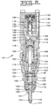
- FIGS. 5-7 illustrate an embodiment of a fuel injector 15 having an actuation fluid control valve 203 according to the invention.
- This particular embodiment is adapted for a direct-injection diesel-cycle internal combustion engine, but the invention can be used in fuel injectors 15 in other types of engines as well.
- Fuel injectors 15 having the actuation fluid control valve 203 according to the invention can be used in fuel injection systems 10 such as the one illustrated in FIG. 1 and described above. The components and portions of the fuel injector 15 of this embodiment are described below with reference to figs 5-7.
- the fuel injector 15 of this embodiment utilizes a single attractive two-way solenoid actuator 205, although other embodiments utilizing the invention can make use of piezo stack or other types of actuators 205.
- the actuator 205 includes an armature 207 attached with an actuation valve member 209 slidably disposed in an actuator bore 211 having an actuator bore wall 213.
- the actuation valve member 209 is slidable between two positions. At a first position the actuation valve member 209 mates with a drain seat 215, and at the second position the actuation valve member 209 mates with an inlet seat 217.
- An actuator spring 218 biases the armature 207 and thus the attached actuation valve member 209 toward the first position.
- the actuation valve member 209 has a substantially meniscus-shaped inlet pin surface 219 partially defining a fluid entry chamber 221 within the actuator bore 211.
- the fluid entry chamber 221 is fluidly connected with a source of high pressure actuation fluid that enters the fuel injector 15 through an actuation fluid inlet 223.
- the actuation valve member 209 also has a corn-shape drain pin surface 225 exposed to a low pressure actuator fluid drain 227.
- the actuation valve member 209 also has a central pin surface 229 that is exposed to a check control cavity 231 fluidly connected with a check control chamber 233 partially defined by a closing hydraulic surface 235 of a check valve member 237.
- the check control cavity 231 is also fluidly connected with a lower end hydraulic surface 239 of a spool valve member 241 slidably disposed in a spool valve bore 243.
- the spool valve member 241 is biased in an upward direction (relative to FIGS. 5-7) by a spool valve spring 245, and has an upper end hydraulic surface 247 on an end of the spool valve member 241 from the lower end hydraulic surface 239.
- the spool valve member 241 partially defines an intensifier control passage 249 that is fluidly connected with a stepped top 251 of an intensifier piston 253 slidably disposed in a stepped piston bore 255.
- the intensifier piston 253 is upwardly biased by a plunger spring 257 that surrounds a plunger 259.
- the plunger 259 is slidably disposed in a plunger bore 261. A portion of the plunger 259 extends upward into the stepped piston bore 255.
- a fuel pressurization chamber 263 Beneath the plunger 259 in the plunger bore 261 is a fuel pressurization chamber 263 fed by a supply of fuel that enters the fuel injector 15 through a fuel inlet 265.
- the fuel pressurization chamber 263 is fluidly connected via a connection passage 267 with a nozzle chamber 269 surrounding a lower check portion 271 of the check valve member 237.
- the nozzle chamber 269 comprises one or more nozzle outlets 273 for allowing pressurized fuel to leave the fuel injector 15.
- the check valve member 237 in this particular embodiment can be thought of as comprising generally the lower check portion 271 and an upper check portion 275.
- the lower check portion 271 is slidably disposed in a nozzle sleeve bore 279 of a nozzle sleeve 277, and extends into the nozzle chamber 269 wherein a lower check guide portion 281 of the lower check portion 271 is slidably disposed within a nozzle bore 283.
- Other embodiments of fuel injectors 15 utilizing the invention may lack a lower check guide portion.
- the upper check portion 275 of the check valve member 237 comprises the closing hydraulic surface 235 and is slidably disposed within the check control chamber 233.
- the check valve member 237 is downwardly biased by a check spring 285 that is within the check control chamber 233 in this embodiment.
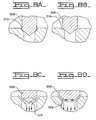
- FIGS. 8A and 8B illustrate two different types of seating configurations.
- an actuation valve member 309 seats with a drain seat 315 in an outside diameter (OD) seating configuration in which points of contact coincide with an outside diameter of the actuation valve member 309.
- the actuation valve member 309 seats with a drain seat 316 in an inside diameter (ID) seating configuration in which the points of contact coincide with an inner diameter of the actuation valve member 309.
- FIG. 8C illustrates hydraulic fluid flow past an actuation valve member 309 having a corn-shape drain pin surface 325.
- FIG. 8D illustrates hydraulic fluid flow past an actuation valve member 310 having a truncated drain pin surface 326.
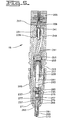
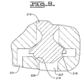
- FIG. 9 illustrates another embodiment of an actuation valve member 210 according to the invention, wherein the same element numbers are used as in FIG. 6 to label correspondingly similar elements.
- the actuation valve member 210 of this embodiment has a flattened or truncated drain pin surface 226.
- the seated pin actuator valve according to the invention performs the same function has the ball-and-pin actuator valve, but there are several important differences.
- the seated pin actuator valve is pressure balanced and therefore independent of rail pressure.
- motion of the armature and actuation valve member (pin) depends on the magnetic force and the spring force only.
- the repeatability of armature motion is insensitive to rail pressure variation from shot-to-shot, which is critical to improvement of injector stability, especially at idle condition.
- the seated pin has smaller pin lift compared to the ball-and-pin design. Effective flow areas at open and closed positions are achieved with a sizable reduction in pin lift. Since the seated pin design eliminates the pre-ball travel (the distance the armature has to move before hitting the ball in order to overcome the rail pressure against the ball), the initial air-gap between the solenoid and the armature is significantly reduced.
- the smaller pin lift reduces the pin's travel time between the upper and lower seats, and reduces the minimum dwell time for idle split injection.
- the smaller initial air-gap improves the solenoid force significantly, and the pull-in current and duration are significantly reduced.
- the fuel injectors 15 receive high pressure actuation fluid from the actuation fluid supply means 16 via the pump 32 and the common rail 36. Actuation fluid leaving the actuation fluid drain of each fuel injector 15 enters the re-circulation line 27 that carries it to the hydraulic energy re-circulating or recovering means 22. A portion of the re-circulated actuation fluid is channeled to the high pressure actuation fluid pump 32 and another portion is returned to the actuation fluid sump 24 of the actuation fluid supply means 16 via the re-circulation line 33.
- the fuel injectors 15 receive fuel from the fuel supply means 18 via the fuel supply passage 44, after the fuel has passed through the fuel transfer pump 46 and the fuel filters 48.
- the actuation fluid is engine lubricating oil and the actuation fluid sump 24 is the engine lubrication oil sump. This allows the fuel injection system 10 to be connected as a parasitic subsystem to the engine's lubricating oil circulation system.
- the actuation fluid could be fuel provided by the fuel tank 42 or another source, such as coolant fluid, etc.
- the computer 20 preferably includes an electronic control module 11 which controls the fuel injection timing; the total fuel injection quantity during an injection cycle; the fuel injection pressure; the number of separate injections or injection segments during each injection cycle; the time intervals between the injection segments; the fuel quantity of each injection segment during an injection cycle; the actuation fluid pressure; any combination of the above parameters.
- the computer 20 receives a plurality of sensor input signals S 1 -S 8 which correspond to known sensor inputs, such as engine operating condition, load, etc., that are used to determine the precise combination of injection parameters for the subsequent injection cycle.
- computer 20 issues control signal S 9 to control the actuation fluid pressure and the control signal S 10 to control the fluid actuation fluid control valve(s) 203 within each fuel injector 15.
- Each of the injection parameters are variably controllable independent of engine speed and load.
- control signal S 10 is current to the actuator 205 commanded by the computer.
- each fuel injector 15 Operation of each fuel injector 15 is now described with reference to FIGS. 5-7.
- the check control cavity 231 is in fluid communication with high pressure hydraulic fluid from the actuation fluid inlet 223, so that the high pressure actuating fluid pushes against the lower end hydraulic surface 239 of the spool valve member 241 to balance the force of the high pressure hydraulic fluid pushing down on the upper end hydraulic surface 247 of the spool valve member 241.
- the bias provided by the spool valve spring 245 keeps the spool valve member 241 positioned so that the intensifier control passage 249 is open to an actuator fluid drain 227.
- the bias provided by the plunger spring 257 keeps the intensifier piston 253 from pressurizing fuel in the fuel pressurization chamber 263. Accordingly, there is only low pressure fuel in the nozzle chamber 269. Even without the force of hydraulic fluid pushing down on the closing hydraulic surface 235 of the check valve member 237, the bias provided by the check spring 285 is sufficient to keep the check valve member 237 pushed down so that it blocks fuel from reaching the nozzle outlets 273.
- the actuator 205 is energized, pulling the armature 207 and also pulling the actuation valve member 209 to the second position.
- One desirable feature of this design is that the meniscus-shaped inlet pin surface 219 of the actuation valve member 209 largely eliminates horizontal surfaces of the actuation valve member 209 at the actuation fluid inlet 223. The lack of sharp corners in the fluid entry chamber 221 is conducive to smoother flow of the hydraulic fluid.
- minimizing the horizontal components of the inlet pin surface 215 and tapering the inlet pin surface to adjust the width and/or depth of the fluid entry chamber 221 in a vertically symmetrical manner creates a vertical symmetry of velocity of the high pressure hydraulic fluid flowing through the fluid entry chamber 221 when the actuation valve member 209 is at the first position and fluid is flowing through the fluid entry chamber 221 past the inlet seat 217.
- a vertical symmetry of fluid velocity can keep an additional net vertical force from being introduced due to variations in hydraulic fluid pressure caused by velocity of the hydraulic fluid.
- This pressure-balanced design results in much reduced shot-to-shot variation in fuel delivery and timing over previous designs because the actuation valve member 209 moving forces are essentially independent of variations in actuation fluid pressure. Additionally, much less electrical energy is required of the actuator 205, compared with designs such as that shown in FIGS. 2-4, where the actuator 205 must push against the force of high pressure actuation fluid. There is also faster check valve control response and reduction of noise over previous designs, at least in part due to the relatively small mass of the seated pin actuation valve member 209.
- the intensifier piston 253 pushes the plunger 259 down, pressurizing fuel in the fuel pressurization chamber 263.
- the pressurized fuel flows through the connection passage 267 to the nozzle chamber 269. Since there is now only low pressure against the closing hydraulic surface 235 of the check valve member 237, the force provided by the pressurized fuel in the nozzle chamber 269 is sufficient to overcome the bias provided by the check spring 285. As a result the check valve member 237 moves up, allowing highly pressurized fuel to exit the fuel injector 15, into the engine combustion chamber for example.
- the actuator 205 is de-energized, allowing the actuator spring 216 to move the actuation valve member 209 back to the first position.
- the check control cavity 231 is closed off from the actuator fluid drain 227, and is fluidly connected to the high pressure actuation fluid from the actuation fluid inlet 223. This causes high pressure actuation fluid to be applied to the lower end hydraulic surface 239 of the spool valve member 241, once again balancing the force of the high pressure actuation fluid against the upper end hydraulic surface 247 of the spool valve member 241.
- the bias provided by the spool valve spring 245 can now move the spool valve member 241 upward to cut off the supply of high pressure actuation fluid from the intensifier control passage 249 and to relieve the pressure in the intensifier control passage 249 by exposing it to the actuator fluid drain 227.
- the bias provided by the plunger spring 257 is now able to push the intensifier piston 253 upward. This reduces the pressure of the fuel in the fuel pressurization chamber 263, and hence in the nozzle chamber 269, allowing the bias provided by the check spring 285 to push the check valve member 237 toward its closed position.
- the actuator 205 can be turned rapidly on and off to directly control the check valve member 237 by acting on its closing hydraulic surface 235. Doing this can make the check valve member 237 open and close as many times as desired at any time during the injection cycle. For example, this feature can be used to cause a short delay after a "pilot" fuel injection at the beginning of an injection cycle in order to reduce engine emissions or for other reasons.
- Choice of seating configuration is a very important for performance of the injector 10 for controlling fuel growth over the lifetime of the fuel injector.
- any poppet valve there are two types of the seating configurations as explained above: OD (FIG. 8A) and ID (FIG. 8B).
- Choice of the seating configuration affects growth direction of sealing length (width of the annulus of actual contact between the pin and a seat) as wear occurs at the contact areas. For the OD seated valve the sealing length grows toward the center of the valve. For the ID seated valve the sealing length grows away from the center.
- seating configuration in the illustrated embodiments is based on consideration of the actual operating conditions of the valve and control of sealing length growth over time. It will be understood that pressure against valve components at the seats (when closed) will vary with the seating diameter, defined by the upstream contact point between the pin and a respective seat when that seat is closed.
- the inlet seat 217, 218 is ID seated and the drain seat 215, 216 is OD seated, as is most clearly illustrated in FIG. 9.
- the inlet seat 217, 218 is ID seated for two reasons; the inlet seat 217, 218 must be pressure balanced when the pin is at the second position, and growth of the seating diameter must not significantly affect movement of the pin.
- the seating diameter of the inlet seat 217, 218 is the same as the diameter of the actuator bore 211. If the inlet seat 217, 218 were OD seated, then the seating diameter would be larger than the diameter of the actuator bore 211 and the seating diameter would change with seat wear.
- the drain seat 215, 216 is OD seated so that the sealing length grows toward the center of the valve, which will not change the seating diameter at the drain seat 215, 216.
- the inlet seat 217, 218 seating diameter and the drain seat 215, 216 seating diameter should have been chosen to pressure balance the valve. If the lower seat were ID seated, the sealing length would grow away from the center, and the seating diameter would grow larger with time, disrupting the balance between the upper seat and lower seat seating diameters and requiring a higher solenoid pull-in current.
- the corn-shape drain pin surface 225 of the actuation valve member 209 results in a smooth flow of hydraulic fluid. This is illustrated in FIG. 8C for a representative actuation valve member 309 having a corn-shaped drain pin surface 325. The flow is smooth and there is no separation flow current. The pressure profile on the drain pin surface 225, 325 is linearly decreasing, and the resulting force on the actuation valve member 209, 309 is a significant part of the flow force.
- Eliminating this unbalancing flow force can be accomplished by using a truncated drain pin surface 226, which changes the flow characteristics for the actuation valve member 210. This is illustrated in FIG. 8D for a representative actuation valve member 310 having a truncated drain pin surface 326. In this configuration, the flow separates after passing the seat and forms a low-pressure separation flow zone. The pressure in this zone is close to the atmospheric pressure and it does not create significant flow force acting on the truncated drain pin surface 226, 326.
- the seated-pin actuator described herein and implemented in Caterpillar's HEUI-BTM fuel injector results in a hydraulically actuated fuel injector having better stability, full injection rate shaping capability, lower electric energy consumption, and the higher pressure capability.
- the actuation fluid control valve 203 of the invention is shown in a HEUI-BTM type fuel injector manufactured by Caterpillar Inc. and can be incorporated in other HEUITM models as well.
- the actuation fluid control valve 203 of the invention can be adapted for use in any hydraulically actuated fuel injector, or in other hydraulically actuated devices such as hydraulic engine brake actuators for example, and other hydraulic control devices of moveable.
Landscapes
- Engineering & Computer Science (AREA)
- Chemical & Material Sciences (AREA)
- Combustion & Propulsion (AREA)
- Mechanical Engineering (AREA)
- General Engineering & Computer Science (AREA)
- Physics & Mathematics (AREA)
- Electromagnetism (AREA)
- Fuel-Injection Apparatus (AREA)
Applications Claiming Priority (5)
| Application Number | Priority Date | Filing Date | Title |
|---|---|---|---|
| US11089798P | 1998-12-04 | 1998-12-04 | |
| US110897P | 1998-12-04 | ||
| US358990 | 1999-07-22 | ||
| US09/358,990 US6364282B1 (en) | 1998-12-04 | 1999-07-22 | Hydraulically actuated fuel injector with seated pin actuator |
| PCT/US1999/027545 WO2000034647A1 (en) | 1998-12-04 | 1999-11-19 | Hydraulically actuated fuel injector with seated pin actuator |
Publications (2)
| Publication Number | Publication Date |
|---|---|
| EP1053397A1 EP1053397A1 (en) | 2000-11-22 |
| EP1053397B1 true EP1053397B1 (en) | 2004-06-16 |
Family
ID=26808485
Family Applications (1)
| Application Number | Title | Priority Date | Filing Date |
|---|---|---|---|
| EP99961729A Expired - Lifetime EP1053397B1 (en) | 1998-12-04 | 1999-11-19 | Hydraulically actuated fuel injector with seated pin actuator |
Country Status (5)
| Country | Link |
|---|---|
| US (1) | US6364282B1 (enExample) |
| EP (1) | EP1053397B1 (enExample) |
| JP (1) | JP4418594B2 (enExample) |
| DE (1) | DE69918058T2 (enExample) |
| WO (1) | WO2000034647A1 (enExample) |
Cited By (1)
| Publication number | Priority date | Publication date | Assignee | Title |
|---|---|---|---|---|
| US9739230B2 (en) | 2014-02-17 | 2017-08-22 | GM Global Technology Operations LLC | Method of operating a fuel injector |
Families Citing this family (20)
| Publication number | Priority date | Publication date | Assignee | Title |
|---|---|---|---|---|
| DE19939457A1 (de) * | 1999-08-20 | 2001-03-01 | Bosch Gmbh Robert | Hydraulische Steuervorrichtung |
| DE10059424A1 (de) * | 2000-11-30 | 2002-06-06 | Bosch Gmbh Robert | Hubgesteuertes Ventil als Kraftstoff-Zumesseinrichtung eines Einspritzsystems für Brennkraftmaschinen |
| US6725838B2 (en) | 2001-10-09 | 2004-04-27 | Caterpillar Inc | Fuel injector having dual mode capabilities and engine using same |
| US7174881B2 (en) * | 2001-12-07 | 2007-02-13 | Caterpillar Inc. | Actuation valve for controlling fuel injector and compression release valve, and engine using same |
| US6978943B2 (en) * | 2002-01-30 | 2005-12-27 | International Engine Intellectual Property Company, Llc | Governor plate apparatus |
| US6857418B2 (en) * | 2002-10-15 | 2005-02-22 | International Engine Intellectual Property Company, Llc | Fuel injection timing compensation based on engine load |
| JP4019934B2 (ja) * | 2002-12-26 | 2007-12-12 | 株式会社デンソー | 制御弁および燃料噴射弁 |
| DE10335059A1 (de) * | 2003-07-31 | 2005-02-17 | Robert Bosch Gmbh | Schaltventil für einen Kraftstoffinjektor mit Druckübersetzer |
| DE10342567A1 (de) * | 2003-09-15 | 2005-04-14 | Robert Bosch Gmbh | Vorrichtung zum Einspritzen von Kraftstoff |
| DE10344897A1 (de) * | 2003-09-26 | 2005-04-21 | Bosch Gmbh Robert | Ventil zur Steuerung einer Verbindung in einem Hochdruckflüssigkeitssystem, insbesondere einer Kraftstoffeinspritzeinrichtung für eine Brennkraftmaschine |
| ITMI20031927A1 (it) * | 2003-10-07 | 2005-04-08 | Med S P A | Elettroiniettore perfezionato per combustibile gassoso. |
| DE102004002088A1 (de) * | 2004-01-15 | 2005-08-04 | Robert Bosch Gmbh | Druckgesteuerter CR-Injektor zur Kraftstoff-Einspritzung in Brennräume von Brennkraftmaschinen, insbesondere Dieselmotoren |
| DE102004024215A1 (de) * | 2004-05-15 | 2005-12-08 | L'orange Gmbh | Steuerventil |
| CN1712696B (zh) * | 2004-06-25 | 2012-07-04 | 株式会社电装 | 用于控制喷油器操作的压力控制阀 |
| DE602005017941D1 (de) * | 2005-02-08 | 2010-01-07 | Bosch Gmbh Robert | Befestigung eines ankers an einer ventilnadel in einem steuerventil für ein kraftstoffeinspritzventil |
| US20070290152A1 (en) * | 2006-06-16 | 2007-12-20 | Pengfei Ma | Poppet valve |
| DE102007035698A1 (de) * | 2007-07-30 | 2009-02-05 | Robert Bosch Gmbh | Kraftstoffeinspritzventil mit verbesserter Dichtheit am Dichtsitz eines druckausgeglichenen Steuerventils |
| US10060421B2 (en) * | 2015-06-29 | 2018-08-28 | Caterpillar Inc. | Hydraulic drive multi-element cryogenic pump |
| DK179213B9 (en) * | 2016-12-01 | 2018-04-16 | Man Diesel & Turbo Filial Af Man Diesel & Turbo Se Tyskland | A fuel valve for injecting a liquid fuel into a combustion chamber of a large compression-igniting turbocharged two-stroke internal combustion engine |
| WO2020129631A1 (ja) * | 2018-12-19 | 2020-06-25 | 日立オートモティブシステムズ株式会社 | 燃料噴射制御装置 |
Citations (1)
| Publication number | Priority date | Publication date | Assignee | Title |
|---|---|---|---|---|
| US5121730A (en) * | 1991-10-11 | 1992-06-16 | Caterpillar Inc. | Methods of conditioning fluid in an electronically-controlled unit injector for starting |
Family Cites Families (12)
| Publication number | Priority date | Publication date | Assignee | Title |
|---|---|---|---|---|
| US4603671A (en) | 1983-08-17 | 1986-08-05 | Nippon Soken, Inc. | Fuel injector for an internal combustion engine |
| JP2712760B2 (ja) | 1990-05-29 | 1998-02-16 | トヨタ自動車株式会社 | 燃料噴射弁 |
| US5438968A (en) | 1993-10-06 | 1995-08-08 | Bkm, Inc. | Two-cycle utility internal combustion engine |
| DE4341543A1 (de) | 1993-12-07 | 1995-06-08 | Bosch Gmbh Robert | Kraftstoffeinspritzeinrichtung für Brennkraftmaschinen |
| GB9411345D0 (en) | 1994-06-07 | 1994-07-27 | Lucas Ind Plc | Fuel supply system |
| US5687693A (en) | 1994-07-29 | 1997-11-18 | Caterpillar Inc. | Hydraulically-actuated fuel injector with direct control needle valve |
| US5669355A (en) | 1994-07-29 | 1997-09-23 | Caterpillar Inc. | Hydraulically-actuated fuel injector with direct control needle valve |
| JPH08158981A (ja) * | 1994-12-02 | 1996-06-18 | Nippondenso Co Ltd | 燃料噴射装置 |
| US5518030A (en) | 1994-12-12 | 1996-05-21 | Cummins Engine Company, Inc. | Three-way flow valve with variable drain orifice area |
| US5641148A (en) * | 1996-01-11 | 1997-06-24 | Sturman Industries | Solenoid operated pressure balanced valve |
| DE19709794A1 (de) * | 1997-03-10 | 1998-09-17 | Bosch Gmbh Robert | Ventil zum Steuern von Flüssigkeiten |
| US6102004A (en) * | 1997-12-19 | 2000-08-15 | Caterpillar, Inc. | Electronic control for a hydraulically activated, electronically controlled injector fuel system and method for operating same |
-
1999
- 1999-07-22 US US09/358,990 patent/US6364282B1/en not_active Expired - Lifetime
- 1999-11-19 JP JP2000587071A patent/JP4418594B2/ja not_active Expired - Fee Related
- 1999-11-19 DE DE69918058T patent/DE69918058T2/de not_active Expired - Lifetime
- 1999-11-19 EP EP99961729A patent/EP1053397B1/en not_active Expired - Lifetime
- 1999-11-19 WO PCT/US1999/027545 patent/WO2000034647A1/en not_active Ceased
Patent Citations (1)
| Publication number | Priority date | Publication date | Assignee | Title |
|---|---|---|---|---|
| US5121730A (en) * | 1991-10-11 | 1992-06-16 | Caterpillar Inc. | Methods of conditioning fluid in an electronically-controlled unit injector for starting |
Cited By (1)
| Publication number | Priority date | Publication date | Assignee | Title |
|---|---|---|---|---|
| US9739230B2 (en) | 2014-02-17 | 2017-08-22 | GM Global Technology Operations LLC | Method of operating a fuel injector |
Also Published As
| Publication number | Publication date |
|---|---|
| JP2002531769A (ja) | 2002-09-24 |
| WO2000034647A1 (en) | 2000-06-15 |
| US6364282B1 (en) | 2002-04-02 |
| EP1053397A1 (en) | 2000-11-22 |
| DE69918058D1 (de) | 2004-07-22 |
| JP4418594B2 (ja) | 2010-02-17 |
| DE69918058T2 (de) | 2005-07-07 |
Similar Documents
| Publication | Publication Date | Title |
|---|---|---|
| EP1053397B1 (en) | Hydraulically actuated fuel injector with seated pin actuator | |
| US5890471A (en) | Fuel injection device for engines | |
| US6065450A (en) | Hydraulically-actuated fuel injector with direct control needle valve | |
| US5697342A (en) | Hydraulically-actuated fuel injector with direct control needle valve | |
| US5472142A (en) | Accumulator fuel injection apparatus | |
| US5878720A (en) | Hydraulically actuated fuel injector with proportional control | |
| EP0829640A2 (en) | Hydraulically-actuated fuel injector with direct control needle valve | |
| US6082332A (en) | Hydraulically-actuated fuel injector with direct control needle valve | |
| EP1080306B1 (en) | Hydraulically-actuated fuel injector with rate shaping spool control valve | |
| EP1163440B1 (en) | Fuel injector | |
| US5655501A (en) | Rate shaping plunger/piston assembly for a hydraulically actuated fuel injector | |
| US20030178508A1 (en) | Two stage intensifier | |
| US6935580B2 (en) | Valve assembly having multiple rate shaping capabilities and fuel injector using same | |
| US6568369B1 (en) | Common rail injector with separately controlled pilot and main injection | |
| US6129072A (en) | Hydraulically actuated device having a ball valve member | |
| EP0582993B1 (en) | Accumulator fuel injection apparatus | |
| WO2005066485A1 (en) | Fuel injector with piezoelectric actuator and method of use | |
| US20090114744A1 (en) | Device for the Injection of Fuel Into the Combustion Chamber of an Internal Combustion Engine | |
| JPH10110658A (ja) | 直接制御型ニードルバルブを有する油圧作動燃料噴射器 | |
| JPH10131828A (ja) | 噴射弁装置 | |
| KR20020084235A (ko) | 3/2 방향 제어 밸브 | |
| US20030080216A1 (en) | Fuel injection system for internal combustion engines | |
| KR100241037B1 (ko) | 디젤기관용 전자제어식 고압연료분사기 | |
| JPH0429082Y2 (enExample) | ||
| EP1287256B1 (en) | A fuel injector |
Legal Events
| Date | Code | Title | Description |
|---|---|---|---|
| PUAI | Public reference made under article 153(3) epc to a published international application that has entered the european phase |
Free format text: ORIGINAL CODE: 0009012 |
|
| AK | Designated contracting states |
Kind code of ref document: A1 Designated state(s): AT BE CH CY DE DK ES FI FR GB GR IE IT LI LU MC NL PT SE |
|
| 17P | Request for examination filed |
Effective date: 20001205 |
|
| 17Q | First examination report despatched |
Effective date: 20030221 |
|
| GRAP | Despatch of communication of intention to grant a patent |
Free format text: ORIGINAL CODE: EPIDOSNIGR1 |
|
| GRAS | Grant fee paid |
Free format text: ORIGINAL CODE: EPIDOSNIGR3 |
|
| GRAA | (expected) grant |
Free format text: ORIGINAL CODE: 0009210 |
|
| AK | Designated contracting states |
Kind code of ref document: B1 Designated state(s): DE FR GB |
|
| PG25 | Lapsed in a contracting state [announced via postgrant information from national office to epo] |
Ref country code: FR Free format text: LAPSE BECAUSE OF NON-PAYMENT OF DUE FEES Effective date: 20040616 |
|
| REG | Reference to a national code |
Ref country code: GB Ref legal event code: FG4D |
|
| REF | Corresponds to: |
Ref document number: 69918058 Country of ref document: DE Date of ref document: 20040722 Kind code of ref document: P |
|
| REG | Reference to a national code |
Ref country code: IE Ref legal event code: FG4D |
|
| PG25 | Lapsed in a contracting state [announced via postgrant information from national office to epo] |
Ref country code: GB Free format text: LAPSE BECAUSE OF NON-PAYMENT OF DUE FEES Effective date: 20041119 |
|
| PLBE | No opposition filed within time limit |
Free format text: ORIGINAL CODE: 0009261 |
|
| STAA | Information on the status of an ep patent application or granted ep patent |
Free format text: STATUS: NO OPPOSITION FILED WITHIN TIME LIMIT |
|
| 26N | No opposition filed |
Effective date: 20050317 |
|
| EN | Fr: translation not filed | ||
| GBPC | Gb: european patent ceased through non-payment of renewal fee |
Effective date: 20041119 |
|
| PGFP | Annual fee paid to national office [announced via postgrant information from national office to epo] |
Ref country code: DE Payment date: 20121130 Year of fee payment: 14 |
|
| PG25 | Lapsed in a contracting state [announced via postgrant information from national office to epo] |
Ref country code: DE Free format text: LAPSE BECAUSE OF NON-PAYMENT OF DUE FEES Effective date: 20140603 |
|
| REG | Reference to a national code |
Ref country code: DE Ref legal event code: R119 Ref document number: 69918058 Country of ref document: DE Effective date: 20140603 |