EP1052945B1 - Instrument medical a tige tubulaire - Google Patents
Instrument medical a tige tubulaire Download PDFInfo
- Publication number
- EP1052945B1 EP1052945B1 EP99973250A EP99973250A EP1052945B1 EP 1052945 B1 EP1052945 B1 EP 1052945B1 EP 99973250 A EP99973250 A EP 99973250A EP 99973250 A EP99973250 A EP 99973250A EP 1052945 B1 EP1052945 B1 EP 1052945B1
- Authority
- EP
- European Patent Office
- Prior art keywords
- transmission element
- tubular shaft
- tubular
- shaft
- force transmission
- Prior art date
- Legal status (The legal status is an assumption and is not a legal conclusion. Google has not performed a legal analysis and makes no representation as to the accuracy of the status listed.)
- Expired - Lifetime
Links
Images

Classifications
-
- A—HUMAN NECESSITIES
- A61—MEDICAL OR VETERINARY SCIENCE; HYGIENE
- A61B—DIAGNOSIS; SURGERY; IDENTIFICATION
- A61B17/00—Surgical instruments, devices or methods, e.g. tourniquets
- A61B17/28—Surgical forceps
- A61B17/29—Forceps for use in minimally invasive surgery
- A61B17/295—Forceps for use in minimally invasive surgery combined with cutting implements
-
- A—HUMAN NECESSITIES
- A61—MEDICAL OR VETERINARY SCIENCE; HYGIENE
- A61B—DIAGNOSIS; SURGERY; IDENTIFICATION
- A61B17/00—Surgical instruments, devices or methods, e.g. tourniquets
- A61B17/28—Surgical forceps
- A61B17/29—Forceps for use in minimally invasive surgery
- A61B2017/2901—Details of shaft
- A61B2017/2902—Details of shaft characterized by features of the actuating rod
-
- A—HUMAN NECESSITIES
- A61—MEDICAL OR VETERINARY SCIENCE; HYGIENE
- A61B—DIAGNOSIS; SURGERY; IDENTIFICATION
- A61B17/00—Surgical instruments, devices or methods, e.g. tourniquets
- A61B17/28—Surgical forceps
- A61B17/29—Forceps for use in minimally invasive surgery
- A61B2017/2901—Details of shaft
- A61B2017/2904—Details of shaft curved, but rigid
-
- A—HUMAN NECESSITIES
- A61—MEDICAL OR VETERINARY SCIENCE; HYGIENE
- A61B—DIAGNOSIS; SURGERY; IDENTIFICATION
- A61B90/00—Instruments, implements or accessories specially adapted for surgery or diagnosis and not covered by any of the groups A61B1/00 - A61B50/00, e.g. for luxation treatment or for protecting wound edges
- A61B90/08—Accessories or related features not otherwise provided for
- A61B2090/0813—Accessories designed for easy sterilising, i.e. re-usable
-
- A—HUMAN NECESSITIES
- A61—MEDICAL OR VETERINARY SCIENCE; HYGIENE
- A61B—DIAGNOSIS; SURGERY; IDENTIFICATION
- A61B2217/00—General characteristics of surgical instruments
- A61B2217/002—Auxiliary appliance
- A61B2217/005—Auxiliary appliance with suction drainage system
-
- A—HUMAN NECESSITIES
- A61—MEDICAL OR VETERINARY SCIENCE; HYGIENE
- A61B—DIAGNOSIS; SURGERY; IDENTIFICATION
- A61B2217/00—General characteristics of surgical instruments
- A61B2217/002—Auxiliary appliance
- A61B2217/007—Auxiliary appliance with irrigation system
-
- A—HUMAN NECESSITIES
- A61—MEDICAL OR VETERINARY SCIENCE; HYGIENE
- A61B—DIAGNOSIS; SURGERY; IDENTIFICATION
- A61B90/00—Instruments, implements or accessories specially adapted for surgery or diagnosis and not covered by any of the groups A61B1/00 - A61B50/00, e.g. for luxation treatment or for protecting wound edges
- A61B90/70—Cleaning devices specially adapted for surgical instruments
Definitions
- the invention relates to a medical tubular shaft instrument, with an elongate tubular shaft, with at least one movable tool at the distal end, further comprising at least one movable handle portion at the proximal end, and finally with an elongate force transmission element, the distal end with the at least one tool and its proximal end is frictionally connected to the at least one movable grip part, wherein the force transmission element extends through the tubular shaft.
- tubular instruments are used in minimally invasive surgery as surgical instruments to perform surgical procedures through a small incision under endoscopic control.
- such tubular shaft instruments are provided with different functions.
- the at least one movable tool can be embodied, for example, in the form of a movable jaw part which has a cutting edge which interacts with a cutting edge of a second movable or immovable jaw part in a cutting manner.
- the at least one movable tool may also be a jaw member having a blunt surface which cooperates with a second jaw member for grasping tissue.
- the at least one movable tool has a configuration which makes it possible to hold a needle in the operating area with this tool and to guide the formation of a seam for joining tissue.
- At least one movable grip part is provided at the proximal end of the tubular shaft instrument, which is non-positively connected to the at least one movable tool via an elongate force transmission element, for example in the form of a pull rod. Movement of the movable handle portion then causes movement of the at least one movable tool at the distal end of the tubular shaft to perform the corresponding function, For example, cutting or holding and guiding the needle through the tissue to effect.
- tubular shaft instruments In the context of minimally invasive surgery, it may sometimes be necessary to design such tubular shaft instruments with a tubular shaft diameter that is about 3 mm or less. Such small tubular shaft diameters are particularly required in the operation on infants or even in operations in certain operating areas, such as in the head area.
- the force transmission element is adapted in diameter to the inner diameter of the tubular shaft, i. the outer diameter of the force transmission element is about as large as the inner diameter of the tubular shaft, so that the force transmission element completely fills the interior of the tubular shaft.
- the disadvantage of this embodiment is that the interior of the tubular shaft can not be sufficiently flush with built-in power transmission element, as between the power transmission element and the tubular shaft no sufficient passage for a rinsing liquid is present.
- miniaturized tubular shaft instruments are not disassembled in the way, at least not so easily dismantled that the power transmission element for cleaning out of the tubular shaft can be removed, because the connection between the at least one movable tool and the power transmission element on the one hand and the power transmission element and the at least one movable handle part on the other hand is not or not easily solved, this means that the known tubular shaft instruments only insufficiently cleanable. Therefore, accumulating during an operation in the interior of the tubular shaft contaminants can not be removed so far that this Rohrschaftinstrumente can meet the strict sterility and hygiene requirements.
- a surgical instrument is known from the German utility model DE-4-7330291, in which spacer balls or rollers are placed on the shaft at certain intervals in order to make it stand in the carbon shaft.
- the invention is therefore the object of developing a tubular shaft instrument of the type mentioned in that the tubular shaft instrument by flushing the interior of the tubular shaft with built-in power transmission element is easy to clean, and that the stability of the tubular shaft instrument is still guaranteed against bending of the tubular shaft.
- this object is achieved with respect to the above-mentioned Rohrschaftinstrumentes that the force transmission element at least in its extending through the tubular shaft region at least partially extends radially at least three circumferential points to an inner wall of the tubular shaft and has a clearance between the three circumferential locations of the inner wall , And in its remaining, extending through the tubular shaft sections at least partially having a clear distance from the inner wall.
- the force transmission element at least partially in its extending through the tubular shaft region has a clear distance from the inner wall of the tubular shaft, so that the interior of the tubular shaft has a purge area sufficient for cleaning even with a built-in force transmission element.
- the invention provides that the force transmission element axially at least partially extends at least three circumferential locations radially up to the inner wall of the tubular shaft.
- the power transmission element also has the task to stabilize the tubular shaft against bending during the transmission of high tensile forces.
- the design of the force transmission element characterized in that this extends at least partially radially at three circumferential points to the inner wall of the tubular shaft and thereby stabilizes the tubular shaft.
- the power transmission element in these sections between the circumferential locations to the inner wall of the tubular shaft on a clearance for the passage of a rinsing liquid.
- the force transmission element according to the present invention in the axial sections, where the force transmission element extends to the inner wall of the tubular shaft be formed in cross-section approximately triangular.
- the tubular shaft instrument according to the invention is easy to clean due to the continuous between the force transmission element and the tubular shaft through flushing channel, and despite the existing continuous Spülraumes occurs no loss of stability of the tubular shaft.
- the at least three extend radially up to the inner wall of the tubular shaft Circumferential points continuously over the entire, extending through the tubular shaft portion of the power transmission element.
- the at least three circumferential points extend not only in sections over the force transmission element, but over the entire extending in the tubular shaft region of the force transmission element.
- the advantage is achieved that the tubular shaft undergoes stabilization through the force transmission element over its entire length.
- the manufacture of the power transmission element is simplified.
- the force transmission element may be formed of a cylindrical solid material by introducing at least three continuous flats or depressions in the axial direction in a material-removing process, for example by laser techniques or spark erosion, or in a non-abrasive process, for example by rolling or profiling, i. Shapes are made by pulling a round material through a corresponding die.
- the force transmission element is rounded at the at least three circumferential locations.
- the radius of curvature of the circumferential points is smaller than the inner radius of the tubular shaft.
- the force transmission element rests with its at least three circumferential points only linearly on the inner wall of the tubular shaft, whereby the friction is minimized in the axial reciprocating movement of the power transmission element in the tubular shaft during use of the tubular shaft instrument.
- the existing for the passage of a rinsing liquid flushing cross section between the power transmission element and the tubular shaft is increased, and it will be minimized for the rinse liquid hard to reach areas between the outer contour of the force transmission element and the inner wall of the tubular shaft.
- the force transmission element between the at least three circumferential locations is recessed concave toward the longitudinal center axis of the power transmission element.
- the at least three circumferential points extending radially as far as the inner wall of the tubular shaft extend in a straight line.
- the force transmission element can be produced easily, although it can also be considered that the at least three circumferential points extend helically around the longitudinal central axis of the force transmission element.
- the at least three circumferential locations occupy an equal angular distance from one another.
- This configuration achieves optimum all-round and symmetrical support of the force transmission element on the inner wall of the tubular shaft.
- the inventive design of the tubular shaft instrument can be used in a pair of pliers for cutting and / or grasping as well as a needle holder.
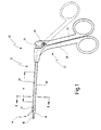
- Fig. 1 is provided with the general reference numeral 10 provided medical tubular shaft instrument.
- the medical tubing instrument 10 is, according to the embodiment shown, a medical forceps 12 for cutting tissue in the human or animal body.
- the forceps 12 has at least one movable tool 14 at the distal end.
- the tool 14 is a movable jaw member 16 which cooperates with another jaw member 18, which in this case is immobile but may also be movable.
- the two jaws 16 and 18 are attached to the distal end of a tubular shaft 20.
- the tubular shaft 20 is designed as a hollow cylinder.
- the tubular shaft 20 has in the present Furthermore, case has an outer diameter of about 3 mm or less.
- the tubular shaft 20 is still rigid.
- the handle 22 has at least one movable handle portion 24 which facilitates actuation of the at least one movable tool 14, i. here of a jaw 16, serves.
- the movable handle part 24 is connected via a hinge 26 hingedly connected to a stationary, with the tubular shaft 20 firmly connected handle portion 28.
- a force transmission element 30 is provided, which is indicated in Fig. 1 by broken lines and in Fig. 2 and 4 shown in more detail.
- the power transmission element 30 is interposed between the at least one movable tool 14, i. here the movable jaw part 16 and the at least one movable grip part 24 connected. More specifically, a distal end 32 of the power transmission member 30 is connected to the movable jaw member 16 and a proximal end 34 of the power transmission member 30 is connected to the movable handle member 24.
- the power transmission element 30 extends through the tubular shaft 20, i. is disposed in the tubular shaft 20.
- the power transmission element 30 operates to close the jaw members 16 and 18 to train, ie from the open position of the movable jaw member shown in Fig. 1 with broken lines 16, which corresponds to the broken line position of the movable handle portion 24, is pulled proximally by moving the movable handle portion 24 onto the stationary handle portion 28 toward the force transmitting member 30 in the tubular shaft 20, thereby closing the movable jaw portion 16 against the stationary jaw portion 18 becomes.
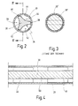
- the force transmission element 30 at least in its extending through the tubular shaft 20 region an outer contour 36 which axially at least partially at least three circumferential locations , which are designated in Fig. 2 with 38, 40 and 42, extends radially to an inner wall 44 of the tubular shaft 20 and thereby ensures an all-round support of the tubular shaft 20.
- the at least three peripheral locations 38, 40 and 42 are provided on two axial sections 46 and 48 of the force transmission element 30.
- Fig. 4 illustrates only an axial section of the tubular shaft 20 and the power transmission element 30, it is understood that such portions are provided in greater numbers at least in the extending through the tubular shaft 20 portion of the force transmission element 30.
- the circumferential points 38, 40 and 42 extending radially to the inner wall 44 of the tubular shaft 20 extend over an axial partial length of the power transmission element 30.
- the force transmission element 30 no to the inner wall 44 of the tubular shaft 20 reaching and supporting at this circumferential points, the force transmission element 30 at least partially a clear distance from the inner wall 44, as shown in Fig. 4 with a portion 50 is exemplified, in which the force transmission element 30 on all sides a clearance from the inner wall 44 of the tubular shaft 20 has.
- the power transmission element 30 has a substantially triangular cross-section in the sections 46 and 48 and the other portions corresponding to these sections
- the power transmission element 30 in the section 50 and the other portions corresponding to this section 50 may have a substantially circular cross-section, wherein the round Cross-section in the portion 50 and the other portions corresponding to this section 50 has a smaller diameter than the inner wall 44 of the tubular shaft 20th
- the circumferential locations 38, 40 and 42 supported on the inner wall 44 of the tubular shaft 20 extend continuously over the entire length extending through the tubular shaft 20 Range of the force transmission element 30 humiliatrekken. This is shown in Fig. 4 with broken lines. In other words, then the power transmission element 30 at any axial position has a cross-section, as shown in Fig. 2.
- the formed in the form of webs circumferential locations 38, 40, 42 extend between the proximal end 34 and the distal end 32 in a straight line. However, it can also be provided a coiled configuration.
- each a clear space 52, 54, 56 is provided, which serves as a purge passage for the passage of a rinsing liquid.
- the usable as flushing channels spaces 52, 54, 56 thus extend over the entire length of the arranged in the tubular shaft 20 portion of the power transmission element 30th
- the force transmission element 30 is rounded.
- the radius of curvature of the peripheral locations 38, 40, 42 is smaller than the inner radius of the tubular shaft 20.
- circumferential locations 38, 40 and 42 are each at an angular distance of about 120 °, i. they take an equal angular distance from each other, whereby a uniform all-round support of the power transmission element 30 is achieved on the inner wall 44 of the tubular shaft 20.
- the power transmission element 30 is made entirely solid from a solid material, for example. From a cylindrical body, in which in the outer contour according to the embodiment in Fig. 2nd By material-removing shaping, for example. By a laser process or a spark erosion process, recesses are partially introduced. Alternatively, the power transmission element 30 with the illustrated shape in a non-material-removing process by rolling or by profile drawing, ie forms by pulling a round material by a corresponding die, are produced, the latter is preferably applied.
- FIG. 3 illustrates an embodiment of a force transmission element 30 'known from the prior art, which is arranged in a tubular shaft 20'.
- This conventional power transmission element 30 ' is like the interior of the tubular shaft 20' formed in cross section round, wherein the diameter of the force transmission element 30 'is substantially equal to the inner diameter of the tubular shaft 20'. Accordingly, no space for the passage of a rinsing liquid is present between the force transmission element 30 'and the tubular shaft 20', ie, the interior of the tubular shaft 20 'can not be rinsed. If the force transmission element 30 'were flattened on both sides to form a band on two opposite circumferential sides except for the broken lines shown in FIG.
- a sufficient flushing cross section between the force transmission element 30 and the tubular shaft 20 is provided by the illustrated in Fig. 2 inventive embodiment of the force transmission element 30, on the other hand prevent the radially reaching to the inner wall 44 of the tubular shaft 20 circumferential locations 38, 40 and 42, that the Power transmission element 30 jumps back and forth at the alternating tensile and compressive stresses and thus cause a stabilization of the tubular shaft 20, so that it does not bend even at high power loads.
- a medical Rohrschaftinstrument 60 is shown in the form of a needle holder 62, in which the invention is also applied advantageously.
- a needle is held for connecting tissue by means of a seam and passed through the tissue.
- the needle holder 62 at its distal end on two movable tools 64 and 66 in the form of two pincer-like jaw parts with which a needle, not shown, can be held and guided safely and firmly.
- the two movable tools 64 and 66 are arranged at the distal end of a tubular shaft 68, at the proximal end of which in turn a handle 70 is arranged, which in this case has two movable grip parts 72 and 74.
- the movable tools 64 and 66 are frictionally engaged with the via a power transmission member 76 extending through the tubular shaft 68 and a linkage connected to the power transmission member 76, which is composed of an axial rod 78, and two pivot levers 80 and 82 movable handle parts 72 and 74 connected.
- Axial rod 78 is biased to its maximum distal position by a leaf spring 83 engaging proximate pivot levers 80 and 82 to grip members 72 and 74.
- a compression spring 84 serves as overload protection, which is effective when an excessive force is exerted on the handle parts 72 and 74.
- the axial rod 78 By compressing the handle portions 72 and 74, the axial rod 78 is displaced proximally against the action of the leaf spring 83, whereby also the power transmission element 76 connected to the axial rod 78 is displaced proximally to close the tools 64 and 66.
- the force transmission element 76 now has, according to the invention, at least in its region extending through the tubular shaft 68, a configuration as is provided in FIG. 2 for the exemplary embodiment of the tubular shaft instrument 10 described above.
- a rinsing liquid for rinsing the interior of the tubular shaft 68 can pass between the force transmission element 76 and the tubular shaft 68.
- the stability of the tubular shaft 68 is not affected thereby, i. this is protected against bending, as already explained in the previous embodiment.
Abstract
Claims (9)
- Instrument médical à tige tubulaire, comportant une tige tubulaire (20 ; 68) allongée, au moins un outil mobile (16; 64, 66) sur l'extrémité distale, en outre au moins un élément de préhension (24 ; 72, 74) mobile sur l'extrémité proximale, et enfin un élément de transmission de force (30 ; 76) allongé, dont l'extrémité distale (32) est assemblée par coopération de force avec ledit au moins un outil (16 ; 64, 66) et dont l'extrémité proximale (34) est assemblée par coopération de force avec ledit au moins un élément de préhension (24 ; 72, 74) mobile, l'élément de transmission de force (30 ; 76) s'étendant à travers la tige tubulaire (20 ; 68), caractérisé en ce que l'élément de transmission de force (30 ; 76), au moins dans sa partie passant à travers la tige tubulaire (20 ; 68), s'étend dans le sens radial au moins par zones avec au moins trois emplacements périphériques (38, 40, 42), jusqu'à une paroi intérieure (44) de la tige tubulaire (20 ; 68) et, entre les trois emplacements périphériques (38, 40, 42), est situé à distance de la paroi intérieure (44) et, dans ses autres parties qui passent à travers la tige tubulaire (20 ; 68), est situé au moins sur une partie du pourtour à distance de la paroi intérieure (44).
- Instrument à tige tubulaire selon la revendication 1, caractérisé en ce que lesdits au moins trois emplacements périphériques (38, 40, 42), qui s'étendent dans le sens radial jusqu'à la paroi intérieure (44) de la tige tubulaire (20 ; 68), s'étendent en continu sur toute la partie de l'élément de transmission de force (30 ; 76) qui passe à travers la tige tubulaire (20 ; 68).
- Instrument à tige tubulaire selon la revendication 1 ou 2, caractérisé en ce que l'élément de transmission de force (30 ; 76) est arrondi sur lesdits au moins trois emplacements périphériques (38, 40, 42).
- Instrument à tige tubulaire selon la revendication 3, caractérisé en ce que le rayon de courbure des emplacements périphériques (38, 40, 42) est inférieur au rayon intérieur de la tige tubulaire (20 ; 68).
- Instrument à tige tubulaire selon l'une quelconque des revendications 1 à 4, caractérisé en ce que l'élément de transmission de force (30 ; 76), entre lesdits au moins trois emplacements périphériques (38, 40, 42), est creusé selon une forme concave par référence à l'axe médian longitudinal de l'élément de transmission de force (30 ; 76).
- Instrument à tige tubulaire selon l'une quelconque des revendications 1 à 5, caractérisé en ce que lesdits au moins trois emplacements périphériques (38, 40, 42), qui s'étendent dans le sens radial jusqu'à la paroi intérieure (44) de la tige tubulaire (20 ; 68), sont droits.
- Instrument à tige tubulaire selon l'une quelconque des revendications 1 à 6, caractérisé en ce que lesdits au moins trois emplacements périphériques (38, 40, 42) incluent entre eux une même distance angulaire.
- Instrument à tige tubulaire selon l'une quelconque des revendications 1 à 7, caractérisé en ce qu'il s'agit d'une pince (12) pour couper et/ou saisir.
- Instrument à tige tubulaire selon l'une quelconque des revendications 1 à 7, caractérisé en ce qu'il s'agit d'un porte-aiguille (62).
Applications Claiming Priority (3)
| Application Number | Priority Date | Filing Date | Title |
|---|---|---|---|
| DE19855968 | 1998-12-04 | ||
| DE19855968A DE19855968C1 (de) | 1998-12-04 | 1998-12-04 | Medizinisches Rohrschaftinstrument |
| PCT/EP1999/008399 WO2000033749A1 (fr) | 1998-12-04 | 1999-11-03 | Instrument medical a tige tubulaire |
Publications (2)
| Publication Number | Publication Date |
|---|---|
| EP1052945A1 EP1052945A1 (fr) | 2000-11-22 |
| EP1052945B1 true EP1052945B1 (fr) | 2006-08-02 |
Family
ID=7889960
Family Applications (1)
| Application Number | Title | Priority Date | Filing Date |
|---|---|---|---|
| EP99973250A Expired - Lifetime EP1052945B1 (fr) | 1998-12-04 | 1999-11-03 | Instrument medical a tige tubulaire |
Country Status (4)
| Country | Link |
|---|---|
| US (1) | US6419688B1 (fr) |
| EP (1) | EP1052945B1 (fr) |
| DE (2) | DE19855968C1 (fr) |
| WO (1) | WO2000033749A1 (fr) |
Families Citing this family (22)
| Publication number | Priority date | Publication date | Assignee | Title |
|---|---|---|---|---|
| US6908476B2 (en) * | 2001-12-21 | 2005-06-21 | Alcon Grieshaber Ag | Micro surgical cutting instrument configured as scissors |
| CN1323647C (zh) * | 2005-08-30 | 2007-07-04 | 徐天松 | 一种五拆卸手术钳 |
| US8377044B2 (en) | 2007-03-30 | 2013-02-19 | Ethicon Endo-Surgery, Inc. | Detachable end effectors |
| JP5160144B2 (ja) * | 2007-05-18 | 2013-03-13 | オリンパス株式会社 | 体腔内挿入具固定器具 |
| US9186203B2 (en) * | 2009-10-09 | 2015-11-17 | Ethicon Endo-Surgery, Inc. | Method for exchanging end effectors In Vivo |
| US9295485B2 (en) | 2009-10-09 | 2016-03-29 | Ethicon Endo-Surgery, Inc. | Loader for exchanging end effectors in vivo |
| US20110087265A1 (en) * | 2009-10-09 | 2011-04-14 | Nobis Rudolph H | Laparoscopic instrument with attachable end effector |
| DE102011075785A1 (de) | 2011-05-13 | 2012-11-15 | Karl Storz Gmbh & Co. Kg | Medizinisches Rohrschaftinstrument und Verfahren zur Herstellung eines Kraftübertragungselements desselben |
| US9125681B2 (en) | 2012-09-26 | 2015-09-08 | Ethicon Endo-Surgery, Inc. | Detachable end effector and loader |
| US9427227B2 (en) | 2012-12-13 | 2016-08-30 | Ethicon Endo-Surgery, Llc | Suturing device with reusable shaft and disposable cartridge |
| US9451937B2 (en) | 2013-02-27 | 2016-09-27 | Ethicon Endo-Surgery, Llc | Percutaneous instrument with collet locking mechanisms |
| USD775332S1 (en) | 2014-12-18 | 2016-12-27 | Karl Storz Gmbh & Co. Kg | Needle holder |
| US10342520B2 (en) | 2015-08-26 | 2019-07-09 | Ethicon Llc | Articulating surgical devices and loaders having stabilizing features |
| US10335196B2 (en) | 2015-08-31 | 2019-07-02 | Ethicon Llc | Surgical instrument having a stop guard |
| US10251636B2 (en) | 2015-09-24 | 2019-04-09 | Ethicon Llc | Devices and methods for cleaning a surgical device |
| US10702257B2 (en) | 2015-09-29 | 2020-07-07 | Ethicon Llc | Positioning device for use with surgical instruments |
| US10912543B2 (en) | 2015-11-03 | 2021-02-09 | Ethicon Llc | Surgical end effector loading device and trocar integration |
| US10675009B2 (en) | 2015-11-03 | 2020-06-09 | Ethicon Llc | Multi-head repository for use with a surgical device |
| US10265130B2 (en) | 2015-12-11 | 2019-04-23 | Ethicon Llc | Systems, devices, and methods for coupling end effectors to surgical devices and loading devices |
| US20170239696A1 (en) * | 2016-02-19 | 2017-08-24 | Arthrex, Inc. | Medical Instrument with Instrument Flushing System |
| US11660162B2 (en) * | 2017-12-15 | 2023-05-30 | Mark 2 Medical, Llc | Arthroscopic shaver and cleaning device and method of cleaning an arthroscopic shaver |
| EP3880094A1 (fr) * | 2018-11-15 | 2021-09-22 | Applied Medical Resources Corporation | Dispositif de préhension laparoscopique à mécanisme de préhension à limitation de force |
Family Cites Families (11)
| Publication number | Priority date | Publication date | Assignee | Title |
|---|---|---|---|---|
| US3835858A (en) * | 1972-09-05 | 1974-09-17 | Weck & Co Inc Edward | Surgical air drill |
| DE7330291U (de) * | 1973-08-20 | 1973-12-06 | Storz K | Operationsinstrumente, insbesondere zange fuer die probeexcision, fremdkoerperentfernung und dgl |
| US4649919A (en) | 1985-01-23 | 1987-03-17 | Precision Surgical Instruments, Inc. | Surgical instrument |
| DE3736150A1 (de) | 1987-10-26 | 1989-05-03 | Wolf Gmbh Richard | Zange, insbesondere hakenstanze |
| DE3800331A1 (de) * | 1988-01-08 | 1989-07-27 | Fehling Medizintechnik Gmbh | Mikrochirurgische zange, insb. fuer die biopsie |
| JPH0347246A (ja) * | 1989-04-13 | 1991-02-28 | Olympus Optical Co Ltd | 内視鏡用処置具 |
| US5007917A (en) | 1990-03-08 | 1991-04-16 | Stryker Corporation | Single blade cutter for arthroscopic surgery |
| US5344428A (en) * | 1993-03-05 | 1994-09-06 | Auburn International, Inc. | Miniature surgical instrument |
| DE4421584C2 (de) * | 1994-06-21 | 1996-05-23 | Aesculap Ag | Chirurgisches Rohrschaftinstrument |
| DE19520717C2 (de) * | 1995-06-12 | 1998-09-24 | Aesculap Ag & Co Kg | Chirurgisches Rohrschaftinstrument |
| US5810859A (en) * | 1997-02-28 | 1998-09-22 | Ethicon Endo-Surgery, Inc. | Apparatus for applying torque to an ultrasonic transmission component |
-
1998
- 1998-12-04 DE DE19855968A patent/DE19855968C1/de not_active Expired - Fee Related
-
1999
- 1999-11-03 WO PCT/EP1999/008399 patent/WO2000033749A1/fr active IP Right Grant
- 1999-11-03 EP EP99973250A patent/EP1052945B1/fr not_active Expired - Lifetime
- 1999-11-03 DE DE59913735T patent/DE59913735D1/de not_active Expired - Lifetime
-
2000
- 2000-08-02 US US09/631,194 patent/US6419688B1/en not_active Expired - Lifetime
Also Published As
| Publication number | Publication date |
|---|---|
| US6419688B1 (en) | 2002-07-16 |
| DE59913735D1 (de) | 2006-09-14 |
| EP1052945A1 (fr) | 2000-11-22 |
| WO2000033749A1 (fr) | 2000-06-15 |
| DE19855968C1 (de) | 2000-10-05 |
Similar Documents
| Publication | Publication Date | Title |
|---|---|---|
| EP1052945B1 (fr) | Instrument medical a tige tubulaire | |
| EP1055397B1 (fr) | Instrument médical de préparation de tissus | |
| DE2735706C3 (de) | Vorrichtung zum Handhaben eines medizinischen Instrumentes | |
| EP2103264B1 (fr) | Instrument médical | |
| DE10031773A1 (de) | Chirurgisches Instrument,insbesondere Pinzette oder Zange | |
| EP2316351A2 (fr) | Instrument médical destiné à installer des pinces pour tissu | |
| DE19520717C2 (de) | Chirurgisches Rohrschaftinstrument | |
| DE202009014310U1 (de) | Chirurgisches Instrument | |
| EP2769682A1 (fr) | Instrument endoscopique et tige pour un instrument endoscopique | |
| EP3876819B1 (fr) | Instrument endoscopique | |
| EP2361040B1 (fr) | Instrument pour chirurgie laparoscopique | |
| DE3620385C1 (en) | Forceps for the percutaneous removal of renal calculi | |
| DE4100422A1 (de) | Chirurgisches instrument zum trennen und koagulieren | |
| DE19837403A1 (de) | Betätigungseinheit für ein endoskopisches Behandlungsinstrument | |
| WO2018229219A1 (fr) | Transporteur d'un résectoscope et instrument d'électrode | |
| EP0916309B1 (fr) | Instrument chirurgical pour la chirurgie à caractère invasif minimum sans gaz | |
| DE10354830A1 (de) | Hochfrequenz-Schneidevorrichtung | |
| DE102018112346A1 (de) | Medizinisches Instrument | |
| DE102007030874B4 (de) | Chirurgisches Instrument | |
| DE10145107B4 (de) | Füllstab für Endoskope | |
| EP1199989B1 (fr) | Instrument medical pour creer une cavite afin de pratiquer une intervention endoscopique | |
| DE10342002A1 (de) | Medizinisches Instrument zum Präparieren von Gewebe | |
| DE102009037045A1 (de) | Rohrförmiger Schaft eines chirurgischen Instruments | |
| DE202007000427U1 (de) | Chirurgischer Haltegriff und chirurgisches Instrument | |
| EP1582157B1 (fr) | Instrument médical pour préparer des tissus |
Legal Events
| Date | Code | Title | Description |
|---|---|---|---|
| PUAI | Public reference made under article 153(3) epc to a published international application that has entered the european phase |
Free format text: ORIGINAL CODE: 0009012 |
|
| 17P | Request for examination filed |
Effective date: 20000706 |
|
| AK | Designated contracting states |
Kind code of ref document: A1 Designated state(s): DE FR GB IT |
|
| AX | Request for extension of the european patent |
Free format text: AL;LT;LV;MK;RO;SI |
|
| GRAP | Despatch of communication of intention to grant a patent |
Free format text: ORIGINAL CODE: EPIDOSNIGR1 |
|
| GRAS | Grant fee paid |
Free format text: ORIGINAL CODE: EPIDOSNIGR3 |
|
| GRAA | (expected) grant |
Free format text: ORIGINAL CODE: 0009210 |
|
| AK | Designated contracting states |
Kind code of ref document: B1 Designated state(s): DE FR GB IT |
|
| PG25 | Lapsed in a contracting state [announced via postgrant information from national office to epo] |
Ref country code: IT Free format text: LAPSE BECAUSE OF FAILURE TO SUBMIT A TRANSLATION OF THE DESCRIPTION OR TO PAY THE FEE WITHIN THE PRESCRIBED TIME-LIMIT;WARNING: LAPSES OF ITALIAN PATENTS WITH EFFECTIVE DATE BEFORE 2007 MAY HAVE OCCURRED AT ANY TIME BEFORE 2007. THE CORRECT EFFECTIVE DATE MAY BE DIFFERENT FROM THE ONE RECORDED. Effective date: 20060802 |
|
| REG | Reference to a national code |
Ref country code: GB Ref legal event code: FG4D Free format text: NOT ENGLISH |
|
| REF | Corresponds to: |
Ref document number: 59913735 Country of ref document: DE Date of ref document: 20060914 Kind code of ref document: P |
|
| GBT | Gb: translation of ep patent filed (gb section 77(6)(a)/1977) |
Effective date: 20061108 |
|
| ET | Fr: translation filed | ||
| PLBE | No opposition filed within time limit |
Free format text: ORIGINAL CODE: 0009261 |
|
| STAA | Information on the status of an ep patent application or granted ep patent |
Free format text: STATUS: NO OPPOSITION FILED WITHIN TIME LIMIT |
|
| 26N | No opposition filed |
Effective date: 20070503 |
|
| REG | Reference to a national code |
Ref country code: FR Ref legal event code: PLFP Year of fee payment: 17 |
|
| REG | Reference to a national code |
Ref country code: FR Ref legal event code: PLFP Year of fee payment: 18 |
|
| REG | Reference to a national code |
Ref country code: FR Ref legal event code: PLFP Year of fee payment: 19 |
|
| REG | Reference to a national code |
Ref country code: DE Ref legal event code: R082 Ref document number: 59913735 Country of ref document: DE Representative=s name: WITTE, WELLER & PARTNER PATENTANWAELTE MBB, DE Ref country code: DE Ref legal event code: R081 Ref document number: 59913735 Country of ref document: DE Owner name: KARL STORZ SE & CO. KG, DE Free format text: FORMER OWNER: KARL STORZ GMBH & CO. KG, 78532 TUTTLINGEN, DE |
|
| REG | Reference to a national code |
Ref country code: FR Ref legal event code: PLFP Year of fee payment: 20 |
|
| PGFP | Annual fee paid to national office [announced via postgrant information from national office to epo] |
Ref country code: DE Payment date: 20181023 Year of fee payment: 20 |
|
| PGFP | Annual fee paid to national office [announced via postgrant information from national office to epo] |
Ref country code: GB Payment date: 20181024 Year of fee payment: 20 Ref country code: FR Payment date: 20181024 Year of fee payment: 20 Ref country code: IT Payment date: 20181023 Year of fee payment: 20 |
|
| REG | Reference to a national code |
Ref country code: DE Ref legal event code: R071 Ref document number: 59913735 Country of ref document: DE |
|
| REG | Reference to a national code |
Ref country code: GB Ref legal event code: PE20 Expiry date: 20191102 |
|
| PG25 | Lapsed in a contracting state [announced via postgrant information from national office to epo] |
Ref country code: GB Free format text: LAPSE BECAUSE OF EXPIRATION OF PROTECTION Effective date: 20191102 |