EP1052718A1 - Lithium storage battery - Google Patents
Lithium storage battery Download PDFInfo
- Publication number
- EP1052718A1 EP1052718A1 EP99973180A EP99973180A EP1052718A1 EP 1052718 A1 EP1052718 A1 EP 1052718A1 EP 99973180 A EP99973180 A EP 99973180A EP 99973180 A EP99973180 A EP 99973180A EP 1052718 A1 EP1052718 A1 EP 1052718A1
- Authority
- EP
- European Patent Office
- Prior art keywords
- lithium
- secondary battery
- layer
- lithium secondary
- positive electrode
- Prior art date
- Legal status (The legal status is an assumption and is not a legal conclusion. Google has not performed a legal analysis and makes no representation as to the accuracy of the status listed.)
- Granted
Links
Images

Classifications
-
- H—ELECTRICITY
- H01—ELECTRIC ELEMENTS
- H01M—PROCESSES OR MEANS, e.g. BATTERIES, FOR THE DIRECT CONVERSION OF CHEMICAL ENERGY INTO ELECTRICAL ENERGY
- H01M10/00—Secondary cells; Manufacture thereof
- H01M10/05—Accumulators with non-aqueous electrolyte
- H01M10/056—Accumulators with non-aqueous electrolyte characterised by the materials used as electrolytes, e.g. mixed inorganic/organic electrolytes
- H01M10/0561—Accumulators with non-aqueous electrolyte characterised by the materials used as electrolytes, e.g. mixed inorganic/organic electrolytes the electrolyte being constituted of inorganic materials only
- H01M10/0562—Solid materials
-
- H—ELECTRICITY
- H01—ELECTRIC ELEMENTS
- H01M—PROCESSES OR MEANS, e.g. BATTERIES, FOR THE DIRECT CONVERSION OF CHEMICAL ENERGY INTO ELECTRICAL ENERGY
- H01M10/00—Secondary cells; Manufacture thereof
- H01M10/05—Accumulators with non-aqueous electrolyte
- H01M10/052—Li-accumulators
-
- H—ELECTRICITY
- H01—ELECTRIC ELEMENTS
- H01M—PROCESSES OR MEANS, e.g. BATTERIES, FOR THE DIRECT CONVERSION OF CHEMICAL ENERGY INTO ELECTRICAL ENERGY
- H01M4/00—Electrodes
- H01M4/02—Electrodes composed of, or comprising, active material
- H01M4/62—Selection of inactive substances as ingredients for active masses, e.g. binders, fillers
- H01M4/621—Binders
-
- H—ELECTRICITY
- H01—ELECTRIC ELEMENTS
- H01M—PROCESSES OR MEANS, e.g. BATTERIES, FOR THE DIRECT CONVERSION OF CHEMICAL ENERGY INTO ELECTRICAL ENERGY
- H01M4/00—Electrodes
- H01M4/02—Electrodes composed of, or comprising, active material
- H01M4/62—Selection of inactive substances as ingredients for active masses, e.g. binders, fillers
- H01M4/621—Binders
- H01M4/622—Binders being polymers
-
- H—ELECTRICITY
- H01—ELECTRIC ELEMENTS
- H01M—PROCESSES OR MEANS, e.g. BATTERIES, FOR THE DIRECT CONVERSION OF CHEMICAL ENERGY INTO ELECTRICAL ENERGY
- H01M6/00—Primary cells; Manufacture thereof
- H01M6/14—Cells with non-aqueous electrolyte
- H01M6/18—Cells with non-aqueous electrolyte with solid electrolyte
- H01M6/187—Solid electrolyte characterised by the form
-
- H—ELECTRICITY
- H01—ELECTRIC ELEMENTS
- H01M—PROCESSES OR MEANS, e.g. BATTERIES, FOR THE DIRECT CONVERSION OF CHEMICAL ENERGY INTO ELECTRICAL ENERGY
- H01M2300/00—Electrolytes
- H01M2300/0017—Non-aqueous electrolytes
- H01M2300/0065—Solid electrolytes
- H01M2300/0068—Solid electrolytes inorganic
-
- H—ELECTRICITY
- H01—ELECTRIC ELEMENTS
- H01M—PROCESSES OR MEANS, e.g. BATTERIES, FOR THE DIRECT CONVERSION OF CHEMICAL ENERGY INTO ELECTRICAL ENERGY
- H01M2300/00—Electrolytes
- H01M2300/0088—Composites
- H01M2300/0094—Composites in the form of layered products, e.g. coatings
-
- H—ELECTRICITY
- H01—ELECTRIC ELEMENTS
- H01M—PROCESSES OR MEANS, e.g. BATTERIES, FOR THE DIRECT CONVERSION OF CHEMICAL ENERGY INTO ELECTRICAL ENERGY
- H01M4/00—Electrodes
- H01M4/02—Electrodes composed of, or comprising, active material
- H01M4/13—Electrodes for accumulators with non-aqueous electrolyte, e.g. for lithium-accumulators; Processes of manufacture thereof
- H01M4/131—Electrodes based on mixed oxides or hydroxides, or on mixtures of oxides or hydroxides, e.g. LiCoOx
-
- H—ELECTRICITY
- H01—ELECTRIC ELEMENTS
- H01M—PROCESSES OR MEANS, e.g. BATTERIES, FOR THE DIRECT CONVERSION OF CHEMICAL ENERGY INTO ELECTRICAL ENERGY
- H01M4/00—Electrodes
- H01M4/02—Electrodes composed of, or comprising, active material
- H01M4/36—Selection of substances as active materials, active masses, active liquids
- H01M4/38—Selection of substances as active materials, active masses, active liquids of elements or alloys
- H01M4/40—Alloys based on alkali metals
- H01M4/405—Alloys based on lithium
-
- H—ELECTRICITY
- H01—ELECTRIC ELEMENTS
- H01M—PROCESSES OR MEANS, e.g. BATTERIES, FOR THE DIRECT CONVERSION OF CHEMICAL ENERGY INTO ELECTRICAL ENERGY
- H01M50/00—Constructional details or processes of manufacture of the non-active parts of electrochemical cells other than fuel cells, e.g. hybrid cells
- H01M50/40—Separators; Membranes; Diaphragms; Spacing elements inside cells
- H01M50/46—Separators, membranes or diaphragms characterised by their combination with electrodes
-
- H—ELECTRICITY
- H01—ELECTRIC ELEMENTS
- H01M—PROCESSES OR MEANS, e.g. BATTERIES, FOR THE DIRECT CONVERSION OF CHEMICAL ENERGY INTO ELECTRICAL ENERGY
- H01M6/00—Primary cells; Manufacture thereof
- H01M6/14—Cells with non-aqueous electrolyte
- H01M6/18—Cells with non-aqueous electrolyte with solid electrolyte
- H01M6/182—Cells with non-aqueous electrolyte with solid electrolyte with halogenide as solid electrolyte
-
- Y—GENERAL TAGGING OF NEW TECHNOLOGICAL DEVELOPMENTS; GENERAL TAGGING OF CROSS-SECTIONAL TECHNOLOGIES SPANNING OVER SEVERAL SECTIONS OF THE IPC; TECHNICAL SUBJECTS COVERED BY FORMER USPC CROSS-REFERENCE ART COLLECTIONS [XRACs] AND DIGESTS
- Y02—TECHNOLOGIES OR APPLICATIONS FOR MITIGATION OR ADAPTATION AGAINST CLIMATE CHANGE
- Y02E—REDUCTION OF GREENHOUSE GAS [GHG] EMISSIONS, RELATED TO ENERGY GENERATION, TRANSMISSION OR DISTRIBUTION
- Y02E60/00—Enabling technologies; Technologies with a potential or indirect contribution to GHG emissions mitigation
- Y02E60/10—Energy storage using batteries
-
- Y—GENERAL TAGGING OF NEW TECHNOLOGICAL DEVELOPMENTS; GENERAL TAGGING OF CROSS-SECTIONAL TECHNOLOGIES SPANNING OVER SEVERAL SECTIONS OF THE IPC; TECHNICAL SUBJECTS COVERED BY FORMER USPC CROSS-REFERENCE ART COLLECTIONS [XRACs] AND DIGESTS
- Y02—TECHNOLOGIES OR APPLICATIONS FOR MITIGATION OR ADAPTATION AGAINST CLIMATE CHANGE
- Y02T—CLIMATE CHANGE MITIGATION TECHNOLOGIES RELATED TO TRANSPORTATION
- Y02T10/00—Road transport of goods or passengers
- Y02T10/60—Other road transportation technologies with climate change mitigation effect
- Y02T10/70—Energy storage systems for electromobility, e.g. batteries
Definitions
- the present invention relates to a lithium secondary battery that has large capacity and remarkable safety, especially to a lithium secondary battery that can suppress short circuits caused by the generation of dendrites from the negative electrode, that has high energy density, and that is excellent in charge and discharge-cycle performance.
- Lithium secondary batteries with an organic electrolysis solution have been widely used. Their attractive feature being their high energy output per unit volume or unit weight in comparison with other batteries. In exploiting this advantage, researchers and engineers have been advancing the development and practical applications of the batteries as a power source for mobile communication devices, notebook-type personal computers, and electric vehicles.
- the types of lithium secondary batteries include an organic electrolysis solution type, in which an organic electrolysis solution is impregnated in a porous polymer separator, and a gel polymer type, in which a gelatinous polymer containing a large amount of electrolysis solution is used.
- Both the organic electrolysis solution type and the gel polymer type have a substantial amount of electrolysis solution, thus posing problems.
- the problems include a poor withstanding property against voltage, instability against the electrode material (especially against carbon which is usually used as the negative electrode), and gas evolution.
- these organic electrolysis solutions are intrinsically inflammable substances, and therefore a short circuit resulting from a temperature rise or shock for any reason may cause an explosion.
- organic electrolysis solution-type and gel polymer-type batteries have been required to increase the energy density as their important technical challenge. Their limit at the present is about 300 Wh/l, and it is strongly required to increase this limit to 400 Wh/l or more.
- researchers and engineers have been studying the use of metallic lithium as the negative electrode in order to solve the foregoing problems and improve the properties effectively.
- the electrolytic layer is affected by the change in the thickness of the metallic lithium utilized in charging and discharging and by the change in the shape of the negative electrode at the time of charge and discharge. It is particularly notable at increased cycles, such as several hundred cycles or more. Metallic lithium has a strong tendency to react with water vapor in the air, so that it is necessary to provide a device to block the air in the filming process.
- the main object of the present invention is to offer a lithium secondary battery that can suppress short circuits caused by the generation of dendrites from the negative electrode, that has high energy density, and that is excellent in charge and discharge-cycle performance.
- the present invention achieves the foregoing object by providing an electrolytic layer that is formed by an inorganic solid electrolyte and a positive electrode that contains an organic high polymer.
- This constitution prevents the growth of dendrites on the metallic lithium at the time of charge and discharge, suppresses the reaction between the organic electrolysis solution and the negative electrode, and suppresses the temperature rise in the battery even at the time of over charging. In short, an explosion can be avoided.
- the following is a detailed explanation of the electrolytic layer, positive electrode, negative electrode, and battery constitution. These conditions can be utilized separately or in combination.
- FIG. 1 is an enlarged cross section of the main portion of the lithium secondary battery produced in Example 4-1.
- the battery comprises a collector 1, a positive electrode 2, a separator 3, an inorganic solid electrolytic layer 4, a negative electrode 5, and a collector 6.
- an inorganic solid electrolyte forms an interfacial layer having a graded structure composition at the interface with the metallic lithium.
- an organic polymer produces a definite interface between the metallic lithium and the organic polymer layer
- an inorganic solid electrolyte forms at the interface a layer in which the metallic lithium and the lithium-containing inorganic compound are mixed, thereby preventing the separation.
- Examples of the inorganic solid electrolytes include a sulfide family, an oxide family, a nitride family, and a mixture of these, such as an oxynitride family and an oxysulfide family.
- the types of the sulfides include Li 2 S and compounds of Li 2 S and SiS 2 , GeS 2 , or Ga 2 S 3 .
- the types of the oxynitrides include Li 3 PO 4-x N 2x/3 , Li 4 SiO 4-x N 2x/3 , Li 4 GeO 4-x N 2x/3 (where 0 ⁇ X ⁇ 4), and Li 3 BO 3-x N 2x/3 (where 0 ⁇ X ⁇ 3).
- the interfacial layer having a graded structure in composition can be easily formed at the surface of the metallic lithium.
- the formation of this interfacial layer can prevent the separation of the inorganic solid electrolytic layer caused by the penetration of the organic electrolysis solution into the gap at the interface between the metallic lithium and the inorganic solid electrolytic layer when the metallic lithium deposits and dissolves at the negative electrode at the time of charge and discharge.
- oxygen or nitrogen when at least either oxygen or nitrogen is contained in addition to the sulfur, the foregoing effect is intensified.
- the reason is that oxygen or nitrogen reacts strongly with the metallic lithium to further increase the bonding between the inorganic solid electrolytic layer and the metallic lithium.
- This addition of oxygen or nitrogen also materializes an ionic conductivity as high as 10 -3 to 10 -2 S/cm. This is attributable to the effect of the difference in polarity between the constituting elements and of the generation of distortion in the network structure, which distortion produces interstices in which lithium ions can readily travel.
- This addition is also effective in suppressing the high hygroscopic property, one of the drawbacks of these materials, especially the oxysulfide family.
- the inorganic solid electrolytic layer contain an elementary lithium of not less than 30 atm. % and not more than 65 atm. %. If less than 30 atm. %, the ionic conductivity decreases, thereby giving the layer high resistance. This low content also deteriorates the bonding quality between the inorganic solid electrolytic layer and the metallic-lithium layer. If more than 65 atm. %, although the bonding quality between the inorganic solid electrolytic layer and the metallic-lithium layer is improved, the inorganic solid electrolytic layer becomes polycrystallized and porous, making it difficult to form a dense, continuous film of the inorganic solid electrolyte. In addition to that, this high content produces electronic conductivity to cause internal short circuits when the battery is formed. The result is deterioration of the battery performance. Therefore, it is desirable that the electrolytic layer be amorphous.
- the inorganic solid electrolyte contain in addition to the lithium at least one type of element selected from the group consisting of phosphorus, silicon, boron, aluminum, germanium, and gallium (hereinafter, these elements are called “additional elements”) and also contain sulfur. As mentioned previously, it is effective if the inorganic solid electrolyte is amorphous. These “additional elements” can form this amorphous framework by constituting a network structure through sulfur and supply sites with a size suitable for the lithium ions to travel. The “additional elements” can also give negative charges suitable in amount in order for sulfur atoms at the ends of the amorphous framework to trap positively charged lithium ions. In other words, the negatively charged sulfur atoms at the ends trap positively charged lithium ions moderately and mildly so that the lithium ions can travel without being undesirably firmly fixed.
- additional elements can form this amorphous framework by constituting a network structure through sulfur and supply sites with a size suitable for the lithium ions to travel.
- oxygen or nitrogen can be added to the inorganic solid electrolyte in addition to the lithium, "additional elements," and sulfur.
- the oxygen or nitrogen can further increase the lithium-ion conductivity. This is attributable to the effectiveness of the oxygen or nitrogen atoms widening the interstices in the formed amorphous framework, thus alleviating the interference of the movement of the lithium ions.
- Another effect of the "additional elements" contained in the inorganic solid electrolyte is the improvement in bonding quality between the inorganic solid electrolytic layer and the metallic lithium.
- the “additional elements” further increases an affinity between the inorganic solid electrolyte and the metallic lithium.
- the addition of lithium, sulfur, oxygen, and nitrogen improves the bonding quality between the inorganic solid electrolytic layer and the metallic lithium.
- the addition of elements other than the foregoing four types of elements and the "additional elements” deteriorates the affinity between the inorganic solid electrolytic layer and the metallic lithium, so that the inorganic solid electrolytic layer tends to separate easily from the metallic lithium.
- Ionic conductivity is an important property of the constituent materials of the electrolytic layer. Nevertheless, with the conventional techniques, the compound layers formed on the metallic lithium have an ionic conductivity no more than 10 -7 S/cm at room temperature. This low conductivity permits an organic electrolysis solution that has an ionic conductivity of the order of 10 -3 S/cm to penetrate into the interface between the compound layer and the metallic lithium through unavoidably existing pinholes and cracks even when the compound layer has a thickness no more than several nanometers. Consequently, the lithium ions tend to flow through the highly ion-conductive organic electrolysis solution. As a result, the interface between the compound layer and the metallic lithium suffers erosion, so that the compound layer easily separates from the metallic lithium. The result is a reduction in the covering effect.
- the present invention forms a highly ion-conductive electrolytic layer in order for the lithium ions to flow mainly through the electrolytic layer. It is desirable that the electrolytic layer have a lithium-ion conductivity of 10 -5 S/cm or more at 25 °C. Even when the electrolytic layer (a film) has pinholes and cracks, the metallic lithium in the pinholes and cracks react with carbon dioxide ions, oxygen gas, water molecules, or fluorine ions that are contained in the electrolysis solution as unavoidable impurities, to form on the surface of the metallic lithium a low ion-conductive layer, such as a lithium carbonate, lithium oxide, or lithium fluoride layer.
- a low ion-conductive layer such as a lithium carbonate, lithium oxide, or lithium fluoride layer.
- This low ion-conductive layer protects the pinholes and cracks to suppress the growth of dendrites and to cause the lithium ions to flow mainly through the electrolytic layer. It is more desirable that the inorganic solid electrolytic layer have a lithium-ion conductivity of 5 ⁇ 10 -4 S/cm or more at 25 °C, which is 10% or more of the ionic conductivity of the organic electrolysis solution. It is preferable that the inorganic solid electrolytic layer have a lithium-ion conductivity of 1 ⁇ 10 -3 S/cm or more at 25 °C.
- the dual-layer structure of the foregoing inorganic solid electrolytic layer further facilitates its handling.
- lithium-ion conductive compounds containing sulfide as the material for the electrolytic layer have high lithium-ion conductivity, they have the drawback of having simultaneously a high hygroscopic property and high hydrolytic property, as described previously.
- lithium-ion conductive compounds containing oxide have chemical stability against the air, they are unstable against low ion-conductive compounds and the metallic lithium in the negative electrode.
- an electrolytic layer consists of two layers (a negative electrode-side layer and a positive electrode-side layer) in which the negative electrode-side layer is a film made of a lithium-ion conductive compound containing sulfide (lithium sulfide or silicon sulfide) and the positive electrode-side layer is a film made of a lithium-ion conductive compound containing oxide, the electrolytic layer can be stable against the air and have high ionic conductivity.
- the positive electrode-side layer acts as a protective film that prevents the reaction with water vapor while the electrolytic layer is in the air and dissolves into the organic electrolysis solution when incorporated into a battery. Moreover, dissolved constituent elements of the positive electrode-side layer form a low ion-conductive layer by reacting in the pinholes and cracks in the electrolytic layer with the metallic lithium to prevent the concentrated growth of dendrites.
- the positive electrode-side layer as the protective film is effective for the positive electrode-side layer as the protective film to be a lithium-ion conductive body that contains not only phosphorous but also at least either oxygen or nitrogen. Specifically, a phosphate or phosphorus oxynitride compound is suitable.
- the positive electrode-side layer It is effective for the positive electrode-side layer to contain an Li constituent not less than 30 atm. % and not more than 50 atm. %. If less than 30 atm. %, a strong possibility of imperfect dissolution may result. If more than 50 atm. %, the hygroscopic property emerges so that the layer cannot act as the protective film.
- the positive electrode-side layer be thin. However, if it is excessively thin, the negative electrode-side layer containing sulfides cannot be effectively isolated from the air. It is desirable that the positive electrode-side layer have a thickness not less than 10 nm or not less than 1% of the thickness of the negative electrode-side layer. If the positive electrode-side layer is excessively thick, it becomes difficult to maintain the high ionic conductivity and to dissolve in the electrolysis solution. Specifically, it is desirable that the positive electrode-side layer have a thickness not more than 25 ⁇ m or not more than 50% of the thickness of the negative electrode-side layer.
- the negative electrode-side layer is a film made of lithium ion-conductive compounds containing sulfide and the positive electrode-side layer is a film made of lithium ion-conductive compounds containing oxide
- the electrolytic layer have a total thickness not less than 50 nm and not more than 50 ⁇ m. If the thickness is more than 50 ⁇ m, although the covering effect is further increased, the ionic conductivity is decreased to deteriorate the battery performance. Moreover, the time and energy needed for the formation of the film increase excessively to cause the film to be unpractical. In particular, the resistance of the electrolytic layer against the ionic conduction increases, posing a problem in that the output current cannot be sufficiently increased. If the thickness is less than 50 nm, the electron-conductive component increases, posing a problem in that it tends to cause self-discharging. In addition, it becomes difficult to suppress the formation of pinholes in the thin-film electrolyte.
- the positive electrode contains an organic electrolysis solution
- the electrolysis solution effusing from the positive electrode penetrates through the pinholes to reach the surface of the negative electrode. Then, the electrolysis solution reacts with the negative electrode to cause dendrites to form, posing another problem.
- the electrolytic layer when the foregoing dual-layer structure is employed, it is desirable that the electrolytic layer have a total thickness not less than 2 ⁇ m and not more than 22 ⁇ m. If the thickness is less than 2 ⁇ m, it becomes difficult to suppress the formation of pinholes and cracks in the thin-film electrolyte.
- the positive electrode contains an organic electrolysis solution
- the electrolysis solution effusing from the positive electrode penetrates through the pinholes and cracks to reach the surface of the negative electrode. Then, the electrolysis solution reacts with the negative electrode to cause dendrites to form, causing a short circuit across the electrodes.
- the stress caused by the volume change of the negative electrode at the time of charge and discharge may fracture the electrolytic layer. If the thickness is more than 22 ⁇ m, the resistance of the electrolytic layer against the ionic conduction increases, posing a problem in that the current capacity per unit area cannot be sufficiently increased, so that the efficiency is decreased.
- the material for the positive electrode be made of an organic high-polymeric binder that contains an active material.
- the binder be at least one type selected from the group consisting of polyacrylonitrile, polyethylene oxide, and polyvinylidene fluoride, all of which contain an organic solvent such as ethylene carbonate, propylene carbonate, or dimethyl carbonate.
- the active material be at least one type selected from the group consisting of Li x CoO 2 , Li x Mn 2 O 4 , and Li x NiO 2 (where 0 ⁇ X ⁇ 1).
- a carbon powder be mixed into the high polymer in order to give electronic conductivity.
- the organic high polymer in the material for the positive electrode may be a disulfide-family high polymer or polypyrrole-family material all of which contain polyaniline that has not only ionic conductivity but also electronic conductivity.
- the inorganic solid electrolyte When a powder of an inorganic solid electrolyte having lithium-ion conductivity is added to the positive electrode, the amount of the organic electrolysis solution can be further reduced, thereby lessening the problems caused by the organic electrolysis solution. It is desirable that the inorganic solid electrolyte be the foregoing highly ion-conductive material. Nevertheless, any material having an ionic conductivity of 10 -3 S/cm or more may be used.
- the mechanism of gas evolution caused by the organic electrolysis solution is yet to be clarified. Nonetheless, when an organic electrolysis solution is used, the battery constitution of the present invention can reduce the amount of the organic electrolysis solution to no more than 10% of the conventional amount. In this case, the present inventors also found that even when the battery is left under a charged condition, the considerable reduction in the battery performance caused by the decomposition and deterioration of the electrolysis solution can be significantly suppressed (this considerable performance deterioration phenomenon has been experienced in conventional batteries).
- the ionic conductivity of the organic electrolysis solution is reduced to a value equal to or lower than that of the inorganic solid electrolytic layer.
- This condition has the following effect: Even when pinholes and cracks are formed and the organic electrolysis solution penetrates into these portions to form ionic-conduction paths, Li ions travel mainly through the inorganic solid electrolytic layer that has higher ionic conductivity As a result, the supply of Li ions into the pinholes and cracks is reduced, thereby suppressing the growth of metallic lithium.
- an organic electrolysis solution that has a lower lithium-ion conductivity than that of the inorganic solid electrolytic layer may be used.
- the organic electrolysis solution in the positive electrode may come into contact with the lithium-containing material of the negative electrode in order to reduce the ionic conductivity of the organic electrolysis solution in the vicinity of the contact portion to a lower value than that of the inorganic solid electrolytic layer.
- sulfolane tetrahydrothiophene 1,1-dioxide
- an organic electrolysis solution which contains an organic solvent that is reduced and decomposed when the organic electrolysis solution comes into contact with the metallic lithium.
- This condition has the following effect: When the organic solvent is reduced and decomposed, a part of it gasifies so that Li ion-travelling paths in the pinholes and cracks are blocked and, at the same time, the ionic conductivity is reduced.
- a carboxylic ester family such as methyl formate, is effective as the organic solvent.
- organic solvents that solidify or become highly viscous when they come into contact with metallic lithium include anionically polymerized monomers having olefinic linkage, such as styrene, acrylonitrile, methyl acrylate, butadiene, and isoprene.
- a material that contains the foregoing anionically polymerized monomer may also be used.
- a solvent that polymerizes by the action of metallic lithium to solidify or become highly viscous such as acetonitryle, which has a nitryl group, may also be used as a part or as a whole.
- the types of lithium-containing materials to be used as the negative electrode include not only metallic lithium itself but also lithium alloys.
- the types of lithium alloys include alloys with such elements as In, Ti, Zn, Bi, and Sn.
- a layer of a metal that forms an alloy or intermetallic compound with lithium, such as Al, In, Bi, Zn, or Pb, may also be formed on the surface of the foregoing lithium-containing material.
- the negative electrode comprising the metal layer and the lithium-containing material enables the smooth movement of the metallic lithium at the time of charge and discharge, increasing the utilized thickness of the metallic lithium. It can also equalize the dimension change of the negative electrode at the time of charge and discharge, reducing the stress given to the electrolytic layer. This is attributable to the interface being stabilized with the electrolytic layer.
- the metal such as Al, In, Bi, Zn, or Pb, which is relatively stable against the air, covers the negative electrode that acts as the substrate when the electrolytic layer is formed. This can stabilize the production and simplify the process.
- the foregoing lithium-containing material may be used without any pre-treatment when the electrolytic layer is formed.
- a metal that contains lithium has a thin oxide layer formed on its surface in many instances. Therefore, it is desirable to remove this oxide layer before forming a nitride or sulfide layer.
- This enables direct formation of the electrolytic layer onto the lithium-containing material, so that the contact resistance between the lithium-containing material and the inorganic solid electrolytic layer can be further reduced.
- the oxide layer can be removed by the argon plasma treatment.
- the nitride and sulfide can be formed by exposing the surface of the lithium-containing material to high-frequency plasma in an atmosphere of nitrogen gas or hydrogen sulfide. However, the formation is not limited to solely this method.
- the removal of an oxide layer and formation of a sulfide layer on the surface of the metallic lithium can also be achieved by heating the metallic lithium at the temperature of its melting point or higher after the metallic-lithium layer is formed.
- Rmax Surface roughness of the negative electrode, also, affects the battery performance considerably. It is desirable that the value of Rmax be not less than 0.01 ⁇ m and not more than 5 ⁇ m. If less than 0.01 ⁇ m, good bonding with the electrolytic layer cannot be obtained, resulting in easy separation. In addition, smooth deposition and ionization of the metallic lithium may not be performed at the time of charge and discharge. It appears that the deposition and ionization are affected by the bonding with the electrolytic layer. If Rmax is more than 5 ⁇ m, it becomes difficult to form a pinhole-free, dense electrolytic layer.
- a battery comprising the foregoing positive electrode, negative electrode, and electrolytic layer has a laminated structure in which the electrolytic layer is sandwiched between the positive and negative electrodes.
- the laminated body is housed in a battery case to be sealed.
- the negative electrode-side collector and the negative electrode are bonded.
- An inorganic solid electrolytic layer without containing an organic electrolysis solution is formed on a lithium-containing material to be used as the negative electrode.
- a bonded body of the negative electrode and the electrolytic layer is produced.
- a material containing an organic high polymer is formed on a positive electrode-side collector (copper or aluminum foil, for example) to obtain the positive electrode.
- the bonded body of the negative electrode and electrolytic layer is coupled with the positive electrode to complete a lithium secondary battery.
- This structure enables the reduction of contact resistance between the negative electrode and electrolytic layer and between the positive electrode and electrolytic layer, so that a favorable charge and discharge performance can be obtained.
- a laminated body of the negative electrode, electrolytic layer, and positive electrode may be rolled up to obtain a cylindrically shaped battery.
- a separator may be placed between the positive electrode and the inorganic solid electrolytic layer.
- the material for the separator must have pores in which lithium ions can travel and to be stable without dissolving into an organic electrolysis solution.
- a nonwoven fabric or porous body formed of polypropylene, polyethylene, fluororesin, polyamide resin and so on may be used.
- a metal oxide film having pores may also be used.
- An inorganic solid electrolytic layer may be formed directly on the negative electrode-side collector to obtain a lithium secondary battery having sufficient performance. This is because the positive electrode contains a sufficient amount of lithium so that metallic lithium can be stored between the negative electrode-side collector and the inorganic solid electrolytic layer at the time of charging.
- This example shows an example of an inorganic solid electrolytic layer and a positive electrode that contains an organic high polymer to confirm the effect of the present invention.
- a sheet of copper foil, 100 ⁇ m in thickness and 100 ⁇ 50 mm in size, to be used as the collector was laminated with a sheet of metallic-lithium foil as the negative electrode having a thickness of 50 ⁇ m and the same size as the copper foil.
- the lamination may be performed by rolling with a twin-roll process. In this case, it is necessary to reduce the surface roughness of the roll to an extent that the intended surface roughness of the metallic-lithium foil can be achieved. Good bonding between the two materials may also be obtained by raising the temperature up to the melting point of metallic lithium or so.
- An inorganic solid electrolytic layer was formed on the metallic lithium by the RF magnetron sputtering method with a target of an Li 2 S-SiS 2 -Li 4 SiO 4 mixture in a nitrogen gas atmosphere.
- the layer had a thickness of 10 ⁇ m.
- An electron probe microanalyzer (EPMA) showed the composition of the layer to be Li (0.42): Si (0.13): N (0.01): O (0.01): S (0.43) in mole ratio.
- An X-ray diffraction result showed only a halo pattern, indicating an amorphous state.
- an electrolyte LiPF 6
- EC ethylene carbonate
- PC propylene carbonate
- PAN high concentrated polyacrylonitrile
- the mixed liquid was cooled down to obtain a gelatinous electrolyte comprising LiPF 6 , EC, PC, and PAN.
- a powder of LiCoO 2 to be used as an active material and a carbon powder that gives electronic conductivity were mixed into the gelatinous electrolyte.
- the gelatinous electrolyte was applied onto a sheet of aluminum foil, 100 ⁇ m in thickness, to obtain a positive electrode.
- the layer of the gelatinous electrolyte had a thickness of 300 ⁇ m.
- the metallic lithium on which an inorganic solid electrolytic layer is formed was coupled with the foregoing positive electrode to produce a battery.
- the battery was provided with lead wires and sealed in an aluminum-laminated envelope.
- the charge and discharge performance was evaluated under a condition of 100 mA in electric current. The result showed that the capacity was 0.5 Ah (ampere hour) at a charged voltage of 4.2 V and a discharged voltage of 3.0 V. The energy density was 490 Wh (watt hour)/l(liter).
- Example 1-1 a disulfide-family high polymer containing polyaniline was used as the material for the positive electrode in place of the PAN-family material.
- a mixture of particles having a particle-diameter range of 0.1 to 0.5 ⁇ m was mixed into the high-polymer material. The amount of the mixture was 10 vol. %.
- the mixture had a constitution ratio of Li (0.42): Si (0.13): O (0.01): S (0.44).
- the mixture of particles was prepared by atomizing and rapidly solidifying a mixed molten body of Li 2 S, SiS 2 , and Li 4 SiO 4 by the atomizing method in an atmosphere of dried nitrogen gas.
- the positive electrode had a thickness of 350 ⁇ m.
- the charge and discharge performance of the produced battery was evaluated. With a charged voltage of 4.2 V, when the battery was discharged at a rate of 50 mA, it showed a current capacity of 0.49 Ah when the terminal voltage decreased to 3.0 V. The energy density was 400 Wh /l. When the charge and discharge cycle was repeated 1,000 times under the same condition as before, these characteristic values decreased no more than 2%, there was no vestige of the growth of dendrites from the metallic lithium of the negative electrode, and there was no gas evolution. In short, the battery showed excellent stability.
- the thickness of the positive electrode, electrolyte, and negative electrode was changed to evaluate the charge and discharge performance.
- the results of the evaluation are shown in Table 1.
- Table 1 when the thickness of the electrode layer is increased, the output per unit area is increased. However, the time needed for charging is also increased at the same time, decreasing the practicality significantly. Therefore, it is desirable that the positive electrode have a thickness not less than 2 ⁇ m and not more than 1,000 ⁇ m, the negative electrode not less than 1 ⁇ m and not more than 200 ⁇ m, and the electrolyte layer not less than 1 ⁇ m and not more than 50 ⁇ m.
- Thickness of negative electrode ⁇ m
- Thickness of electrolytic layer ⁇ m
- Thickness of positive electrode ⁇ m
- Density of current capacity Ah/cm 2
- Time needed for charging h
- Result of charge/discharge cycle test 1,000 cycles
- Example 1-1 the surface roughness of the negative electrode was changed to evaluate the charge and discharge performance.
- the results of the evaluation are shown in Table 2.
- Table 2 the surface roughness affects the quality of the electrolytic layer formed on the negative electrode. Specifically, when the surface roughness exceeded 5 ⁇ m, the electrolytic layer generated pinholes and a short circuit occurred when the charge and discharge cycles were repeated 300 times.
- Example 1-2 the metallic-lithium foil of the negative electrode was replaced by a lithium-indium alloy.
- the surface of the lithium-indium alloy was previously nitrided to form a nitride layer.
- an inorganic solid electrolytic layer was formed by a method similar to the previous method to complete a battery.
- Observation and analysis through a transmission electron microscope (TEM) and other instruments revealed that the nitride layer has a composition of Li 3 N and a thickness of about 100 ⁇ .
- the nitride layer was obtained by exposing the surface of the lithium-indium alloy to RF plasma in a nitrogen atmosphere before the inorganic solid electrolytic layer was formed.
- the charge and discharge performance of the produced battery was evaluated. With a charged voltage of 4.2 V, even when the battery was discharged at a rate as high as 200 mA, it showed a current capacity as high as 0.49 Ah before the terminal voltage decreased to 3.0 V. The energy density was 400 Wh/l. When the charge and discharge cycle was repeated 1,000 times under the same condition as before, these characteristic values decreased no more than 3% and there was no vestige of the growth of dendrites from the metallic lithium of the negative electrode.
- This example demonstrates the effect of a dual-layer structure of the inorganic solid electrolytic layer in which a film of lithium ion-conductive compound containing sulfide and a film of lithium ion-conductive compound containing oxide are laminated.
- a collector made of a sheet of copper foil having a thickness of 20 ⁇ m and a size of 100 ⁇ 50 mm was laminated with a sheet of metallic-lithium foil (negative electrode) having a thickness of 10 ⁇ m and the same size as the collector to produce a substrate.
- a film of lithium ion-conductive compound containing sulfide was formed on the surface of the metallic-lithium foil.
- a film of lithium ion-conductive compound containing oxide was laminated on the sulfide-containing film to complete the electrolytic layer having a dual-layer structure.
- the electrolytic layer was formed by the in-line type RF magnetron sputtering method.
- the film of lithium ion-conductive compound containing sulfide was formed with a target of an Li 2 S- SiS 2 mixture in an argon gas atmosphere.
- the sulfide-containing film had a thickness of 10 ⁇ m.
- An X-ray diffraction result showed only a halo pattern, indicating an amorphous state.
- the film of lithium ion-conductive compound containing oxide was formed on the film of lithium ion-conductive compound containing sulfide with a target of Li 3 PO 4 in a nitrogen gas atmosphere.
- the oxide-containing film had a thickness of 1 ⁇ m.
- the sulfide layer showed no change in composition, demonstrating its excellent stability. Moreover, the ionic conductivity showed satisfactory performance without decreasing the high ionic conductivity of the sulfide layer.
- an electrolyte LiPF 6
- EC ethylene carbonate
- PC propylene carbonate
- PAN high concentrated polyacrylonitrile
- a powder of LiCoO 2 to be used as an active material and a carbon powder that gives electronic conductivity were mixed into the gelatinous electrolyte.
- the gelatinous electrolyte was applied onto a sheet of aluminum foil, 20 ⁇ m in thickness, to obtain a positive electrode.
- the layer of the gelatinous electrolyte had a thickness of 300 ⁇ m.
- the foregoing laminated body of the negative electrode and electrolytic layer was coupled with the positive electrode to produce a battery. The battery was subjected to a performance test.
- the thickness of the film of lithium ion-conductive compound containing sulfide was changed to 0.5 ⁇ m and the thickness of the film of lithium ion-conductive compound containing oxide was changed to 5 ⁇ m. Because the oxide-containing layer was excessively thicker than the sulfide-containing layer, the ionic conductivity decreased drastically, so that the battery failed to show the targeted performance.
- Example 2-1 a lithium titanate-family amorphous body having a thickness of 1.8 ⁇ m was used as the film of lithium ion-conductive compound containing oxide.
- a battery was produced without changing components other than the foregoing material. The test results of the battery performance were satisfactory.
- Example 2-1 a lithium phosphate-family amorphous body was used as the film of the lithium ion-conductive compound containing oxide and the thickness of the sulfide-containing layer and oxide-containing layer was changed to different values to evaluate the performance of these batteries.
- the results of the test are shown in Table 3.
- the mark “o ⁇ ” indicates that the battery was stable in performance after 1,000 cycles or more
- the mark “ ⁇ ” indicates that the battery was stable in performance after 500 cycles or more
- the mark “X” shows that the battery showed a 5% or more reduction in performance after less than 500 cycles.
- Thickness of sulfur-containing layer ( ⁇ m) Thickness of oxide-containing layer ( ⁇ m) Battery performance 2 0.1 o ⁇ 10 1 o ⁇ 15 1.7 o ⁇ 20 1.5 o ⁇ 10 2 o ⁇ 10 0.05 ⁇ 10 2.5 ⁇ 1 2.5 X 0.5 1 X 0.5 2.5 X
- a sheet of metallic-lithium foil having a thickness of 50 ⁇ m was laminated with a sheet of metallic-indium foil having a thickness of 5 ⁇ m by a twin-roll process to produce the negative electrode.
- An analysis showed that the interfacial portion of the lithium and indium layers has mutual diffusion and a graded structure in composition and that the surface portion is elemental indium.
- a battery was produced by forming an electrolytic layer with the method described in Examples 1-1 to 1-5 on the negative electrode as the substrate.
- a charge and discharge test was carried out under the condition of 1 mA/cm 2 (milliampere/square centimeter).
- the current capacity was 20 mAh/cm 2 (milliampere hour/square centimeter).
- Nearly all the metallic lithium including the lithium ions existing in the positive electrode was utilized for the charge and discharge.
- charge and discharge cycles were repeated up to 1,000 cycles under the same condition as above, the charge and discharge curve was stable without showing a notable change. There were no generation of dendrites and no other abnormalities.
- a sheet of ferrite stainless-steel foil (the negative electrode-side collector), 20 ⁇ m in thickness and 100 ⁇ 50 mm in size, was laminated with a sheet of metallic-lithium foil (the negative electrode) having a thickness of 10 ⁇ m and the same size as the stainless-steel foil.
- the lamination was performed by rolling between rolls.
- An inorganic solid electrolytic layer was formed on the metallic-lithium foil by the laser abrasion method with a target of an Li 2 S-SiS 2 -Li 4 SiO 4 mixture in an argon gas atmosphere.
- the layer had a thickness of 10 ⁇ m.
- An X-ray diffraction result showed only a halo pattern, indicating an amorphous state.
- the inorganic solid electrolytic layer had a lithium-ion conductivity of 1 ⁇ 10 -3 S/cm (at room temperature; the same shall apply hereinafter).
- a vinylidene fluoride monomer, acetonitrile, LiPF 6 , an LiCoO 2 powder, and a carbon powder as a conducting agent were mixed.
- a polymerization-starting agent oxygen-added triisobutylboron
- the final mixture was applied onto a sheet of aluminum foil (the positive electrode-side collector) having a thickness of 20 ⁇ m.
- the applied mixture 100 ⁇ m in thickness, was polymerized to obtain a gelled positive electrode.
- the organic electrolysis solution in the positive electrode had a lithium ion-conductivity of 5 ⁇ 10 -2 S/cm.
- the metallic-lithium foil having an inorganic solid electrolytic layer formed on it was coupled with the foregoing positive electrode to produce a battery.
- the battery was provided with lead wires and sealed in an aluminum-laminated envelope.
- a charge and discharge-performance evaluation test and a crack test were carried out on the completed battery.
- a completed battery was folded to generate cracks on the inorganic solid electrolytic layer. Then, the charge and discharge performance was examined to observe the performance change.
- Li x Mn 2 O 4 or Li x NiO 2 was used as the active material in the positive electrode, a similar result was obtained.
- polyethylene oxide or polyacrylonitrile was used as the material in the positive electrode, a similar satisfactory result was obtained.
- LiBF 4 , LiClO 4 , or LiCF 3 SO 3 was used as the electrolyte, a satisfactory result was obtained.
- Example 3-1 In the battery constitution shown in Example 3-1, acetonitrile was replaced by an N, N-dimethylformamide (DMF) solvent that contains acrylonitrile.
- the organic electrolysis solution having this solvent showed a lithium ion-conductivity of 2 ⁇ 10 -2 S/cm.
- Example 3-1 As with Example 3-1, a charge and discharge-performance evaluation test and a crack test were carried out. The results were satisfactory. When styrene, ester acrylate, methacrylonitrile, ester methacrylate, a butadiene derivative, or an isoprene derivative was used, the result was satisfactory.
- Example 3-1 In the battery constitution shown in Example 3-1, the quantity of the solute in the organic electrolysis solution was reduced to 25% of the ordinary quantity. With this reduced quantity a lithium secondary battery was produced as with Example 3-1. The resultant lithium ion-conductivity was reduced to 5 ⁇ 10 -4 S/cm.
- Example 3-1 In the battery constitution shown in Example 3-1, a separator was provided between the negative electrode and positive electrode and acetonitrile was replaced by methylsulfolane to produce a lithium secondary battery with a method similar to that in Example 3-1.
- the organic electrolysis solution having the foregoing solvent had a lithium ion-conductivity of 7 ⁇ 10 -4 S/cm in the separator.
- the battery showed satisfactory performance similar to that obtained in Examples 1-1 to 1-5. The charge and discharge performance was also satisfactory.
- Example 3-1 In the battery constitution shown in Example 3-1, acetonitrile was replaced by methyl formate to produce a lithium secondary battery with a method similar to that in Example 3-1.
- the organic electrolysis solution having the foregoing solvent had a lithium ion-conductivity of 1 ⁇ 10 -3 S/cm.
- the battery showed satisfactory performance similar to that obtained in Example 3-1.
- the charge and discharge performance was also satisfactory.
- Fig. 1 is an enlarged cross section of the main part of the lithium secondary battery produced in this example.
- the negative electrode was produced by laminating a sheet of metallic lithium 5 having a thickness of 200 ⁇ m with a collector 6 made of a sheet of metallic nickel having a diameter of one inch.
- An inorganic solid electrolytic layer 4 was formed on the negative electrode by the RF magnetron sputtering method with a target of a mixture of Li 2 S, P 2 S 5 , and Li 3 PO 4 .
- the result of analysis showed that the inorganic solid electrolytic layer 4 is an amorphous body composed of lithium (34 atm. %), phosphorus (14 atm. %), sulfur (51 atm. %), and oxygen (1 atm. %).
- the layer had a thickness of 800 nm.
- the amorphous film had a lithium ion-conductivity of 7 ⁇ 10 -4 S/cm.
- the ionic conductivity was measured by the complex impedance method on a specimen produced by forming the amorphous layer on a comb-shaped gold electrode that was formed on a glass substrate free from alkali ions.
- a powder of LiCoO 2 to be used as the active material, a carbon powder that gives electronic conductivity, and polyvinylidene fluoride were mixed together with an organic solvent.
- the mixture was applied onto a sheet of aluminum foil to produce a positive electrode 2.
- the active-material layer had a thickness of 80 ⁇ m, a current-capacity density of 3.5 mAh/cm 2 , and a total capacity of 17.2 mAh.
- the negative electrode with the inorganic solid electrolytic layer formed on it, a separator 3 (a porous polymer film), and the positive electrode 2 were placed one upon another in a stainless-steel hermetically sealable container in an argon gas atmosphere having a dew point not higher than -60°C.
- An electrolytic salt, 1 mol. % LiPF 6 was dissolved in a mixed solution of ethylene carbonate and propylene carbonate to produce an organic electrolysis solution.
- the organic electrolysis solution was dropped onto the foregoing piled components to produce a lithium secondary battery.
- the stainless steel acted as a positive electrode-side collector 1.
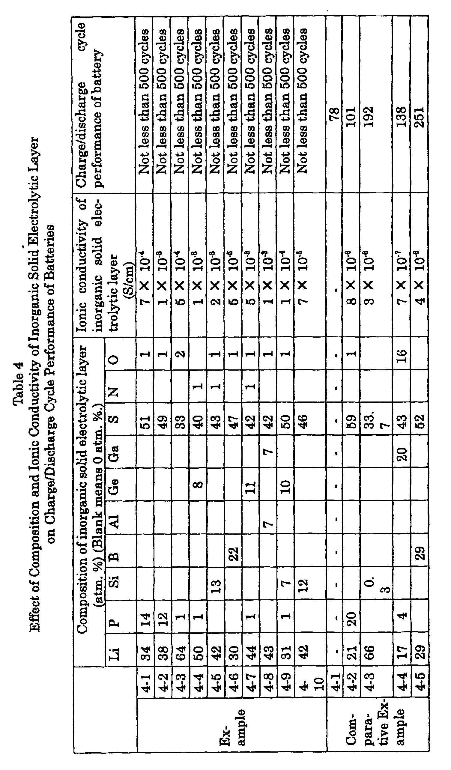
- Example 4-1 the composition and ionic conductivity of the inorganic solid electrolytic layer were changed for experimentation. Addition and content adjustment of the nitrogen atoms in the inorganic solid electrolytic layer were performed by adjusting the nitrogen-gas concentration in the introduced gas in the RF magnetron sputtering process. The charge and discharge-cycle performance of the produced batteries was examined under the same conditions as in Example 4-1. The results are also shown in Table 4.
- Example 4-1 In the battery constitution shown in Example 4-1, the inorganic solid electrolytic layer formed on the metallic-lithium negative electrode was removed for comparative experimentation. A charge and discharge-cycle test was carried out under the same conditions as in Example 4-1. The results are shown in the row "Comparative Example 4-1" in Table 4. The current efficiency was as low as in the order of 90% from the beginning of the charge and discharge. When the number of cycles exceeds 78, a voltage drop attributable to minute internal short circuits became measurable and the capacity further decreased considerably.
- Example 4-1 In the battery constitution and composition of the inorganic solid electrolyte in Example 4-1, only the thickness of the inorganic solid electrolytic layer was changed for experimentation. Charge and discharge-cycle tests were carried out on the produced batteries. The results are shown in Table 5. When the inorganic solid electrolytic layer has a thickness in the range of 50 nm to 50 ⁇ m, the battery caused no internal short circuit and showed no reduction in capacity after the completion of 500 cycles.
- Example 4-1 In the battery constitution in Example 4-1, only the thickness of the inorganic solid electrolytic layer was changed so as to fall outside the range of the thickness in Examples 4-11 to 4-15. An experiment similar to that in Examples 4-11 to 4-15 was carried out to examine the charge and discharge-cycle performance of the produced batteries. The results are also shown in Table 5. As can be seen in the result of Comparative Example 4-8, when the thickness was 60 ⁇ m, the current efficiency showed an insufficient value as low as 95% from the beginning of the charge and discharge cycles. However, the current efficiency showed no change even after the completion of 500 cycles.
- the composition of the positive electrode-side layer made of an amorphous inorganic solid electrolyte was changed to examine the stability of the inorganic solid electrolyte in the air.
- the battery performance was also examined with a constitution similar to that of the battery explained in Example 4-1.
- the negative electrode-side inorganic solid electrolytic layer (also amorphous)had the same composition as in Example 4-7.
- the positive electrode-side and negative electrode-side layers had a thickness of 50 nm and 1 ⁇ m, respectively. The obtained results are shown in Table 6. Each of these examples showed excellent stability.
- the batteries were satisfactory in showing the intended performance. After the completion of 500 cycles, the batteries caused no internal short circuits and showed no decrease in capacity.
- the composition of the positive electrode-side layer made of an amorphous inorganic solid electrolyte was changed from that in Examples 4-16 to 4-18 to examine the stability of the inorganic solid electrolyte in the air.
- the battery performance was also examined with a constitution similar to that of the battery explained in Example 4-1.
- the negative electrode-side inorganic solid electrolytic layer (also amorphous) had the same composition as in Example 4-7.
- Table 6 Both comparative examples were extremely unstable and their battery performance deteriorated significantly.
- the thickness of the positive electrode-side amorphous inorganic solid electrolytic layer was changed to examine the stability of the inorganic solid electrolyte in the air.
- the battery performance was also examined with a constitution similar to that of the battery in Example 4-16.
- the negative electrode-side inorganic solid electrolytic layer (also amorphous) had the same composition as in Example 4-7.
- the obtained results are shown in Table 7. Both examples showed excellent stability.
- the batteries were satisfactory in showing the intended performance. After the completion of 500 cycles, the batteries caused no internal short circuits and showed no reduction in capacity.
- the thickness of the positive electrode-side amorphous inorganic solid electrolytic layer was changed so as to fall outside the range of the thickness in Examples 4-19 and 4-20 to examine the stability of the inorganic solid electrolyte in the air.
- the battery performance was also examined with a constitution similar to that in Example 4-16.
- the negative electrode-side inorganic solid electrolytic layer (also amorphous) had the same composition as in Example 4-7.
- the obtained results are also shown in Table 7. Both comparative examples were extremely unstable and their battery performance deteriorated significantly.
- This example examined the effect of pretreatment of the metallic lithium as the negative electrode.
- the surface of the metallic lithium as the negative electrode was presputtered in an argon atmosphere with an RF magnetron-sputtering apparatus to remove an oxide layer unavoidably existing on the surface of the metallic lithium. Then, an inorganic solid electrolytic layer was formed on the surface of the metallic lithium.
- the electrolytic layer 2.5 ⁇ m in thickness, had a composition of Li (39.4 atm. %), P (0.3 atm. %), B (16.0 atm. %), S (43.3 atm. %), and O (1.1 atm. %).
- a lithium secondary battery was produced by using the foregoing negative electrode with a battery constitution similar to that in Examples 1-1 to 1-5. The charge and discharge-cycle performance of the battery was examined at a constant current of 17.2 mA. After the completion of 500 cycles, the battery caused no internal short circuit and showed no reduction in capacity.
- the surface of the metallic lithium as the negative electrode was presputtered in an atmosphere containing H 2 S with an RF magnetron-sputtering apparatus to remove an oxide layer unavoidably existing on the surface of the metallic lithium for forming a lithium sulfide layer concurrently. Then, an inorganic solid electrolytic layer was formed on the surface of the lithium sulfide layer
- the electrolytic layer 10 ⁇ m in thickness, had a composition of Li (38.2 atm. %), P (12.2 atm. %), S (48.6 atm. %), and O (1.0 atm. %).
- a lithium secondary battery was produced by using the foregoing negative electrode with a battery constitution similar to that in Example 4-1. The charge and discharge-cycle performance of the battery was examined at a constant current of 17.2 mA. After the completion of 500 cycles, the battery caused no internal short circuit and showed no reduction in capacity.
- the surface of the metallic lithium as the negative electrode was presputtered in a nitrogen atmosphere with an RF magnetron-sputtering apparatus to remove an oxide layer unavoidably existing on the surface of the metallic lithium for forming a lithium nitride layer concurrently. Then, an inorganic solid electrolytic film was formed on the surface of the lithium nitride layer.
- the electrolytic layer. 1 ⁇ m in thickness had a composition of Li (42.3 atm. %), P (0.3 atm. %), Si (11.8 atm. %), S (44.3 atm. %), and O (1.3 atm. %).
- a lithium secondary battery was produced by using the foregoing negative electrode with a battery constitution similar to that in Example 4-1. The charge and discharge-cycle performance of the battery was examined at a constant current of 17.2 mA. After the completion of 500 cycles, the battery caused no internal short circuit and showed no reduction in capacity.
- the present invention enables the suppression of short circuits caused by the generation of dendrites from the metallic-lithium negative electrode. Consequently, the present invention can offer a highly stable and safe lithium secondary battery that has high energy density and excellent charge and discharge-cycle performance.
Landscapes
- Chemical & Material Sciences (AREA)
- General Chemical & Material Sciences (AREA)
- Chemical Kinetics & Catalysis (AREA)
- Electrochemistry (AREA)
- Engineering & Computer Science (AREA)
- Manufacturing & Machinery (AREA)
- General Physics & Mathematics (AREA)
- Condensed Matter Physics & Semiconductors (AREA)
- Inorganic Chemistry (AREA)
- Physics & Mathematics (AREA)
- Secondary Cells (AREA)
- Battery Electrode And Active Subsutance (AREA)
- Conductive Materials (AREA)
Abstract
Description
- (a) reduction in the amount of the organic electrolysis solution;
- (b) suppression of the growth of metallic-lithium dendrites on the negative electrode;
- (c) prevention of the contact with the positive electrode and suppression of the reaction with the electrolysis solution, both resulting from the covering effect on the surface of the negative electrode.
| Thickness of negative electrode (µm) | Thickness of electrolytic layer (µm) | Thickness of positive electrode (µm) | Density of current capacity (Ah/cm2) | Time needed for charging (h) | Result of charge/discharge cycle test (1,000 cycles) |
| 0.1 | 10 | 0.2 | 0.02 | 0.004 | - |
| 1 | 10 | 2 | 0.2 | 0.04 | |
| 10 | 10 | 20 | 2 | 0.4 | |
| 100 | 10 | 400 | 20 | 4 | |
| 500 | 10 | 1,500 | 100 | 20 | |
| 50 | 0.04 | 300 | 10 | - | Short-circuited at 300 cycles |
| 50 | 1 | 300 | 10 | Stable | |
| 50 | 10 | 300 | 10 | Stable | |
| 50 | 50 | 300 | 10 | Stable | |
| 50 | 100 | 300 | 10 | Stable |
| Surface roughness of negative electrode (Rmax/µm) | Thickness of electrolytic layer (µm) | Presence or absence of pinholes in electrolytic layer | Result of charge/discharge cycle test (1,000 cycles) |
| 0.001 | 10 | Absent | Stable |
| 0.005 | 10 | Absent | Stable |
| 0.01 | 10 | Absent | Stable |
| 0.1 | 10 | Absent | Stable |
| 1 | 10 | Absent | Stable |
| 3 | 10 | Absent | Stable |
| 5 | 10 | Absent | Stable |
| 7 | 60 | Present | Short-circuited at 300 cycles |
| Thickness of sulfur-containing layer (µm) | Thickness of oxide-containing layer (µm) | |
| 2 | 0.1 | o ○ |
| 10 | 1 | o ○ |
| 15 | 1.7 | o ○ |
| 20 | 1.5 | o ○ |
| 10 | 2 | o ○ |
| 10 | 0.05 | ○ |
| 10 | 2.5 | ○ |
| 1 | 2.5 | X |
| 0.5 | 1 | X |
| 0.5 | 2.5 | X |
| Effect of Thickness of Inorganic Solid Electrolytic Layer on Battery Performance | |||
| Layer thickness | Charge/discharge-cycle performance | ||
| Example | 4-11 | 50 nm | Not less than 500 cycles |
| 4-12 | 100 nm | Not less than 500 cycles | |
| 4-13 | 1.5 µm | Not less than 500 cycles | |
| 4-14 | 35 µm | Not less than 500 cycles | |
| 4-15 | 50 µm | Not less than 500 cycles | |
| Comparative Example | 4-6 | 20 nm | 113 |
| 4-7 | 40 nm | 156 | |
| 4-8 | 60 µm | Not less than 500 cycles (However, current efficiency was 95%.) |
| Effect of Composition of Inorganic Solid Electrolytic Layer in Dual-Layer Structure on Battery Performance | ||||||
| Composition of positive electrode-side layer (atm. %) | Stability in air | |||||
| Li | P | O | N | |||
| Example | 4-16 | 37.5 | 12.5 | 50 | 0 | No change in one month |
| 4-17 | 45.5 | 9.8 | 39.4 | 5.3 | No change in one month | |
| 4-18 | 50 | 8.3 | 33.3 | 8.3 | No change in one month | |
| Comparative Example | 4-9 | 53.6 | 7.1 | 10.7 | 28.6 | After two hours, color change to white was observed and lithium-ion conductivity reduced. |
| 4-10 | 27.5 | 22.5 | 50 | 0 | No change in one month; however, current efficiency reduced in charge/discharge test. |
| Effect of Thickness of Positive Electrode-Side Inorganic Solid Electrolytic Layer in Dual-Layer Structure on Battery Performance | |||
| Thickness of positive electrode-side inorganic solid electrolytic layer | Stability in air | ||
| Example | 4-19 | 10 nm | No change in one month |
| 4-20 | 25 µm | No change in one month | |
| Comparative Example | 4-11 | 5 nm | After one hour, color change to white was observed and lithium-ion conductivity reduced. |
| 4-12 | 30 µm | No change in one month; however, current efficiency reduced in charge/discharge test. |
Claims (33)
- A lithium secondary battery comprising an electrolytic layer, a positive electrode, and a negative electrode that is made of a lithium-containing material, in which battery:(a) the electrolytic layer is made of an inorganic solid electrolyte; and(b) the positive electrode contains an organic high polymer.
- The lithium secondary battery as defined in claim 1, wherein the electrolytic layer has a lithium-ion conductivity of 1 × 10⁻⁵ S/cm or more at 25 °C.
- The lithium secondary battery as defined in claim 1, wherein the electrolytic layer has a lithium-ion conductivity of 5 × 10⁻⁵ S/cm or more at 25 °C.
- The lithium secondary battery as defined in claim 1, wherein the electrolytic layer is made of an amorphous body.
- The lithium secondary battery as defined in claim 1, wherein the electrolytic layer contains at least one type selected from the group consisting of oxygen, nitrogen, sulfide, and oxynitride.
- The lithium secondary battery as defined in claim 5, wherein:(a) the sulfide is composed of at least one type selected from the group consisting of Li2S, a compound between Li2S and SiS2, a compound between Li2S and GeS2, and a compound between Li2S and Ga2S3; and(b) the oxynitride is composed of at least one type selected from the group consisting of Li3PO4-xN2x/3, Li4SiO4-xN2x/3, Li4GeO4-xN2x/3 (where 0 < X < 4), and Li3BO3-xN2x/3 (where 0 < X < 3).
- The lithium secondary battery as defined in claim 1, wherein the electrolytic layer contains:(a) an Li constituent not less than 30 atm. % and not more than 65 atm. %;(b) at least one type of element selected from the group consisting of sulfur, silicon, boron, germanium, and gallium; and(c) sulfur.
- The lithium secondary battery as defined in claim 7, wherein the electrolytic layer contains at least one element selected from the group consisting of oxygen and nitrogen.
- The lithium secondary battery as defined in claim 1, wherein the electrolytic layer has a thickness not less than 50 nm and not more than 50 µm.
- The lithium secondary battery as defined in claim 1, wherein the electrolytic layer consists of two layers that are a positive electrode-side layer and a negative electrode-side layer.
- The lithium secondary battery as defined in claim 10, wherein:(a) the negative electrode-side layer is a film made of a lithium ion-conductive compound containing sulfide; and(b) the positive electrode-side layer is a film made of a lithium ion-conductive compound containing oxide.
- The lithium secondary battery as defined in claim 10, wherein:(a) the electrolytic layer consisting of two layers has a total thickness not less than 2 µm and not more than 22 µm; and(b) the positive electrode-side layer has a thickness not less than 0.1 µm and not more than 2 µm.
- The lithium secondary battery as defined in claim 10, wherein:(a) the negative electrode-side layer contains lithium sulfide and silicon sulfide; and(b) the positive electrode-side layer contains at least one type selected from the group consisting of a phosphate compound and a titanate compound.
- The lithium secondary battery as defined in claim 10, wherein the positive electrode-side layer contains:(a) an Li constituent not less than 30 atm. % and not more than 50 atm. %;(b) phosphorus; and(c) at least one element selected from the group consisting of oxygen and nitrogen.
- The lithium secondary battery as defined in claim 10, wherein the positive electrode-side layer has a thickness not less than 1% and not more than 50% of the thickness of the negative electrode-side layer.
- The lithium secondary battery as defined in claim 10, wherein the positive electrode-side layer has a thickness not less than 10 nm and not more than 25 µm.
- The lithium secondary battery as defined in claim 10, wherein:(a) the positive electrode contains inorganic solid electrolytic particles having lithium-ion conductivity; and(b) the inorganic solid electrolytic particles have an ionic conductivity of 10-3 S/cm or more.
- The lithium secondary battery as defined in claim 1, wherein the organic high polymer contained in the positive electrode is a disulfide-family high polymer containing polyaniline.
- The lithium secondary battery as defined in claim 1, wherein the organic high polymer contained in the positive electrode contains one type of lithium salt selected from the group consisting of LiPF6 and LiCF3SO3.
- The lithium secondary battery as defined in claim 1, wherein the positive electrode contains an organic electrolysis solution.
- The lithium secondary battery as defined in claim 20, wherein the organic electrolysis solution contained in the positive electrode has a lithium ion-conductivity lower than that of the inorganic solid electrolyte that constitutes the electrolytic layer.
- The lithium secondary battery as defined in claim 20, wherein the organic electrolysis solution contained in the positive electrode:(a) comes into contact with the lithium-containing material that constitutes the negative electrode; and(b) thereby reduces the ionic conductivity of the organic electrolysis solution in the vicinity of the contact portion to a value lower than that of the inorganic solid electrolyte.
- The lithium secondary battery as defined in claim 20, wherein the organic solvent contained in the organic electrolysis solution contained in the positive electrode:(a) comes into contact with the lithium-containing material that constitutes the negative electrode; and(b) thereby gasifies in the vicinity of the contact portion.
- The lithium secondary battery as defined in claim 20, wherein the organic solvent contained in the organic electrolysis solution contained in the positive electrode:(a) comes into contact with the lithium-containing material that constitutes the negative electrode; and(b) thereby solidifies in the vicinity of the contact portion.
- The lithium secondary battery as defined in claim 20, wherein the organic solvent contained in the organic electrolysis solution contained in the positive electrode:(a) comes into contact with the lithium-containing material that constitutes the negative electrode; and(b) thereby increases the viscosity of the organic electrolysis solution in the vicinity of the contact portion.
- The lithium secondary battery as defined in claim 20, wherein the organic solvent contained in the organic electrolysis solution contained in the positive electrode contains a sulfolane-family compound.
- The lithium secondary battery as defined in claim 20, wherein the organic solvent contained in the organic electrolysis solution contained in the positive electrode contains a chain carboxylic ester family.
- The lithium secondary battery as defined in claim 20, wherein the organic solvent contained in the organic electrolysis solution contained in the positive electrode contains at least one type of compound selected from the group consisting of compounds having a nitrile group and compounds having olefinic linkage.
- The lithium secondary battery as defined in claim 1, wherein the negative electrode has a surface roughness not less than 0.01 µm and not more than 5 µm in the value of Rmax.
- The lithium secondary battery as defined in claim 1, wherein the negative electrode:(a) has at its electrolytic-layer side a layer of a metal that forms an alloy or intermetallic compound with lithium; and(b) has a multilayer or a graded structure in composition.
- The lithium secondary battery as defined in claim 1, wherein the negative electrode:(a) has no oxide layer on its surface; and(b) has a sulfide or nitride layer on its surface.
- The lithium secondary battery as defined in claim 1, wherein the electrolytic layer is formed directly on the surface of the negative electrode without the medium of an oxide layer.
- The lithium secondary battery as defined in claim 1, wherein:(a) the positive and negative electrodes are each provided with a collector; and(b) the electrolytic layer is formed directly on the negative electrode-side collector without providing a lithium-containing material as the negative electrode.
Applications Claiming Priority (7)
| Application Number | Priority Date | Filing Date | Title |
|---|---|---|---|
| JP34459398 | 1998-12-03 | ||
| JP34459398 | 1998-12-03 | ||
| JP773699 | 1999-01-14 | ||
| JP773699 | 1999-01-14 | ||
| JP7873399 | 1999-03-24 | ||
| JP7873399 | 1999-03-24 | ||
| PCT/JP1999/006668 WO2000033409A1 (en) | 1998-12-03 | 1999-11-29 | Lithium storage battery |
Publications (3)
| Publication Number | Publication Date |
|---|---|
| EP1052718A1 true EP1052718A1 (en) | 2000-11-15 |
| EP1052718A4 EP1052718A4 (en) | 2005-03-30 |
| EP1052718B1 EP1052718B1 (en) | 2007-08-01 |
Family
ID=27277731
Family Applications (1)
| Application Number | Title | Priority Date | Filing Date |
|---|---|---|---|
| EP99973180A Expired - Lifetime EP1052718B1 (en) | 1998-12-03 | 1999-11-29 | Lithium storage battery |
Country Status (5)
| Country | Link |
|---|---|
| US (1) | US6365300B1 (en) |
| EP (1) | EP1052718B1 (en) |
| CA (1) | CA2319460C (en) |
| DE (1) | DE69936706T2 (en) |
| WO (1) | WO2000033409A1 (en) |
Cited By (14)
| Publication number | Priority date | Publication date | Assignee | Title |
|---|---|---|---|---|
| EP1424743A1 (en) * | 2002-11-29 | 2004-06-02 | Kabushiki Kaisha Ohara | Lithium ion secondary battery with Li ion conductive inorganic solid electrolyte and a method for manufacturing the same |
| EP1162675A3 (en) * | 2000-06-08 | 2004-09-08 | Sumitomo Electric Industries, Ltd. | Negative electrode of lithium secondary battery |
| US6818356B1 (en) * | 2002-07-09 | 2004-11-16 | Oak Ridge Micro-Energy, Inc. | Thin film battery and electrolyte therefor |
| US7150943B2 (en) | 2001-02-28 | 2006-12-19 | Sumitomo Electric Industries, Ltd. | Inorganic solid electrolyte and lithium cell component |
| EP1739769A1 (en) * | 2005-06-28 | 2007-01-03 | Sumitomo Electric Industries, Ltd. | Lithium secondary battery anode member and method for manufacturing the same |
| EP1667272A4 (en) * | 2003-06-27 | 2008-05-14 | Matsushita Electric Industrial Co Ltd | SOLID ELECTROLYTE AND ENTIRELY SOLID BATTERY USING THE SOLID ELECTROLYTE |
| US7410730B2 (en) | 2002-07-09 | 2008-08-12 | Oak Ridge Micro-Energy, Inc. | Thin film battery and electrolyte therefor |
| EP1675206A4 (en) * | 2003-06-27 | 2009-04-08 | Panasonic Corp | SOLID ELECTROLYTE AND FULLY SOLID BATTERY OPERATING WITH THIS ELECTROLYTE |
| EP1217682A3 (en) * | 2000-12-13 | 2009-08-26 | Sumitomo Electric Industries, Ltd. | Method of forming thin film of inorganic solid electrolyte |
| EP1732152A4 (en) * | 2004-04-01 | 2010-01-20 | Sumitomo Electric Industries | NEGATIVE ELECTRODE ELEMENT FOR LITHIUM SECONDARY BATTERY AND PROCESS FOR PRODUCING THE SAME |
| CN101933189A (en) * | 2008-01-23 | 2010-12-29 | 无穷动力解决方案股份有限公司 | Thin Film Electrolytes for Thin Film Batteries |
| WO2015067474A3 (en) * | 2013-11-08 | 2015-07-02 | Robert Bosch Gmbh | Electrochemical cell and method for the production thereof |
| RU2569670C1 (en) * | 2012-02-28 | 2015-11-27 | Ниссан Мотор Ко., Лтд. | Accumulator battery with non-aqueous electrolyte |
| CN108923062A (en) * | 2018-06-25 | 2018-11-30 | 江苏大学 | Organic/inorganic composite solid electrolyte and application based on quasi-one-dimensional oxides |
Families Citing this family (76)
| Publication number | Priority date | Publication date | Assignee | Title |
|---|---|---|---|---|
| JP3412616B2 (en) * | 2000-07-19 | 2003-06-03 | 住友電気工業株式会社 | Method for producing negative electrode for lithium secondary battery |
| US20020142217A1 (en) * | 2001-03-27 | 2002-10-03 | Amatucci Glenn G. | Germanium nitride electrode material for high capacity rechargeable lithium battery cell |
| US7404877B2 (en) * | 2001-11-09 | 2008-07-29 | Springworks, Llc | Low temperature zirconia based thermal barrier layer by PVD |
| US20030175142A1 (en) * | 2002-03-16 | 2003-09-18 | Vassiliki Milonopoulou | Rare-earth pre-alloyed PVD targets for dielectric planar applications |
| US6884327B2 (en) * | 2002-03-16 | 2005-04-26 | Tao Pan | Mode size converter for a planar waveguide |
| US7378356B2 (en) * | 2002-03-16 | 2008-05-27 | Springworks, Llc | Biased pulse DC reactive sputtering of oxide films |
| US8431264B2 (en) | 2002-08-09 | 2013-04-30 | Infinite Power Solutions, Inc. | Hybrid thin-film battery |
| US8394522B2 (en) | 2002-08-09 | 2013-03-12 | Infinite Power Solutions, Inc. | Robust metal film encapsulation |
| US8445130B2 (en) | 2002-08-09 | 2013-05-21 | Infinite Power Solutions, Inc. | Hybrid thin-film battery |
| US8236443B2 (en) | 2002-08-09 | 2012-08-07 | Infinite Power Solutions, Inc. | Metal film encapsulation |
| US20070264564A1 (en) | 2006-03-16 | 2007-11-15 | Infinite Power Solutions, Inc. | Thin film battery on an integrated circuit or circuit board and method thereof |
| US8021778B2 (en) | 2002-08-09 | 2011-09-20 | Infinite Power Solutions, Inc. | Electrochemical apparatus with barrier layer protected substrate |
| US8404376B2 (en) | 2002-08-09 | 2013-03-26 | Infinite Power Solutions, Inc. | Metal film encapsulation |
| US7993773B2 (en) | 2002-08-09 | 2011-08-09 | Infinite Power Solutions, Inc. | Electrochemical apparatus with barrier layer protected substrate |
| AU2003261463A1 (en) * | 2002-08-27 | 2004-03-19 | Symmorphix, Inc. | Optically coupling into highly uniform waveguides |
| US6994933B1 (en) | 2002-09-16 | 2006-02-07 | Oak Ridge Micro-Energy, Inc. | Long life thin film battery and method therefor |
| JP2004206942A (en) * | 2002-12-24 | 2004-07-22 | Ion Engineering Research Institute Corp | All-solid lithium battery |
| US7205662B2 (en) * | 2003-02-27 | 2007-04-17 | Symmorphix, Inc. | Dielectric barrier layer films |
| KR100508945B1 (en) * | 2003-04-17 | 2005-08-17 | 삼성에스디아이 주식회사 | Negative electrode for lithium battery, method of preparing same, and lithium battery comprising same |
| US7238628B2 (en) * | 2003-05-23 | 2007-07-03 | Symmorphix, Inc. | Energy conversion and storage films and devices by physical vapor deposition of titanium and titanium oxides and sub-oxides |
| US8728285B2 (en) | 2003-05-23 | 2014-05-20 | Demaray, Llc | Transparent conductive oxides |
| JP4605389B2 (en) * | 2003-07-31 | 2011-01-05 | 日本電気株式会社 | Lithium ion secondary battery |
| KR100570677B1 (en) * | 2003-09-26 | 2006-04-12 | 삼성에스디아이 주식회사 | Lithium secondary battery |
| KR100790280B1 (en) * | 2004-03-30 | 2008-01-02 | 마쯔시다덴기산교 가부시키가이샤 | Nonaqueous Electrolyte Secondary Battery |
| US7959769B2 (en) | 2004-12-08 | 2011-06-14 | Infinite Power Solutions, Inc. | Deposition of LiCoO2 |
| KR101127370B1 (en) | 2004-12-08 | 2012-03-29 | 인피니트 파워 솔루션스, 인크. | Deposition of licoo2 |
| US7838133B2 (en) * | 2005-09-02 | 2010-11-23 | Springworks, Llc | Deposition of perovskite and other compound ceramic films for dielectric applications |
| KR101295927B1 (en) * | 2005-10-21 | 2013-08-13 | 파나소닉 주식회사 | battery |
| CN101523571A (en) | 2006-09-29 | 2009-09-02 | 无穷动力解决方案股份有限公司 | Masking and material confinement of a battery layer deposited on a flexible substrate |
| US8197781B2 (en) | 2006-11-07 | 2012-06-12 | Infinite Power Solutions, Inc. | Sputtering target of Li3PO4 and method for producing same |
| JP4893254B2 (en) * | 2006-11-15 | 2012-03-07 | トヨタ自動車株式会社 | Lithium secondary battery manufacturing method and lithium secondary battery |
| JP2008152925A (en) | 2006-12-14 | 2008-07-03 | Sumitomo Electric Ind Ltd | Battery structure and lithium secondary battery using the same |
| JP5226967B2 (en) * | 2007-04-27 | 2013-07-03 | 株式会社オハラ | Lithium secondary battery and electrode for lithium secondary battery |
| US9093707B2 (en) * | 2007-06-11 | 2015-07-28 | Alliance For Sustainable Energy, Llc | MultiLayer solid electrolyte for lithium thin film batteries |
| JP5323837B2 (en) * | 2007-09-12 | 2013-10-23 | エルジー・ケム・リミテッド | Non-aqueous electrolyte lithium secondary battery |
| US8268488B2 (en) | 2007-12-21 | 2012-09-18 | Infinite Power Solutions, Inc. | Thin film electrolyte for thin film batteries |
| CN101903560B (en) | 2007-12-21 | 2014-08-06 | 无穷动力解决方案股份有限公司 | Method for sputter targets for electrolyte films |
| US8518581B2 (en) | 2008-01-11 | 2013-08-27 | Inifinite Power Solutions, Inc. | Thin film encapsulation for thin film batteries and other devices |
| WO2009124191A2 (en) | 2008-04-02 | 2009-10-08 | Infinite Power Solutions, Inc. | Passive over/under voltage control and protection for energy storage devices associated with energy harvesting |
| KR101047865B1 (en) * | 2008-05-21 | 2011-07-08 | 지에스나노텍 주식회사 | Solid electrolyte, preparation method thereof and thin film battery comprising same |
| JP2012500610A (en) | 2008-08-11 | 2012-01-05 | インフィニット パワー ソリューションズ, インコーポレイテッド | Energy device with integrated collector surface and method for electromagnetic energy acquisition |
| CN102150185B (en) | 2008-09-12 | 2014-05-28 | 无穷动力解决方案股份有限公司 | Energy device with integral conductive surface for data communication via electromagnetic energy and method thereof |
| WO2010042594A1 (en) | 2008-10-08 | 2010-04-15 | Infinite Power Solutions, Inc. | Environmentally-powered wireless sensor module |
| KR20100098543A (en) * | 2008-12-01 | 2010-09-07 | 도요타지도샤가부시키가이샤 | Solid electrolyte battery, vehicle, battery-mounted apparatus, and method for production of solid electrolyte battery |
| CN102576828B (en) | 2009-09-01 | 2016-04-20 | 萨普拉斯特研究有限责任公司 | Printed circuit board with integrated thin-film battery |
| US8865354B2 (en) | 2010-03-30 | 2014-10-21 | West Virginia University | Inorganic solid electrolyte glass phase composite and a battery containing an inorganic solid electrolyte glass phase composite |
| JPWO2011148824A1 (en) * | 2010-05-25 | 2013-07-25 | 住友電気工業株式会社 | Nonaqueous electrolyte battery and manufacturing method thereof |
| EP2577777B1 (en) | 2010-06-07 | 2016-12-28 | Sapurast Research LLC | Rechargeable, high-density electrochemical device |
| JP4948659B1 (en) * | 2011-04-12 | 2012-06-06 | 三井金属鉱業株式会社 | Method for producing lithium sulfide for solid electrolyte material of lithium ion battery |
| KR101440886B1 (en) | 2011-06-22 | 2014-09-18 | 삼성에스디아이 주식회사 | Solid electrolyte, manufacturing method thereof, and lithium battery employing the same |
| US11996517B2 (en) * | 2011-06-29 | 2024-05-28 | Space Charge, LLC | Electrochemical energy storage devices |
| JP5758753B2 (en) * | 2011-09-09 | 2015-08-05 | 株式会社リコー | Non-aqueous electrolyte secondary battery |
| CN102738442B (en) * | 2012-06-14 | 2016-04-20 | 复旦大学 | A kind of high energy density charge-discharge lithium battery |
| DE102012022607A1 (en) * | 2012-11-19 | 2014-05-22 | Fraunhofer-Gesellschaft zur Förderung der angewandten Forschung e.V. | Solid / gel electrolyte accumulator with inorganic-organic hybrid polymer binder and process for its preparation |
| US9531010B2 (en) * | 2012-12-14 | 2016-12-27 | Indiana University Research And Technology Corporation | Paper-based lithium-ion batteries |
| US12261284B2 (en) * | 2013-03-15 | 2025-03-25 | Sion Power Corporation | Protective structures for electrodes |
| EP2997611B1 (en) | 2013-05-15 | 2026-04-22 | QuantumScape Battery, Inc. | Solid state catholyte or electrolyte for battery |
| WO2015023854A1 (en) * | 2013-08-15 | 2015-02-19 | Robert Bosch Gmbh | Hybrid ionic electronic energy storage device |
| US9859560B2 (en) | 2014-06-04 | 2018-01-02 | Quantumscape Corporation | Electrode materials with mixed particle sizes |
| EP3353844B1 (en) | 2015-03-27 | 2022-05-11 | Mason K. Harrup | All-inorganic solvents for electrolytes |
| WO2016210371A1 (en) | 2015-06-24 | 2016-12-29 | Quantumscape Corporation | Composite electrolytes |
| KR102765039B1 (en) | 2015-12-04 | 2025-02-11 | 퀀텀스케이프 배터리, 인코포레이티드 | Electrolyte and catholyte compositions comprising lithium, phosphorus, sulfur and iodine, electrolyte membranes for electrochemical devices, and an annealing method for producing these electrolytes and catholytes. |
| CN105514491B (en) * | 2015-12-29 | 2018-06-26 | 湖州创亚动力电池材料有限公司 | A kind of preparation of all solid state inoganic solids lithium-ion electrolyte |
| JP6704457B2 (en) | 2016-02-26 | 2020-06-03 | エルジー・ケム・リミテッド | Lithium secondary battery |
| DE102016214399A1 (en) * | 2016-08-04 | 2018-02-08 | Bayerische Motoren Werke Aktiengesellschaft | Electrochemical cell and method of making the electrochemical cell |
| US11342630B2 (en) | 2016-08-29 | 2022-05-24 | Quantumscape Battery, Inc. | Catholytes for solid state rechargeable batteries, battery architectures suitable for use with these catholytes, and methods of making and using the same |
| US10707531B1 (en) | 2016-09-27 | 2020-07-07 | New Dominion Enterprises Inc. | All-inorganic solvents for electrolytes |
| JP6729796B2 (en) * | 2017-04-04 | 2020-07-22 | 株式会社村田製作所 | All solid state batteries, electronic devices, electronic cards, wearable devices and electric vehicles |
| KR102281373B1 (en) | 2018-04-26 | 2021-07-22 | 주식회사 엘지에너지솔루션 | Cathode for solid electrolyte battery and solid electrolyte battery including the same |
| CN110767894A (en) * | 2018-07-25 | 2020-02-07 | 中能中科(天津)新能源科技有限公司 | Solid electrolyte-lithium complex, method for preparing same, and all-solid lithium secondary battery comprising same |
| EP4099463B1 (en) | 2018-08-30 | 2025-03-05 | GS Yuasa International Ltd. | Sulfide solid electrolyte and all-solid-state battery |
| KR102864154B1 (en) | 2018-10-30 | 2025-09-25 | 주식회사 엘지에너지솔루션 | Lithium secondary battery |
| KR102745343B1 (en) * | 2018-10-30 | 2024-12-23 | 삼성전자주식회사 | All Solid secondary battery, and method for preparing all solid secondary battery |
| EP3754760B1 (en) | 2018-10-31 | 2026-02-18 | LG Energy Solution, Ltd. | Lithium secondary battery |
| US12230782B2 (en) | 2018-11-02 | 2025-02-18 | Lg Energy Solution, Ltd. | Lithium secondary battery |
| JP7710738B2 (en) * | 2019-10-25 | 2025-07-22 | 株式会社グリナジー | Lithium metal negative electrode structure, electrochemical device including the same, and method for producing the lithium metal negative electrode structure |
Family Cites Families (16)
| Publication number | Priority date | Publication date | Assignee | Title |
|---|---|---|---|---|
| CA1266086A (en) | 1985-06-28 | 1990-02-20 | James Robert Akridge | Vitreous solid lithium cation conductive electrolyte |
| US4599284A (en) * | 1985-10-01 | 1986-07-08 | Union Carbide Corporation | Vitreous phosphorus oxide-sulfide solid lithium electrolyte |
| US5217826A (en) | 1990-07-31 | 1993-06-08 | Matsushita Electric Industrial Co., Ltd. | Lithium-ion conducting solid electrolyte |
| US5085953A (en) | 1990-09-18 | 1992-02-04 | Eveready Battery Company, Inc. | Vitreous compositions based on Li3 PO4 and LiPO3 as network formers and network modifiers |
| US5494762A (en) | 1992-01-16 | 1996-02-27 | Nippondenso Co., Ltd. | Non-aqueous electrolyte lithium secondary cell |
| JPH06290773A (en) | 1993-03-30 | 1994-10-18 | Nippondenso Co Ltd | Lithium secondary battery |
| JP3530544B2 (en) | 1992-09-14 | 2004-05-24 | キヤノン株式会社 | Rechargeable battery |
| JPH06275314A (en) | 1993-03-23 | 1994-09-30 | Matsushita Electric Ind Co Ltd | Lithium secondary battery |
| US5314765A (en) * | 1993-10-14 | 1994-05-24 | Martin Marietta Energy Systems, Inc. | Protective lithium ion conducting ceramic coating for lithium metal anodes and associate method |
| JPH08195219A (en) * | 1994-11-14 | 1996-07-30 | Matsushita Electric Ind Co Ltd | All solid lithium secondary battery |
| US6025094A (en) * | 1994-11-23 | 2000-02-15 | Polyplus Battery Company, Inc. | Protective coatings for negative electrodes |
| US5686203A (en) * | 1994-12-01 | 1997-11-11 | Fuji Photo Film Co., Ltd. | Non-aqueous secondary battery |
| JPH08329983A (en) | 1995-06-06 | 1996-12-13 | Matsushita Electric Ind Co Ltd | Lithium battery |
| JPH0982329A (en) | 1995-09-12 | 1997-03-28 | Matsushita Electric Ind Co Ltd | Composite electrode containing organic disulfide compound, manufacture thereof, and lithium secondary battery |
| JPH10189047A (en) | 1996-12-27 | 1998-07-21 | Fujikura Ltd | Lithium ion secondary battery |
| WO1999019932A1 (en) * | 1997-10-15 | 1999-04-22 | Moltech Corporation | Non-aqueous electrolyte solvents for secondary cells |
-
1999
- 1999-11-29 DE DE69936706T patent/DE69936706T2/en not_active Expired - Lifetime
- 1999-11-29 CA CA002319460A patent/CA2319460C/en not_active Expired - Fee Related
- 1999-11-29 WO PCT/JP1999/006668 patent/WO2000033409A1/en not_active Ceased
- 1999-11-29 EP EP99973180A patent/EP1052718B1/en not_active Expired - Lifetime
- 1999-11-29 US US09/601,498 patent/US6365300B1/en not_active Expired - Lifetime
Cited By (20)
| Publication number | Priority date | Publication date | Assignee | Title |
|---|---|---|---|---|
| EP1162675A3 (en) * | 2000-06-08 | 2004-09-08 | Sumitomo Electric Industries, Ltd. | Negative electrode of lithium secondary battery |
| EP1217682A3 (en) * | 2000-12-13 | 2009-08-26 | Sumitomo Electric Industries, Ltd. | Method of forming thin film of inorganic solid electrolyte |
| US7150943B2 (en) | 2001-02-28 | 2006-12-19 | Sumitomo Electric Industries, Ltd. | Inorganic solid electrolyte and lithium cell component |
| US7517616B2 (en) | 2001-02-28 | 2009-04-14 | Sumitomo Electric Industries, Ltd. | Inorganic solid electrolyte and lithium cell component |
| US6818356B1 (en) * | 2002-07-09 | 2004-11-16 | Oak Ridge Micro-Energy, Inc. | Thin film battery and electrolyte therefor |
| US7410730B2 (en) | 2002-07-09 | 2008-08-12 | Oak Ridge Micro-Energy, Inc. | Thin film battery and electrolyte therefor |
| EP1424743A1 (en) * | 2002-11-29 | 2004-06-02 | Kabushiki Kaisha Ohara | Lithium ion secondary battery with Li ion conductive inorganic solid electrolyte and a method for manufacturing the same |
| US7736811B2 (en) | 2003-06-27 | 2010-06-15 | Panasonic Corporation | Solid electrolyte and all solid state battery using the same |
| EP1667272A4 (en) * | 2003-06-27 | 2008-05-14 | Matsushita Electric Industrial Co Ltd | SOLID ELECTROLYTE AND ENTIRELY SOLID BATTERY USING THE SOLID ELECTROLYTE |
| EP1675206A4 (en) * | 2003-06-27 | 2009-04-08 | Panasonic Corp | SOLID ELECTROLYTE AND FULLY SOLID BATTERY OPERATING WITH THIS ELECTROLYTE |
| EP1732152A4 (en) * | 2004-04-01 | 2010-01-20 | Sumitomo Electric Industries | NEGATIVE ELECTRODE ELEMENT FOR LITHIUM SECONDARY BATTERY AND PROCESS FOR PRODUCING THE SAME |
| EP1739769A1 (en) * | 2005-06-28 | 2007-01-03 | Sumitomo Electric Industries, Ltd. | Lithium secondary battery anode member and method for manufacturing the same |
| US8709106B2 (en) | 2005-06-28 | 2014-04-29 | Sumitomo Electric Industries, Ltd. | Lithium secondary battery anode member and method for manufacturing the same |
| CN101933189A (en) * | 2008-01-23 | 2010-12-29 | 无穷动力解决方案股份有限公司 | Thin Film Electrolytes for Thin Film Batteries |
| CN101933189B (en) * | 2008-01-23 | 2014-06-25 | 无穷动力解决方案股份有限公司 | Thin film electrolyte for thin film batteries |
| RU2569670C1 (en) * | 2012-02-28 | 2015-11-27 | Ниссан Мотор Ко., Лтд. | Accumulator battery with non-aqueous electrolyte |
| US10224527B2 (en) | 2012-02-28 | 2019-03-05 | Nissan Motor Co., Ltd. | Non-aqueous electrolyte secondary battery |
| WO2015067474A3 (en) * | 2013-11-08 | 2015-07-02 | Robert Bosch Gmbh | Electrochemical cell and method for the production thereof |
| CN108923062A (en) * | 2018-06-25 | 2018-11-30 | 江苏大学 | Organic/inorganic composite solid electrolyte and application based on quasi-one-dimensional oxides |
| CN108923062B (en) * | 2018-06-25 | 2020-09-25 | 江苏大学 | Organic/inorganic composite solid-state electrolytes based on quasi-one-dimensional oxides and their applications |
Also Published As
| Publication number | Publication date |
|---|---|
| EP1052718B1 (en) | 2007-08-01 |
| CA2319460C (en) | 2010-02-02 |
| DE69936706D1 (en) | 2007-09-13 |
| US6365300B1 (en) | 2002-04-02 |
| CA2319460A1 (en) | 2000-06-08 |
| DE69936706T2 (en) | 2008-04-30 |
| WO2000033409A1 (en) | 2000-06-08 |
| EP1052718A4 (en) | 2005-03-30 |
Similar Documents
| Publication | Publication Date | Title |
|---|---|---|
| US6365300B1 (en) | Lithium secondary battery | |
| JP3578015B2 (en) | Lithium secondary battery | |
| US11876223B2 (en) | Negative electrode for lithium metal battery and lithium metal battery comprising same | |
| EP3605670B1 (en) | Method for forming lithium metal and inorganic material composite thin film and method for pre-lithiation of negative electrode for lithium secondary battery by using same | |
| EP3896757B1 (en) | Electrode used for improving battery performance and comprising composite layer with bracket structure and protective layer, and battery | |
| KR20210053862A (en) | Positive electrode material for lithium secondary battery, positive electrode and lithium secondary battery including the same | |
| CN106797021B (en) | Additive for alkali metal-based energy stores | |
| US20130149567A1 (en) | Lithium ion battery with amorphous electrode materials | |
| KR20200050855A (en) | All solid secondary battery and method of manufacturing the same | |
| WO2020214010A1 (en) | Electrolyte membrane for all-solid-state battery and all-solid-state battery comprising same | |
| JP4016344B2 (en) | Lithium secondary battery | |
| KR20240088617A (en) | Positive electrode and lithium secondary battery comprising the same | |
| KR20210059662A (en) | A solid electrolyte mambrane and all solid sate lithium secondary battery including the same | |
| EP0905807B1 (en) | Nonaqueous secondary battery | |
| KR102883390B1 (en) | Methode for manufacturing the lithum metal electrode and lithium metal secondary battery | |
| CN113206219A (en) | Lithium ion battery | |
| EP4376120A1 (en) | Anode active material for lithium secondary battery and lithium secondary battery including the same | |
| EP4682968A1 (en) | Positive electrode for all-solid-state rechargeable battery and all-solid-state rechargeable battery including same | |
| EP4693433A1 (en) | Lithium metal battery, and method for manufacturing lithium metal battery anode included therein | |
| US20250201911A1 (en) | All solid-state battery and method of preparing same | |
| EP4641743A1 (en) | All-solid-state battery | |
| US20260066259A1 (en) | Method Of Preparing Electrode For Secondary Battery | |
| EP4553913A1 (en) | Anode for lithium secondary battery and lithium secondary battery including the same | |
| EP4451451A1 (en) | Separator for secondary battery, method for manufacturing same, and secondary battery | |
| US20250105299A1 (en) | All solid-state battery and all solid-state battery stack |
Legal Events
| Date | Code | Title | Description |
|---|---|---|---|
| PUAI | Public reference made under article 153(3) epc to a published international application that has entered the european phase |
Free format text: ORIGINAL CODE: 0009012 |
|
| 17P | Request for examination filed |
Effective date: 20000816 |
|
| AK | Designated contracting states |
Kind code of ref document: A1 Designated state(s): AT BE CH CY DE DK ES FI FR GB GR IE IT LI LU MC NL PT SE |
|
| RBV | Designated contracting states (corrected) |
Designated state(s): DE FR GB IT NL SE |
|
| A4 | Supplementary search report drawn up and despatched |
Effective date: 20050214 |
|
| RIC1 | Information provided on ipc code assigned before grant |
Ipc: 7H 01M 6/18 B Ipc: 7H 01M 10/40 B Ipc: 7H 01M 4/02 B Ipc: 7H 01M 10/36 A |
|
| 17Q | First examination report despatched |
Effective date: 20060303 |
|
| GRAP | Despatch of communication of intention to grant a patent |
Free format text: ORIGINAL CODE: EPIDOSNIGR1 |
|
| GRAS | Grant fee paid |
Free format text: ORIGINAL CODE: EPIDOSNIGR3 |
|
| GRAA | (expected) grant |
Free format text: ORIGINAL CODE: 0009210 |
|
| AK | Designated contracting states |
Kind code of ref document: B1 Designated state(s): DE FR GB IT NL SE |
|
| REG | Reference to a national code |
Ref country code: GB Ref legal event code: FG4D |
|
| REF | Corresponds to: |
Ref document number: 69936706 Country of ref document: DE Date of ref document: 20070913 Kind code of ref document: P |
|
| REG | Reference to a national code |
Ref country code: SE Ref legal event code: TRGR |
|
| ET | Fr: translation filed | ||
| PLBE | No opposition filed within time limit |
Free format text: ORIGINAL CODE: 0009261 |
|
| STAA | Information on the status of an ep patent application or granted ep patent |
Free format text: STATUS: NO OPPOSITION FILED WITHIN TIME LIMIT |
|
| 26N | No opposition filed |
Effective date: 20080506 |
|
| REG | Reference to a national code |
Ref country code: DE Ref legal event code: R084 Ref document number: 69936706 Country of ref document: DE |
|
| REG | Reference to a national code |
Ref country code: DE Ref legal event code: R079 Ref document number: 69936706 Country of ref document: DE Free format text: PREVIOUS MAIN CLASS: H01M0010360000 Ipc: H01M0010052000 |
|
| REG | Reference to a national code |
Ref country code: GB Ref legal event code: 746 Effective date: 20131125 |
|
| REG | Reference to a national code |
Ref country code: DE Ref legal event code: R084 Ref document number: 69936706 Country of ref document: DE Effective date: 20131125 Ref country code: DE Ref legal event code: R079 Ref document number: 69936706 Country of ref document: DE Free format text: PREVIOUS MAIN CLASS: H01M0010360000 Ipc: H01M0010052000 Effective date: 20131203 |
|
| PGFP | Annual fee paid to national office [announced via postgrant information from national office to epo] |
Ref country code: DE Payment date: 20131127 Year of fee payment: 15 Ref country code: FR Payment date: 20131108 Year of fee payment: 15 Ref country code: GB Payment date: 20131127 Year of fee payment: 15 Ref country code: SE Payment date: 20131112 Year of fee payment: 15 |
|
| PGFP | Annual fee paid to national office [announced via postgrant information from national office to epo] |
Ref country code: NL Payment date: 20131010 Year of fee payment: 15 Ref country code: IT Payment date: 20131024 Year of fee payment: 15 |
|
| REG | Reference to a national code |
Ref country code: DE Ref legal event code: R119 Ref document number: 69936706 Country of ref document: DE |
|
| REG | Reference to a national code |
Ref country code: NL Ref legal event code: V1 Effective date: 20150601 |
|
| REG | Reference to a national code |
Ref country code: SE Ref legal event code: EUG |
|
| GBPC | Gb: european patent ceased through non-payment of renewal fee |
Effective date: 20141129 |
|
| PG25 | Lapsed in a contracting state [announced via postgrant information from national office to epo] |
Ref country code: SE Free format text: LAPSE BECAUSE OF NON-PAYMENT OF DUE FEES Effective date: 20141130 |
|
| REG | Reference to a national code |
Ref country code: FR Ref legal event code: ST Effective date: 20150731 |
|
| PG25 | Lapsed in a contracting state [announced via postgrant information from national office to epo] |
Ref country code: NL Free format text: LAPSE BECAUSE OF NON-PAYMENT OF DUE FEES Effective date: 20150601 |
|
| PG25 | Lapsed in a contracting state [announced via postgrant information from national office to epo] |
Ref country code: GB Free format text: LAPSE BECAUSE OF NON-PAYMENT OF DUE FEES Effective date: 20141129 Ref country code: DE Free format text: LAPSE BECAUSE OF NON-PAYMENT OF DUE FEES Effective date: 20150602 |
|
| PG25 | Lapsed in a contracting state [announced via postgrant information from national office to epo] |
Ref country code: FR Free format text: LAPSE BECAUSE OF NON-PAYMENT OF DUE FEES Effective date: 20141201 |
|
| PG25 | Lapsed in a contracting state [announced via postgrant information from national office to epo] |
Ref country code: IT Free format text: LAPSE BECAUSE OF NON-PAYMENT OF DUE FEES Effective date: 20141129 |