EP1424743A1 - Lithium ion secondary battery with Li ion conductive inorganic solid electrolyte and a method for manufacturing the same - Google Patents
Lithium ion secondary battery with Li ion conductive inorganic solid electrolyte and a method for manufacturing the same Download PDFInfo
- Publication number
- EP1424743A1 EP1424743A1 EP03027366A EP03027366A EP1424743A1 EP 1424743 A1 EP1424743 A1 EP 1424743A1 EP 03027366 A EP03027366 A EP 03027366A EP 03027366 A EP03027366 A EP 03027366A EP 1424743 A1 EP1424743 A1 EP 1424743A1
- Authority
- EP
- European Patent Office
- Prior art keywords
- lithium ion
- solid electrolyte
- secondary battery
- thin film
- ion secondary
- Prior art date
- Legal status (The legal status is an assumption and is not a legal conclusion. Google has not performed a legal analysis and makes no representation as to the accuracy of the status listed.)
- Granted
Links
Images
Classifications
-
- H—ELECTRICITY
- H01—ELECTRIC ELEMENTS
- H01M—PROCESSES OR MEANS, e.g. BATTERIES, FOR THE DIRECT CONVERSION OF CHEMICAL ENERGY INTO ELECTRICAL ENERGY
- H01M10/00—Secondary cells; Manufacture thereof
- H01M10/05—Accumulators with non-aqueous electrolyte
- H01M10/056—Accumulators with non-aqueous electrolyte characterised by the materials used as electrolytes, e.g. mixed inorganic/organic electrolytes
- H01M10/0561—Accumulators with non-aqueous electrolyte characterised by the materials used as electrolytes, e.g. mixed inorganic/organic electrolytes the electrolyte being constituted of inorganic materials only
- H01M10/0562—Solid materials
-
- H—ELECTRICITY
- H01—ELECTRIC ELEMENTS
- H01M—PROCESSES OR MEANS, e.g. BATTERIES, FOR THE DIRECT CONVERSION OF CHEMICAL ENERGY INTO ELECTRICAL ENERGY
- H01M10/00—Secondary cells; Manufacture thereof
- H01M10/04—Construction or manufacture in general
- H01M10/0436—Small-sized flat cells or batteries for portable equipment
-
- H—ELECTRICITY
- H01—ELECTRIC ELEMENTS
- H01M—PROCESSES OR MEANS, e.g. BATTERIES, FOR THE DIRECT CONVERSION OF CHEMICAL ENERGY INTO ELECTRICAL ENERGY
- H01M10/00—Secondary cells; Manufacture thereof
- H01M10/05—Accumulators with non-aqueous electrolyte
- H01M10/052—Li-accumulators
- H01M10/0525—Rocking-chair batteries, i.e. batteries with lithium insertion or intercalation in both electrodes; Lithium-ion batteries
-
- H—ELECTRICITY
- H01—ELECTRIC ELEMENTS
- H01M—PROCESSES OR MEANS, e.g. BATTERIES, FOR THE DIRECT CONVERSION OF CHEMICAL ENERGY INTO ELECTRICAL ENERGY
- H01M10/00—Secondary cells; Manufacture thereof
- H01M10/05—Accumulators with non-aqueous electrolyte
- H01M10/058—Construction or manufacture
-
- H—ELECTRICITY
- H01—ELECTRIC ELEMENTS
- H01M—PROCESSES OR MEANS, e.g. BATTERIES, FOR THE DIRECT CONVERSION OF CHEMICAL ENERGY INTO ELECTRICAL ENERGY
- H01M2300/00—Electrolytes
- H01M2300/0017—Non-aqueous electrolytes
- H01M2300/0065—Solid electrolytes
- H01M2300/0068—Solid electrolytes inorganic
-
- H—ELECTRICITY
- H01—ELECTRIC ELEMENTS
- H01M—PROCESSES OR MEANS, e.g. BATTERIES, FOR THE DIRECT CONVERSION OF CHEMICAL ENERGY INTO ELECTRICAL ENERGY
- H01M2300/00—Electrolytes
- H01M2300/0088—Composites
- H01M2300/0091—Composites in the form of mixtures
-
- H—ELECTRICITY
- H01—ELECTRIC ELEMENTS
- H01M—PROCESSES OR MEANS, e.g. BATTERIES, FOR THE DIRECT CONVERSION OF CHEMICAL ENERGY INTO ELECTRICAL ENERGY
- H01M4/00—Electrodes
- H01M4/02—Electrodes composed of, or comprising, active material
- H01M4/13—Electrodes for accumulators with non-aqueous electrolyte, e.g. for lithium-accumulators; Processes of manufacture thereof
- H01M4/131—Electrodes based on mixed oxides or hydroxides, or on mixtures of oxides or hydroxides, e.g. LiCoOx
-
- H—ELECTRICITY
- H01—ELECTRIC ELEMENTS
- H01M—PROCESSES OR MEANS, e.g. BATTERIES, FOR THE DIRECT CONVERSION OF CHEMICAL ENERGY INTO ELECTRICAL ENERGY
- H01M4/00—Electrodes
- H01M4/02—Electrodes composed of, or comprising, active material
- H01M4/13—Electrodes for accumulators with non-aqueous electrolyte, e.g. for lithium-accumulators; Processes of manufacture thereof
- H01M4/133—Electrodes based on carbonaceous material, e.g. graphite-intercalation compounds or CFx
-
- H—ELECTRICITY
- H01—ELECTRIC ELEMENTS
- H01M—PROCESSES OR MEANS, e.g. BATTERIES, FOR THE DIRECT CONVERSION OF CHEMICAL ENERGY INTO ELECTRICAL ENERGY
- H01M4/00—Electrodes
- H01M4/02—Electrodes composed of, or comprising, active material
- H01M4/36—Selection of substances as active materials, active masses, active liquids
- H01M4/48—Selection of substances as active materials, active masses, active liquids of inorganic oxides or hydroxides
- H01M4/485—Selection of substances as active materials, active masses, active liquids of inorganic oxides or hydroxides of mixed oxides or hydroxides for inserting or intercalating light metals, e.g. LiTi2O4 or LiTi2OxFy
-
- H—ELECTRICITY
- H01—ELECTRIC ELEMENTS
- H01M—PROCESSES OR MEANS, e.g. BATTERIES, FOR THE DIRECT CONVERSION OF CHEMICAL ENERGY INTO ELECTRICAL ENERGY
- H01M4/00—Electrodes
- H01M4/02—Electrodes composed of, or comprising, active material
- H01M4/36—Selection of substances as active materials, active masses, active liquids
- H01M4/48—Selection of substances as active materials, active masses, active liquids of inorganic oxides or hydroxides
- H01M4/50—Selection of substances as active materials, active masses, active liquids of inorganic oxides or hydroxides of manganese
- H01M4/505—Selection of substances as active materials, active masses, active liquids of inorganic oxides or hydroxides of manganese of mixed oxides or hydroxides containing manganese for inserting or intercalating light metals, e.g. LiMn2O4 or LiMn2OxFy
-
- H—ELECTRICITY
- H01—ELECTRIC ELEMENTS
- H01M—PROCESSES OR MEANS, e.g. BATTERIES, FOR THE DIRECT CONVERSION OF CHEMICAL ENERGY INTO ELECTRICAL ENERGY
- H01M4/00—Electrodes
- H01M4/02—Electrodes composed of, or comprising, active material
- H01M4/36—Selection of substances as active materials, active masses, active liquids
- H01M4/48—Selection of substances as active materials, active masses, active liquids of inorganic oxides or hydroxides
- H01M4/52—Selection of substances as active materials, active masses, active liquids of inorganic oxides or hydroxides of nickel, cobalt or iron
- H01M4/525—Selection of substances as active materials, active masses, active liquids of inorganic oxides or hydroxides of nickel, cobalt or iron of mixed oxides or hydroxides containing iron, cobalt or nickel for inserting or intercalating light metals, e.g. LiNiO2, LiCoO2 or LiCoOxFy
-
- Y—GENERAL TAGGING OF NEW TECHNOLOGICAL DEVELOPMENTS; GENERAL TAGGING OF CROSS-SECTIONAL TECHNOLOGIES SPANNING OVER SEVERAL SECTIONS OF THE IPC; TECHNICAL SUBJECTS COVERED BY FORMER USPC CROSS-REFERENCE ART COLLECTIONS [XRACs] AND DIGESTS
- Y02—TECHNOLOGIES OR APPLICATIONS FOR MITIGATION OR ADAPTATION AGAINST CLIMATE CHANGE
- Y02E—REDUCTION OF GREENHOUSE GAS [GHG] EMISSIONS, RELATED TO ENERGY GENERATION, TRANSMISSION OR DISTRIBUTION
- Y02E60/00—Enabling technologies; Technologies with a potential or indirect contribution to GHG emissions mitigation
- Y02E60/10—Energy storage using batteries
-
- Y—GENERAL TAGGING OF NEW TECHNOLOGICAL DEVELOPMENTS; GENERAL TAGGING OF CROSS-SECTIONAL TECHNOLOGIES SPANNING OVER SEVERAL SECTIONS OF THE IPC; TECHNICAL SUBJECTS COVERED BY FORMER USPC CROSS-REFERENCE ART COLLECTIONS [XRACs] AND DIGESTS
- Y02—TECHNOLOGIES OR APPLICATIONS FOR MITIGATION OR ADAPTATION AGAINST CLIMATE CHANGE
- Y02P—CLIMATE CHANGE MITIGATION TECHNOLOGIES IN THE PRODUCTION OR PROCESSING OF GOODS
- Y02P70/00—Climate change mitigation technologies in the production process for final industrial or consumer products
- Y02P70/50—Manufacturing or production processes characterised by the final manufactured product
-
- Y—GENERAL TAGGING OF NEW TECHNOLOGICAL DEVELOPMENTS; GENERAL TAGGING OF CROSS-SECTIONAL TECHNOLOGIES SPANNING OVER SEVERAL SECTIONS OF THE IPC; TECHNICAL SUBJECTS COVERED BY FORMER USPC CROSS-REFERENCE ART COLLECTIONS [XRACs] AND DIGESTS
- Y10—TECHNICAL SUBJECTS COVERED BY FORMER USPC
- Y10T—TECHNICAL SUBJECTS COVERED BY FORMER US CLASSIFICATION
- Y10T29/00—Metal working
- Y10T29/49—Method of mechanical manufacture
- Y10T29/49002—Electrical device making
- Y10T29/49108—Electric battery cell making
- Y10T29/49115—Electric battery cell making including coating or impregnating
Definitions
- This invention relates to a lithium ion secondary battery employing a thin film solid electrolyte and a method for manufacturing the same.
- a non-aqueous electrolytic solution was generally used as an electrolytic solution for a lithium ion secondary battery.
- a lithium ion secondary battery employing a polymer electrolyte made of polymer as disclosed by Japanese Patent Application Laid-open Publication No. 2000-067917 has recently attracted more attention of the industry than such electrolytic solution employing liquid.
- the lithium ion secondary battery employing a polymer electrolyte holds a liquid electrolytic solution in the polymer electrolyte and, therefore, has the advantage that there is little possibility of leakage of the liquid, that there is little possibility of corrosion, that short-circuiting between electrodes caused by precipitation of lithium in the form of dendrite can be prevented and that assembly of the battery is easy because the structure of the battery is very simple.
- the positive electrode, negative electrode and electrolyte composing the battery are made of solid, contact in the interface between the positive electrode and the electrolyte and contact in the interface between the negative electrode and the electrolyte become contacts between solids which include point contacts in some parts of the interfaces and thereby produce a large interface resistance as compared with the prior art batteries employing the electrolytic solution.
- the solid electrolyte battery has a large impedance in the interfaces which tends to cause polarization and thereby restrict moving of lithium ion in the interfaces with the result that it is difficult to realize a battery having a large capacity and a large output by such solid electrolyte battery.
- an object of the present invention to provide a lithium ion secondary battery which has solved the above problems and has a thin electrolyte and thereby has small resistance notwithstanding that a solid electrolyte is employed and, therefore, has a high battery capacity and a high output and an excellent charging- discharging characteristic and thereby ensures a stabilized use over a long period of time.
- an inorganic substance having a certain crystal has a high lithium ion conductivity and its lithium ion transport number is 1 and that, by employing this substance as a solid electrolyte in the form of a thin film in a lithium ion secondary battery, a battery of a high performance can be realized.
- a lithium ion secondary battery according to the invention comprises a positive electrode, a negative electrode and a solid electrolyte, said solid electrolyte being made in the form of a thin film comprising a lithium ion conductive inorganic substance.
- the thin film solid electrolyte should preferably comprise an inorganic substance of a high lithium ion conductivity and, more preferably, a lithium ion conductive crystal, glass or glass-ceramics.
- the thinner the thin film solid electrolyte the shorter is moving distance of lithium ion and, therefore, the higher is the output of the battery.
- the thin film solid electrolyte should preferably have thickness of 20 ⁇ m or below and, more preferably, 10 ⁇ m or below and, most preferably, 5 ⁇ m or below.
- the thin film solid electrolyte should preferably have lithium ion conductivity of 10 -5 Scm -1 or over.
- the thin film solid electrolyte should preferably comprise the inorganic substance in an amount of 40 weight % or over.
- the inorganic substance should preferably be an ion conductive crystal, glass or glass-ceramic.
- the inorganic substance should preferably be powder of the inorganic substance.
- the inorganic substance powder in the thin film solid electrolyte should preferably have an average particle diameter of 1.0 ⁇ m or below, more preferably 0.5 ⁇ m or below and, most preferably, 0.3 ⁇ m or below.
- the thin film solid electrolyte may comprise a lithium ion conductive inorganic substance powder in a polymer medium.
- the thin film solid electrolyte should preferably comprise a lithium inorganic salt and lithium ion conductive glass-ceramic powder.
- the thin film solid electrolyte may be formed by direct coating on an electrode material or materials for the positive electrode and/or the negative electrode.
- the method for manufacturing a lithium ion secondary battery having a thin film solid electrolyte comprising a lithium ion conductive inorganic substance according to the invention comprises a step of forming the thin film solid electrolyte by coating the lithium ion conductive inorganic substance directly on an electrode material or materials for the positive and/or negative electrode.
- the thinner the solid electrolyte the less is resistance and the shorter is moving distance of ion and, therefore, the higher is the output of the battery.
- the solid electrolyte is produced independently and separately from the other components of the battery, there is limitation in making the solid electrolyte thin for reasons of strength and handling as well as the manufacturing process.
- the solid electrolyte is formed directly on an electrode material or materials for the positive electrode and/or the negative electrode and, therefore, there is no problem caused by handling an independent solid electrolyte and hence the solid electrolyte can be made even thinner.
- the thin film solid electrolyte may be formed by preparing slurry comprising lithium ion conductive crystal, glass or glass-ceramic as the inorganic substance, and coating the slurry directly on the electrode material or materials for the positive and/or negative electrode.
- lithium ion conductive powder of an inorganic substance may be dispersed with a binder in a medium.
- Preferable inorganic substances are a crystal, glass and glass-ceramic.
- the thin film solid electrolyte should preferably comprise an inorganic substance in an amount of 40 weight % or over.
- the lithium ion conductive powder used in the present invention should preferably have a high lithium ion conductivity and, more preferably, a chemically stable glass-ceramic.
- a specific example of the powder of the chemically stable glass-ceramic is powder of glass-ceramic which is produced by heat-treating a Li 2 O-Al 2 O 3 -TiO 2 -SiO 2 -P 2 O 5 mother glass for crystallization and contains Li 1+x+y Al x Ti 2-x Si y P 3-y O 12 (0 ⁇ x ⁇ 1, 0 ⁇ y ⁇ 1) as a predominant crystal phase.
- an organic polymer material may be employed as the binder.
- a polymer material such as polyethylene oxide, polyethylene, polypropyrene, polyolefin, fluorine resin such as polytetrafluoroethylene, polychlorotrifluoroethylene and polyvinylydene fluoride, polyamides, polyesters and polyacrylates, or a polymer material comprising such polymer as a constituent element may be used.
- a binder having lithium ion conductivity or a polymer imparted with lithium ion conductivity by adding lithium salt or the like material is more preferably because such binder improves ion conductivity of the compound electrolyte.
- the medium an organic medium in which the above described polymer material is dissolved or dispersed may be used.
- the thin film solid electrolyte may also be formed by coating a lithium ion conductive inorganic substance directly on an electrode material.
- a lithium ion conductive inorganic substance directly on an electrode material.
- known methods for making a thin film such as sputtering, laser abrasion and plasma spraying may be used.
- a lithium ion conductive crystal or glass or a compound material including such lithium ion conductive crystal or glass may be used as a target for forming a thin film directly on an electrode material.
- the above described chemically stable and highly lithium ion conductive glass-ceramic may preferably be employed.
- this glass-ceramic sometimes becomes amorphous but, in this case, there will be no problem if the above described predominant crystal phase is caused to precipitate by crystallizing the amorphous glass by heat-treating.
- the mother glass from which this glass-ceramic is obtained may be employed as the target.
- the above described predominant crystal phase can be produced by the crystallizing process after the film has been formed.
- a target made of a compound material can be obtained by mixing an inorganic binder to powder of a lithium ion conductive crystal, glass or glass-ceramic and sintering the mixture.
- the glass-ceramic powder should preferably have lithium ion conductivity and, more preferably, should contain Li 1+x+y Al x Ti 2-x Si y P 3-y O 12 as a predominant crystal phase.
- This glass-ceramic powder should preferably have an average particle diameter of 5 ⁇ m or below and, more preferably, 3 ⁇ m or below.
- the inorganic binder used should preferably be a crystal or glass which is an inorganic oxide having a low melting point. The amount of this inorganic binder should preferably be 20 weight % or below.
- the positive electrode may be made by forming a material containing a transition metal oxide as a positive electrode active material on an aluminum foil used as a positive electrode collector.
- a transition metal compound capable of absorbing and storing and discharging lithium may be used.
- an oxide or oxides containing at least one transition metal selected from manganese, cobalt, iron, nickel, vanadium, niobium, molybdenum, titanium etc. may be used.
- a transition metal oxide containing lithium may preferably be used.
- the lithium ion conductive inorganic substance may preferably be used not only for the thin film solid electrolyte but also in the positive electrode as an ion conductive additive.
- the lithium ion conductive inorganic substance used for the positive electrode glass-ceramic powder containing Li 1+x+y Al x Ti 2-x Si y P 3-y O 12 as a predominant crystal phase as is used in the thin film solid electrolyte may preferably be used. This glass-ceramic powder should preferably have an average particle diameter of 5 ⁇ m or below and, more preferably, 3 ⁇ m or below.
- an electric conductive additive and/or a binder may preferably be used in the positive electrode.
- the electric conductive additive acetylene black may preferably be used and, as the binder, polyvinylidene fluoride PVdF may be preferably be used.
- the negative electrode may be made by forming a material containing a negative electrode active material on a copper foil used as a negative electrode collector.
- a metal or alloy capable of absorbing and storing and discharging lithium such as metal lithium, lithium-aluminum alloy and lithium-indium alloy, transition metal oxides such as titanium and vanadium, and carbon materials such as graphite, active carbon and mesophase pitch carbon fiber may be used.
- the lithium ion conductive inorganic substance may preferably be used not only for the thin film solid electrolyte but also in the negative electrode as an ion conductive additive.
- the lithium ion conductive inorganic substance used for the negative electrode glass-ceramic powder containing Li 1+x+y Al x Ti 2-x Si y P 3-y O 12 as a predominant crystal phase as is used in the thin film solid electrolyte may preferably be used.
- the negative electrode may be produced by mixing a negative electrode active material with an ion conductive additive and a binder in acetone solvent and coating the mixture on the negative electrode collector.
- commercially available graphite powder may be used as the negative electrode active material.
- the thin film solid electrolyte and the lithium ion secondary battery using it will be described with reference to specific examples and advantages of the lithium ion secondary battery having the thin film solid electrolyte of the invention will be described with reference to comparative examples. It should be noted that the present invention is not limited by the following examples but various modifications can be made within the scope and spirit of the invention.
- the positive electrode active material commercially available lithium cobalt oxide (LiCoO 2 ) was used.
- This positive electrode active material, acetylene black used as an electric conductive additive, glass-ceramic powder containing Li 1+x+y Al x Ti 2-x Si y P 3-y O 12 as a predominant crystal phase used as an ion conductive additive and polyvinylidene fluoride PVdF used as a binder were mixed together in acetone solvent and this mixture was coated on a positive electrode collector made of an aluminum sheet having thickness of 10 ⁇ m to thickness of about 50 ⁇ m and was dried under temperature of 100°C to prepare a positive electrode in the form of a sheet.
- glass-ceramic powder As the glass-ceramic powder, glass-ceramic powder having an average particle diameter of 1.0 ⁇ m (average in volume) and a maximum particle diameter of 8 ⁇ m was used. The particle diameter was measured using a laser diffraction/dispersion particle distribution measuring device.
- the negative electrode active material commercially available graphite powder was used.
- This negative electrode active material glass-ceramic powder used as an ion-conductive additive which was the same material used for the positive electrode, i.e.; containing Li 1+x+y Al x Ti 2-x Si y P 3-y O 12 as a predominant crystal phase and having an average particle diameter of 1.0 ⁇ m and a maximum particle diameter of 8 ⁇ m, and polyvinylidene fluoride PVdF used as a binder were mixed together in acetone solvent and this mixture was coated on a negative electrode collector made of a copper sheet having thickness of 10 ⁇ m up to thickness of about 50 ⁇ m and was used under temperature of 100°C to prepare a negative electrode in the form or a sheet.
- Glass-ceramic powder containing Li 1+x+y Al x Ti 2-x Si y P 3-y O 12 as a predominant crystal phase and having an average particle diameter of 0.15 ⁇ m and a maximum particle diameter of 0.3 ⁇ m and polyethyleneoxide added with LiBF 4 as a lithium salt were mixed uniformly in acetone solvent. This mixture was coated respectively on the active material side of the positive electrode and the active material side of the negative electrode and then acetone used as the solvent was dried and thereby removed whereby a thin film solid electrolyte layer was formed directly on the electrode materials for the positive and negative electrodes.
- the positive and negative electrodes were passed through a roll press with the coated sides of these electrodes being in contact with each other and was cut into a sheet having a size of 40 X 50mm.
- a lithium ion secondary battery shown in FIG. 1 having a thin film solid electrolyte 3 formed between a positive electrode 2 and a negative electrode 4 was produced.
- the total thickness of this battery was 110 ⁇ m and the thickness of the thin film solid electrolyte in the battery was 3 ⁇ m.
- the same battery as the battery of Example 1 was produced except that glass-ceramic powder was not used but polyethyleneoxide added with LiBF 4 only was used for the thin film solid electrolyte.
- the charging-discharging cycle test was conducted under the same conditions as in Example 1. The cycle characteristic of the discharging capacity up to 20 cycles is shown in FIG. 2.
- lithium cobalt oxide (LiCoO 2 ) was used as the positive electrode active material.
- This positive electrode active material and the same electric conductive additive, ion conductive additive and binder as used in Example 1 were mixed in acetone solvent.
- This mixture was coated on a positive electrode collector made of an aluminum sheet having thickness of 10 ⁇ m to thickness of about 50 ⁇ m to form a positive electrode layer.
- the same mixture of glass-ceramic powder and polyethyleneoxide added with a lithium salt as used in preparation of the thin film solid electrolyte in Example 1 was coated thinly on the positive electrode layer to form an electrolyte layer.
- Example 2 the same mixture as used in preparation of the negative electrode in Example 1 was coated on the electrolyte layer to thickness of about 50 ⁇ m.
- a copper sheet which constituted the negative electrode collector was attached to the coated side of the negative electrode and, after drying under 100°C, the assembly was passed through a roll press and was cut into a sheet having a size of 40 ⁇ 50mm.
- a lithium ion secondary battery shown in FIG. 1 having a thin film solid electrolyte 3 formed between a positive electrode 2 and a negative electrode 4 was produced.
- the total thickness of this battery was 100 ⁇ m and the thickness of the thin film solid electrolyte in the battery was about 2 ⁇ m.
- Electrode wires were connected to a positive electrode collector 1 and a negative electrode collector 4 and the charging-discharging cycle test was conducted at 25°C and a constant current of 0.1mA/cm 2 and with charging finish voltage of 4.2V and discharging finish voltage of 3.5V The charging-discharging cycle test was also conducted at constant current of 1mAh/cm 2 .
- Example 2 The same battery as the battery of Example 2 was produced except that glass-ceramic powder was not used for the thin film solid electrolyte.
- the charging-discharging cycle test was conducted under the same condition as in Example 2. Comparison between Example 2 and Comparative Example 2 of the initial discharging capacity of charging and discharging densities of 0.1mA/cm 2 and 1mA/cm 2 and the discharging capacity after 20 cycles are shown in Table 1.
- Example 2 Comparative Example 2 0.1mAcm 2 1mAcm 2 0.1mAcm 2 1mAcm 2
- Discharging capacity after 20 cycles (mAh) 36.3 35.1 31.2 26.5
- the same glass-ceramic powder containing Li 1+x+y Al x Ti 2-x Si y P 3-y O 12 as a predominant crystal phase and having an average particle diameter of 1.0 ⁇ m as used in preparation of the positive electrode in Example 1 was pressed and formed to a disk by using lithium phosphate Li 3 PO 4 as the inorganic binder and thereafter the disk was sintered to provide a target material.
- a sputtering target having a diameter of 100mm and thickness of 1mm was obtained by grinding and polishing the outer periphery and both surfaces of the target material.
- a thin film was formed on a lithium-aluminum alloy foil having a diameter of 20mm and thickness of 20 ⁇ m by using an RF magnetron sputtering device.
- the solid electrolyte obtained had thickness of 0.1 ⁇ m.
- a LiCoO 2 positive electrode film was formed on thin film solid electrolyte.
- the positive electrode film obtained had thickness of 2 ⁇ m.
- An aluminum film was formed as a positive electrode collector on this positive electrode film to thickness of 0.1 ⁇ m. Since the solid electrolyte and the positive electrode film became amorphous, heat treatment at 550°C was applied and a thin film battery having thickness of about 22 ⁇ m was obtained.
- a disk having a diameter of 18mm was stamped out from this battery and put in a coin battery having a diameter of 20mm to assemble a coin type battery.
- the charging discharging cycle test was conducted at -20°C, 25°C and 80°C and a constant current of 1mAh/cm 2 and with charging finish voltage of 3.5V and discharging finish voltage of 2.5V Also, the assembled coin type battery was mounted on a circuit substrate by reflow soldering at 250°C and a similar cycle test was conducted at 25°C.
- An electrolyte was prepared by impregnating non-woven cloth with a conventional electrolytic solution and a battery was produced using this electrolyte.
- the same negative electrode made of lithium-aluminum alloy as in Example 1 was used and a positive electrode was prepared by forming a film of LiCoO 2 on an aluminum foil having thickness of 10 ⁇ m by a sputtering device in the same manner as in Example 1.
- the positive electrode and the negative electrode were attached to each other through a separator made of non-woven cloth having thickness of 26 ⁇ m and the separator was impregnated with propylene carbonate added with LiN(C 2 F 5 SO 2 ) 2 as a lithium salt whereby a thin film battery having thickness of about 58 ⁇ m was produced.
- the same process as in Example 3 was followed to produce a coin type battery.
- the charging-discharging test was conducted under the same conditions as in Example 3.
- Example 3 Comparative Example 3 Comparison between Example 3 and Comparative Example 3 of initial discharging capacity discharging capacity after 300 cycles, initial discharging capacity and discharging capacity after 300 cycles after reflow soldering at different temperatures are shown in Table 2.
- Example 3 Comparative Example 3 Initial capacity (mAh) Capacity after 300 cycles(mAh)
- Example 3 had excellent cycle characteristic at the respective temperature and, even at -25°C, maintained about 50% of the capacity at the room temperature.
- the battery of Comparative Example 3 was burst by reflow soldering whereas the battery of Example 3 caused little change in the capacity by reflow soldering.
- a positive electrode layer and a think film electrolyte layer were formed on a positive electrode collector made of aluminum in the same manner as in Example 1 except that LiMn 2 O 4 was used as the positive electrode active material.
- the negative electrode active material Li 4 Ti 5 O 12 was used.
- This negative electrode active material, glass-ceramic powder used as an ion conductive additive and polyvinylidene fluoride PVdF used as a binder were mixed together in acetone solvent and this mixture was coated on a negative electrode collector made of a copper sheet having thickness of 10 ⁇ m to thickness of about 50 ⁇ m to prepare a negative electrode layer on the negative electrode collector.
- the same mixture of glass-ceramic powder and polyethyleneoxide added with a lithium salt as used for preparation of the thin film solid electrolyte in Example 1 was coated thinly on the negative electrode layer to form a thin film electrolyte layer.
- the positive electrode and the negative electrode were attached to each other on their electrolyte side and were passed through a roll press at 100°C and dried.
- the positive electrode layer had thickness of 60 ⁇ m
- the thin film solid electrolyte layer had thickness of 3 ⁇ m
- the negative electrode layer had thickness of 100 ⁇ m and the total thickness was about 180 ⁇ m.
- the assembly was cut into a sheet having a size of 40 ⁇ 50mm and lead wires were connected to the positive electrode collector and the negative electrode collector.
- Charging-discharging cycle test was conducted at 25 °C at a constant current of 0.1mA/cm 2 and with charging finish voltage of 3.0V and discharging finish voltage of 2.2V.
- Example 4 The same battery as the battery of Example 4 was produced except that glass-ceramic powder was not used for the electrolyte layers of the positive and negative electrodes.
- the charging-discharging cycle test was conducted under the same conditions as in Example 4.
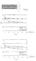
- the cycle characteristic of the discharging capacity up to 20 cycles is shown in FIG. 3.
- the initial discharging capacity of Example 4 was slightly lower than that of Comparative Example 4 but Example 4 exhibited little deterioration in the cycle characteristic and maintained 98% of the initial capacity after 20 cycles.
- Example 4 The same battery as that of Example 4 was produced and the charging-discharging cycle test was conducted at 25°C and at constant current of 0.1mA/cm 2 and rapid charging-discharging of 1 and 3mA/cm 2 with charging finish voltage of 3.0V and discharging finish voltage of 2.2V.
- the positive electrode layer and the negative electrode layer were attached to both surfaces of the solid electrolyte (separator) in the form of a sheet and the assembly was passed through a roll press to produce a battery in the form of a sheet having thickness of 210 ⁇ m.
- the battery was cut into a sheet having a size of 40 ⁇ 50mm and lead wires were connected to the positive electrode collector and the negative electrode collector.
- the charging -discharging cycle test was conducted under the same conditions as in Example 4. The initial discharging capacity and the discharging capacity after 20 cycles of Example 5 and Comparative Example 5 are shown in Table 3.
- Example 5 Comparative Example 5 Initial capacity (mAh) Capacity after 20 cycles(mAh) Initial capacity (mAh) Capacity after 20 cycles(mAh) Charging/ discharging density 0.1mA/cm 2 32.0 31.3 30.8 29.0 1mA/cm 2 32.0 31.1 25.3 23.1 3mA/cm 2 31.5 30.3 20.4 16.5
- Example 5 There was not much difference between the batteries of Example 5 and Comparative Example 5 at the charging-discharging rate of 0.1mA/cm 2 but, as the charging-discharging density was raised to perform rapid charging-discharging, reduction in the capacity was clearly observed in Comparative Example 5. This reduction was caused by increase in resistance to moving of ion in the interface between the positive electrode and the solid electrolyte and the interface between the solid electrolyte and the negative electrode. In Example 5 in which the solid electrolyte was formed directly on the electrode, a battery capable of functioning adequately at a large output was obtained.
- the lithium ion secondary battery having the thin film solid electrolyte of the present invention has a high output and excellent charging-discharging cycle characteristic. Further, since the battery of the invention does not contain an organic electrolytic solution a lithium ion secondary battery which is safer and more durable than the prior art batteries can be realized.
- the lithium ion secondary battery having the thin film solid electrolyte of the present invention has realized excellent contact in the interface between the positive or negative electrode and the electrolyte by forming the solid electrolyte directly on the electrode whereby a battery having a high capacity and a large output can be provided.
Abstract
Description
- This invention relates to a lithium ion secondary battery employing a thin film solid electrolyte and a method for manufacturing the same.
- In the past, a non-aqueous electrolytic solution was generally used as an electrolytic solution for a lithium ion secondary battery. A lithium ion secondary battery employing a polymer electrolyte made of polymer as disclosed by Japanese Patent Application Laid-open Publication No. 2000-067917 has recently attracted more attention of the industry than such electrolytic solution employing liquid.
- The lithium ion secondary battery employing a polymer electrolyte holds a liquid electrolytic solution in the polymer electrolyte and, therefore, has the advantage that there is little possibility of leakage of the liquid, that there is little possibility of corrosion, that short-circuiting between electrodes caused by precipitation of lithium in the form of dendrite can be prevented and that assembly of the battery is easy because the structure of the battery is very simple.
- Since lithium ion conductivity of such polymer electrolyte is lower than an electrolyte containing only an electrolytic solution, there has occurred a practice to reduce thickness of the polymer electrolyte. There, however, has arisen a problem in such polymer electrolyte whose thickness is reduced that, since its mechanical strength is reduced, the polymer electrolyte tends to be broken or give rise to a hole during production of the battery resulting in short-circuiting between the positive electrode and the negative electrode. The gel polymer electrolyte is reported to have thickness in the order of 30 µ m to 80 µm.
- For improving the mechanical strength, there is a proposal in Japanese Patent Application Laid-open Publication No. 2001-015164 for a compound electrolyte containing lithium ion conductive glass-ceramic powder. This proposal however has not realized a thin film electrolyte having thickness of 20 µm or below.
- There are also many proposals, e.g., in Japanese Patent Application Laid-open Publication No. Hei 07-326373, for a solid electrolyte battery which does not employ an electrolytic solution at all. Since a lithium ion secondary battery employing a solid electrolyte does not require an organic electrolytic solution as in the prior art batteries, there is no risk of leakage of solution and combustion and, therefore, a highly safe battery can be provided. In the prior art battery employing an organic electrolytic solution, the positive electrode and the negative electrode contact each other by means of the organic electrolytic solution through the solid electrolyte and, therefore, resistance in moving of ions in the interface does not cause a serious problem. If, however, all of the positive electrode, negative electrode and electrolyte composing the battery are made of solid, contact in the interface between the positive electrode and the electrolyte and contact in the interface between the negative electrode and the electrolyte become contacts between solids which include point contacts in some parts of the interfaces and thereby produce a large interface resistance as compared with the prior art batteries employing the electrolytic solution. Hence, the solid electrolyte battery has a large impedance in the interfaces which tends to cause polarization and thereby restrict moving of lithium ion in the interfaces with the result that it is difficult to realize a battery having a large capacity and a large output by such solid electrolyte battery.
- It is, therefore, an object of the present invention to provide a lithium ion secondary battery which has solved the above problems and has a thin electrolyte and thereby has small resistance notwithstanding that a solid electrolyte is employed and, therefore, has a high battery capacity and a high output and an excellent charging- discharging characteristic and thereby ensures a stabilized use over a long period of time.
- As a result of detailed studies and experiments, the inventor of the present invention has found, which has led to the present invention, that an inorganic substance having a certain crystal has a high lithium ion conductivity and its lithium ion transport number is 1 and that, by employing this substance as a solid electrolyte in the form of a thin film in a lithium ion secondary battery, a battery of a high performance can be realized.
- A lithium ion secondary battery according to the invention comprises a positive electrode, a negative electrode and a solid electrolyte, said solid electrolyte being made in the form of a thin film comprising a lithium ion conductive inorganic substance.
- The thin film solid electrolyte should preferably comprise an inorganic substance of a high lithium ion conductivity and, more preferably, a lithium ion conductive crystal, glass or glass-ceramics. In the thin film solid electrolyte used in the lithium ion secondary battery of the invention, the thinner the thin film solid electrolyte, the shorter is moving distance of lithium ion and, therefore, the higher is the output of the battery. In the lithium ion secondary battery, therefore, the thin film solid electrolyte should preferably have thickness of 20 µm or below and, more preferably, 10 µm or below and, most preferably, 5 µm or below.
- Mobility of lithium ion during charging and discharging in the lithium ion secondary battery of the present invention depends upon lithium ion conductivity and lithium ion transport number of the solid electrolyte. Accordingly, in the lithium ion secondary battery- of the invention, the thin film solid electrolyte should preferably have lithium ion conductivity of 10-5Scm-1 or over.
- In the accompanying drawings,
- FIG. 1 is a schematic sectional view showing an internal structure of the lithium ion secondary battery of the present invention;
- FIG. 2 is a graph showing change in the discharging capacity accompanying the charging-discharging cycles of the lithium ion secondary battery s of Example 1 and Comparative Example 1; and
- FIG. 3 is a graph showing change in the discharging capacity accompanying the charging-discharging cycles of the lithium ion secondary batteries of Example 4 and Comparative Example 4
-
- In a preferred embodiment of the invention, the thin film solid electrolyte should preferably comprise the inorganic substance in an amount of 40 weight % or over. The inorganic substance should preferably be an ion conductive crystal, glass or glass-ceramic. The inorganic substance should preferably be powder of the inorganic substance. The inorganic substance powder in the thin film solid electrolyte should preferably have an average particle diameter of 1.0 µm or below, more preferably 0.5 µm or below and, most preferably, 0.3 µm or below.
- In the lithium ion secondary battery of the invention, the thin film solid electrolyte may comprise a lithium ion conductive inorganic substance powder in a polymer medium. The thin film solid electrolyte should preferably comprise a lithium inorganic salt and lithium ion conductive glass-ceramic powder.
- In the lithium ion secondary battery of the invention, the thin film solid electrolyte may be formed by direct coating on an electrode material or materials for the positive electrode and/or the negative electrode.
- The method for manufacturing a lithium ion secondary battery having a thin film solid electrolyte comprising a lithium ion conductive inorganic substance according to the invention comprises a step of forming the thin film solid electrolyte by coating the lithium ion conductive inorganic substance directly on an electrode material or materials for the positive and/or negative electrode.
- As described above, the thinner the solid electrolyte, the less is resistance and the shorter is moving distance of ion and, therefore, the higher is the output of the battery. However, in a case where the solid electrolyte is produced independently and separately from the other components of the battery, there is limitation in making the solid electrolyte thin for reasons of strength and handling as well as the manufacturing process. According to the method for manufacturing a lithium ion secondary battery of the invention, the solid electrolyte is formed directly on an electrode material or materials for the positive electrode and/or the negative electrode and, therefore, there is no problem caused by handling an independent solid electrolyte and hence the solid electrolyte can be made even thinner.
- The thin film solid electrolyte may be formed by preparing slurry comprising lithium ion conductive crystal, glass or glass-ceramic as the inorganic substance, and coating the slurry directly on the electrode material or materials for the positive and/or negative electrode.
- For coating the slurry directly on the electrode material or materials for the positive electrode and/or the negative electrode, dipping, spin coating or tape casting may be employed or printing technique such as ink jetting or screen printing may be employed. As the slurry, lithium ion conductive powder of an inorganic substance may be dispersed with a binder in a medium. Preferable inorganic substances are a crystal, glass and glass-ceramic. The thin film solid electrolyte should preferably comprise an inorganic substance in an amount of 40 weight % or over.
- The lithium ion conductive powder used in the present invention should preferably have a high lithium ion conductivity and, more preferably, a chemically stable glass-ceramic. A specific example of the powder of the chemically stable glass-ceramic is powder of glass-ceramic which is produced by heat-treating a Li2O-Al2O3-TiO2-SiO2-P2O5 mother glass for crystallization and contains Li1+x+yAlxTi2-xSiyP3-yO12 (0≦x≦1, 0≦y≦1) as a predominant crystal phase.
- For binding particles of crystal, glass or glass-ceramic powder to one another and also binding these particles to the electrodes which constitute substrates, an organic polymer material may be employed as the binder. Specifically, a polymer material such as polyethylene oxide, polyethylene, polypropyrene, polyolefin, fluorine resin such as polytetrafluoroethylene, polychlorotrifluoroethylene and polyvinylydene fluoride, polyamides, polyesters and polyacrylates, or a polymer material comprising such polymer as a constituent element may be used. A binder having lithium ion conductivity or a polymer imparted with lithium ion conductivity by adding lithium salt or the like material is more preferably because such binder improves ion conductivity of the compound electrolyte. As the medium, an organic medium in which the above described polymer material is dissolved or dispersed may be used.
- In the lithium ion secondary battery of the invention, the thin film solid electrolyte may also be formed by coating a lithium ion conductive inorganic substance directly on an electrode material. For the direct coating known methods for making a thin film such as sputtering, laser abrasion and plasma spraying may be used. In this case, a lithium ion conductive crystal or glass or a compound material including such lithium ion conductive crystal or glass may be used as a target for forming a thin film directly on an electrode material.
- As a target material, the above described chemically stable and highly lithium ion conductive glass-ceramic may preferably be employed. In making a thin film, this glass-ceramic sometimes becomes amorphous but, in this case, there will be no problem if the above described predominant crystal phase is caused to precipitate by crystallizing the amorphous glass by heat-treating. Similarly, the mother glass from which this glass-ceramic is obtained may be employed as the target. In this case also, the above described predominant crystal phase can be produced by the crystallizing process after the film has been formed. A target made of a compound material can be obtained by mixing an inorganic binder to powder of a lithium ion conductive crystal, glass or glass-ceramic and sintering the mixture. The glass-ceramic powder should preferably have lithium ion conductivity and, more preferably, should contain Li1+x+yAlxTi2-xSiyP3-yO12 as a predominant crystal phase. This glass-ceramic powder should preferably have an average particle diameter of 5 µm or below and, more preferably, 3 µ m or below. The inorganic binder used should preferably be a crystal or glass which is an inorganic oxide having a low melting point. The amount of this inorganic binder should preferably be 20 weight % or below.
- In the lithium ion secondary battery using the thin film solid electrolyte of the invention, the positive electrode may be made by forming a material containing a transition metal oxide as a positive electrode active material on an aluminum foil used as a positive electrode collector. As the positive electrode active material, a transition metal compound capable of absorbing and storing and discharging lithium may be used. For example, an oxide or oxides containing at least one transition metal selected from manganese, cobalt, iron, nickel, vanadium, niobium, molybdenum, titanium etc. may be used. In a case where a material which does not contain lithium is used as a negative electrode active material, a transition metal oxide containing lithium may preferably be used.
- In the lithium ion secondary battery using the thin film solid electrolyte of the invention, the lithium ion conductive inorganic substance may preferably be used not only for the thin film solid electrolyte but also in the positive electrode as an ion conductive additive. As the lithium ion conductive inorganic substance used for the positive electrode, glass-ceramic powder containing Li1+x+yAlxTi2-xSiyP3-yO12 as a predominant crystal phase as is used in the thin film solid electrolyte may preferably be used. This glass-ceramic powder should preferably have an average particle diameter of 5 µm or below and, more preferably, 3 µm or below.
- In the lithium ion secondary battery using the thin film solid electrolyte of the invention, an electric conductive additive and/or a binder may preferably be used in the positive electrode. As the electric conductive additive, acetylene black may preferably be used and, as the binder, polyvinylidene fluoride PVdF may be preferably be used.
- In the lithium ion secondary battery of the invention, the negative electrode may be made by forming a material containing a negative electrode active material on a copper foil used as a negative electrode collector. As the negative electrode active material, a metal or alloy capable of absorbing and storing and discharging lithium such as metal lithium, lithium-aluminum alloy and lithium-indium alloy, transition metal oxides such as titanium and vanadium, and carbon materials such as graphite, active carbon and mesophase pitch carbon fiber may be used.
- In the lithium ion secondary battery of the invention, the lithium ion conductive inorganic substance may preferably be used not only for the thin film solid electrolyte but also in the negative electrode as an ion conductive additive. As the lithium ion conductive inorganic substance used for the negative electrode, glass-ceramic powder containing Li1+x+yAlxTi2-xSiyP3-yO12 as a predominant crystal phase as is used in the thin film solid electrolyte may preferably be used. The negative electrode may be produced by mixing a negative electrode active material with an ion conductive additive and a binder in acetone solvent and coating the mixture on the negative electrode collector. As the negative electrode active material, commercially available graphite powder may be used.
- In the following description, the thin film solid electrolyte and the lithium ion secondary battery using it will be described with reference to specific examples and advantages of the lithium ion secondary battery having the thin film solid electrolyte of the invention will be described with reference to comparative examples. It should be noted that the present invention is not limited by the following examples but various modifications can be made within the scope and spirit of the invention.
- As the positive electrode active material, commercially available lithium cobalt oxide (LiCoO2) was used. This positive electrode active material, acetylene black used as an electric conductive additive, glass-ceramic powder containing Li1+x+yAlxTi2-xSiyP3-yO12 as a predominant crystal phase used as an ion conductive additive and polyvinylidene fluoride PVdF used as a binder were mixed together in acetone solvent and this mixture was coated on a positive electrode collector made of an aluminum sheet having thickness of 10 µm to thickness of about 50 µm and was dried under temperature of 100°C to prepare a positive electrode in the form of a sheet. As the glass-ceramic powder, glass-ceramic powder having an average particle diameter of 1.0 µm (average in volume) and a maximum particle diameter of 8 µm was used. The particle diameter was measured using a laser diffraction/dispersion particle distribution measuring device.
- As the negative electrode active material, commercially available graphite powder was used. This negative electrode active material, glass-ceramic powder used as an ion-conductive additive which was the same material used for the positive electrode, i.e.; containing Li1+x+yAlxTi2-xSiyP3-yO12 as a predominant crystal phase and having an average particle diameter of 1.0 µm and a maximum particle diameter of 8 µ m, and polyvinylidene fluoride PVdF used as a binder were mixed together in acetone solvent and this mixture was coated on a negative electrode collector made of a copper sheet having thickness of 10 µm up to thickness of about 50 µm and was used under temperature of 100°C to prepare a negative electrode in the form or a sheet.
- Glass-ceramic powder containing Li1+x+yAlxTi2-xSiyP3-yO12 as a predominant crystal phase and having an average particle diameter of 0.15 µ m and a maximum particle diameter of 0.3 µm and polyethyleneoxide added with LiBF4 as a lithium salt were mixed uniformly in acetone solvent. This mixture was coated respectively on the active material side of the positive electrode and the active material side of the negative electrode and then acetone used as the solvent was dried and thereby removed whereby a thin film solid electrolyte layer was formed directly on the electrode materials for the positive and negative electrodes. The positive and negative electrodes were passed through a roll press with the coated sides of these electrodes being in contact with each other and was cut into a sheet having a size of 40 X 50mm. Thus, a lithium ion secondary battery shown in FIG. 1 having a thin film solid electrolyte 3 formed between a positive electrode 2 and a negative electrode 4 was produced. The total thickness of this battery was 110 µm and the thickness of the thin film solid electrolyte in the battery was 3 µm.
- Lead wires were connected to a
positive electrode collector 1 and a negative electrode collector 4 and the charging- discharging cycle test was conducted at 25°C with charging finish voltage of 4.2V and discharging finish voltage of 3.5V The cycle characteristic of the discharging capacity up to 20 cycles is shown in FIG. 2. Initial discharging capacity of Example 1 was 36.2mAh and discharging capacity after 20 cycles was 34.1mAh, thus maintaining more than 96% of the initial discharging capacity. - The same battery as the battery of Example 1 was produced except that glass-ceramic powder was not used but polyethyleneoxide added with LiBF4 only was used for the thin film solid electrolyte. The charging-discharging cycle test was conducted under the same conditions as in Example 1. The cycle characteristic of the discharging capacity up to 20 cycles is shown in FIG. 2.
- Commercially available lithium cobalt oxide (LiCoO2) was used as the positive electrode active material. This positive electrode active material and the same electric conductive additive, ion conductive additive and binder as used in Example 1 were mixed in acetone solvent. This mixture was coated on a positive electrode collector made of an aluminum sheet having thickness of 10 µm to thickness of about 50 µm to form a positive electrode layer. Immediately thereafter, the same mixture of glass-ceramic powder and polyethyleneoxide added with a lithium salt as used in preparation of the thin film solid electrolyte in Example 1 was coated thinly on the positive electrode layer to form an electrolyte layer. Then, the same mixture as used in preparation of the negative electrode in Example 1 was coated on the electrolyte layer to thickness of about 50 µm. A copper sheet which constituted the negative electrode collector was attached to the coated side of the negative electrode and, after drying under 100°C, the assembly was passed through a roll press and was cut into a sheet having a size of 40 × 50mm. Thus, a lithium ion secondary battery shown in FIG. 1 having a thin film solid electrolyte 3 formed between a positive electrode 2 and a negative electrode 4 was produced. The total thickness of this battery was 100µm and the thickness of the thin film solid electrolyte in the battery was about 2 µm. Since no drying process was inserted in the coating of the positive electrode, the electrolyte and the negative electrode, the positive electrode layer and the solid electrolyte layer existed in a mixed state in some portions of the interface between them and the solid electrolyte layer and the negative electrode existed in a mixed state in some portions of the interface between them.
- Lead wires were connected to a
positive electrode collector 1 and a negative electrode collector 4 and the charging-discharging cycle test was conducted at 25°C and a constant current of 0.1mA/cm2 and with charging finish voltage of 4.2V and discharging finish voltage of 3.5V The charging-discharging cycle test was also conducted at constant current of 1mAh/cm2. - The same battery as the battery of Example 2 was produced except that glass-ceramic powder was not used for the thin film solid electrolyte. The charging-discharging cycle test was conducted under the same condition as in Example 2. Comparison between Example 2 and Comparative Example 2 of the initial discharging capacity of charging and discharging densities of 0.1mA/cm2 and 1mA/cm2 and the discharging capacity after 20 cycles are shown in Table 1.
Example 2 Comparative Example 2 0.1mAcm2 1mAcm2 0.1mAcm2 1mAcm2 Initial discharging capacity (mAh) 39.2 38.8 35.0 32.2 Discharging capacity after 20 cycles (mAh) 36.3 35.1 31.2 26.5 - As will be understood from Table 1, in the battery of Example 2, deterioration of the discharging capacity with lapse of the cycle and deterioration of the discharging capacity due to rapid charging and discharging were both mitigated compared with Comparative Example 2.
- The same glass-ceramic powder containing Li1+x+yAlxTi2-xSiyP3-yO12 as a predominant crystal phase and having an average particle diameter of 1.0 µ m as used in preparation of the positive electrode in Example 1 was pressed and formed to a disk by using lithium phosphate Li3PO4 as the inorganic binder and thereafter the disk was sintered to provide a target material. A sputtering target having a diameter of 100mm and thickness of 1mm was obtained by grinding and polishing the outer periphery and both surfaces of the target material.
- A thin film was formed on a lithium-aluminum alloy foil having a diameter of 20mm and thickness of 20 µm by using an RF magnetron sputtering device. The solid electrolyte obtained had thickness of 0.1 µm. Then, a LiCoO2 positive electrode film was formed on thin film solid electrolyte. The positive electrode film obtained had thickness of 2 µm. An aluminum film was formed as a positive electrode collector on this positive electrode film to thickness of 0.1 µm. Since the solid electrolyte and the positive electrode film became amorphous, heat treatment at 550°C was applied and a thin film battery having thickness of about 22 µm was obtained. A disk having a diameter of 18mm was stamped out from this battery and put in a coin battery having a diameter of 20mm to assemble a coin type battery.
- The charging discharging cycle test was conducted at -20°C, 25°C and 80°C and a constant current of 1mAh/cm2 and with charging finish voltage of 3.5V and discharging finish voltage of 2.5V Also, the assembled coin type battery was mounted on a circuit substrate by reflow soldering at 250°C and a similar cycle test was conducted at 25°C.
- An electrolyte was prepared by impregnating non-woven cloth with a conventional electrolytic solution and a battery was produced using this electrolyte. The same negative electrode made of lithium-aluminum alloy as in Example 1 was used and a positive electrode was prepared by forming a film of LiCoO2 on an aluminum foil having thickness of 10 µm by a sputtering device in the same manner as in Example 1. The positive electrode and the negative electrode were attached to each other through a separator made of non-woven cloth having thickness of 26 µm and the separator was impregnated with propylene carbonate added with LiN(C2F5SO2)2 as a lithium salt whereby a thin film battery having thickness of about 58 µm was produced. In all other respects, the same process as in Example 3 was followed to produce a coin type battery. The charging-discharging test was conducted under the same conditions as in Example 3.
- Comparison between Example 3 and Comparative Example 3 of initial discharging capacity discharging capacity after 300 cycles, initial discharging capacity and discharging capacity after 300 cycles after reflow soldering at different temperatures are shown in Table 2.
Example 3 Comparative Example 3 Initial capacity (mAh) Capacity after 300 cycles(mAh) Initial capacity (mAh) Capacity after 300 cydes(mAh) - 20°C 0.12 0.11 0.05 0.02 25°C 0.22 0.20 0.22 0.16 80°C 0.24 0.19 0.22 0.12 25°C(reflow soldering) 0.21 0.18 bursting - From Table 2, it will be understood that the battery of Example 3 had excellent cycle characteristic at the respective temperature and, even at -25°C, maintained about 50% of the capacity at the room temperature. The battery of Comparative Example 3 was burst by reflow soldering whereas the battery of Example 3 caused little change in the capacity by reflow soldering.
- A positive electrode layer and a think film electrolyte layer were formed on a positive electrode collector made of aluminum in the same manner as in Example 1 except that LiMn2O4 was used as the positive electrode active material.
- As the negative electrode active material, Li4Ti5O12 was used. This negative electrode active material, glass-ceramic powder used as an ion conductive additive and polyvinylidene fluoride PVdF used as a binder were mixed together in acetone solvent and this mixture was coated on a negative electrode collector made of a copper sheet having thickness of 10 µm to thickness of about 50 µm to prepare a negative electrode layer on the negative electrode collector. Immediately thereafter, the same mixture of glass-ceramic powder and polyethyleneoxide added with a lithium salt as used for preparation of the thin film solid electrolyte in Example 1 was coated thinly on the negative electrode layer to form a thin film electrolyte layer.
- The positive electrode and the negative electrode were attached to each other on their electrolyte side and were passed through a roll press at 100°C and dried. The positive electrode layer had thickness of 60 µm, the thin film solid electrolyte layer had thickness of 3 µm, the negative electrode layer had thickness of 100 µm and the total thickness was about 180 µm. The assembly was cut into a sheet having a size of 40 × 50mm and lead wires were connected to the positive electrode collector and the negative electrode collector. Charging-discharging cycle test was conducted at 25 °C at a constant current of 0.1mA/cm2 and with charging finish voltage of 3.0V and discharging finish voltage of 2.2V.
- The same battery as the battery of Example 4 was produced except that glass-ceramic powder was not used for the electrolyte layers of the positive and negative electrodes. The charging-discharging cycle test was conducted under the same conditions as in Example 4. The cycle characteristic of the discharging capacity up to 20 cycles is shown in FIG. 3. The initial discharging capacity of Example 4 was slightly lower than that of Comparative Example 4 but Example 4 exhibited little deterioration in the cycle characteristic and maintained 98% of the initial capacity after 20 cycles.
- The same battery as that of Example 4 was produced and the charging-discharging cycle test was conducted at 25°C and at constant current of 0.1mA/cm2 and rapid charging-discharging of 1 and 3mA/cm2 with charging finish voltage of 3.0V and discharging finish voltage of 2.2V.
- Glass-ceramic powder and polyethyleneoxide added with LiBF4 as a lithium salt was uniformly mixed in acetone solvent and this mixture was coated on a cast sheet to thickness of 50 µm, dried and passed through a roll press to produce a solid electrolyte in the form of a sheet having thickness of 30 µm. In the same manner as in Example 4, a positive electrode layer was formed on a positive electrode collector made of aluminum and a negative electrode layer was formed on a negative electrode collector made of a copper sheet. The positive electrode layer and the negative electrode layer were attached to both surfaces of the solid electrolyte (separator) in the form of a sheet and the assembly was passed through a roll press to produce a battery in the form of a sheet having thickness of 210 µm. The battery was cut into a sheet having a size of 40 × 50mm and lead wires were connected to the positive electrode collector and the negative electrode collector. The charging -discharging cycle test was conducted under the same conditions as in Example 4. The initial discharging capacity and the discharging capacity after 20 cycles of Example 5 and Comparative Example 5 are shown in Table 3.
Example 5 Comparative Example 5 Initial capacity (mAh) Capacity after 20 cycles(mAh) Initial capacity (mAh) Capacity after 20 cycles(mAh) Charging/ discharging density 0.1mA/cm2 32.0 31.3 30.8 29.0 1mA/cm2 32.0 31.1 25.3 23.1 3mA/cm2 31.5 30.3 20.4 16.5 - There was not much difference between the batteries of Example 5 and Comparative Example 5 at the charging-discharging rate of 0.1mA/cm2 but, as the charging-discharging density was raised to perform rapid charging-discharging, reduction in the capacity was clearly observed in Comparative Example 5. This reduction was caused by increase in resistance to moving of ion in the interface between the positive electrode and the solid electrolyte and the interface between the solid electrolyte and the negative electrode. In Example 5 in which the solid electrolyte was formed directly on the electrode, a battery capable of functioning adequately at a large output was obtained.
- As described above, the lithium ion secondary battery having the thin film solid electrolyte of the present invention has a high output and excellent charging-discharging cycle characteristic. Further, since the battery of the invention does not contain an organic electrolytic solution a lithium ion secondary battery which is safer and more durable than the prior art batteries can be realized.
- Further, in comparison with the prior art secondary battery having a solid electrolyte which has large electrochemical resistance in the interface between the positive electrode and the electrolyte or the interface between the electrolyte and the negative electrode, the lithium ion secondary battery having the thin film solid electrolyte of the present invention has realized excellent contact in the interface between the positive or negative electrode and the electrolyte by forming the solid electrolyte directly on the electrode whereby a battery having a high capacity and a large output can be provided.
- In the prior art lithium ion secondary battery, there was a problem that, if the electrolyte is extremely thin, short-circuiting due to internal short-circuiting takes place when external stress is applied to the battery or the battery is bent. In the lithium ion secondary battery having the thin film solid electrolyte of the invention, a relatively large quantity of inorganic substance such as glass-ceramic powder is present in the solid electrolyte and, therefore, internal short-circuiting due to external stress does not take place. Besides, in a case where the thin film solid electrolyte is formed by sputtering, the entire solid electrolyte can be made of glass-ceramic and, in this case, possibility of short-circuiting can be totally eliminated.
Claims (20)
- A lithium ion secondary battery comprising a positive electrode, a negative electrode and a solid electrolyte, said solid electrolyte being made in the form of a thin film comprising a lithium ion conductive inorganic substance.
- A lithium ion secondary battery as defined in claim 1 wherein said thin film solid electrolyte has thickness of 20 µm or below.
- A lithium ion secondary battery as defined in claim 1 or 2 wherein said thin film solid electrolyte is formed directly on an electrode material or materials for the positive electrode and/or the negative electrode.
- A lithium ion secondary battery as defined in any of claims 1 - 3 wherein said thin film solid electrolyte has lithium ion conductivity of 10-5Scm-1 or over.
- A lithium ion secondary battery as defined in any of claims 1 - 4 wherein said thin film solid electrolyte comprises the inorganic substance in an amount of 40 weight % or over.
- A lithium ion secondary battery as defined in any of claims 1 - 5 wherein said inorganic substance is a lithium ion conductive crystal.
- A lithium ion secondary battery as defined in any of claims 1 - 5 wherein said inorganic substance is a lithium ion conductive glass.
- A lithium ion secondary battery as defined in any of claims 1 - 5 wherein said inorganic substance is a lithium ion conductive glass-ceramic.
- A lithium ion secondary battery as defined in any of claims 1 - 8 wherein said inorganic substance is powder of the inorganic substance.
- A lithium ion secondary battery as defined in claim 9 wherein said inorganic substance powder is powder of a lithium ion conductive glass-ceramic.
- A lithium ion secondary battery as defined in claim 9 or 10 wherein an average grain diameter of the inorganic substance powder is 1.0 µm or below.
- A lithium ion secondary battery as defined in any of claims 9 - 11 wherein said thin film solid electrolyte comprises a lithium ion conductive inorganic substance powder in a polymer medium.
- A lithium ion secondary battery as defined in any of claims 9 - 12 wherein said thin film solid electrolyte comprises a lithium inorganic salt and lithium ion conductive glass-ceramic powder in a polymer medium.
- A lithium ion secondary battery as defined in any of claims 3 - 13 wherein said thin film solid electrolyte is formed by direct coating on an electrode material or materials for the positive electrode and/or the negative electrode.
- A lithium ion secondary battery as defined in any of claims 3 - 14 wherein said thin film solid electrolyte is formed by crystallizing an amorphous layer which is formed by direct coating on an electrode material or materials for the positive electrode and/or the negative electrode.
- A lithium ion secondary battery as defined in any of claims 1 - 15 comprising a positive electrode, a negative electrode and a solid electrolyte wherein said positive and/or negative electrode comprises lithium ion conductive inorganic substance powder.
- A lithium ion secondary battery as defined in claim 16 wherein said inorganic substance powder in the positive and/or negative electrode has an average grain diameter of 3 µm or below.
- A method for manufacturing a lithium ion secondary battery having a thin film solid electrolyte comprising a lithium ion conductive inorganic substance comprising a step of forming the thin film solid electrolyte by coating the lithium ion conductive inorganic substance directly on an electrode material or materials for the positive and/or negative electrode.
- A method for manufacturing a lithium ion secondary battery as defined in claim 18 comprising a step of preparing slurry comprising the lithium ion conductive inorganic substance, and a step of forming the thin film solid electrolyte by coating the slurry directly on the electrode material or materials for the positive and/or negative electrode.
- A method for manufacturing a lithium ion secondary battery as defined in claim 18 comprising a step of coating the lithium ion conductive inorganic substance directly on the electrode material or materials for the positive and/or negative electrode to form an amorphous layer, and a step of forming the thin film solid electrolyte by crystallizing the amorphous layer.
Applications Claiming Priority (2)
| Application Number | Priority Date | Filing Date | Title |
|---|---|---|---|
| JP2002348532A JP4777593B2 (en) | 2002-11-29 | 2002-11-29 | Method for producing lithium ion secondary battery |
| JP2002348532 | 2002-11-29 |
Publications (2)
| Publication Number | Publication Date |
|---|---|
| EP1424743A1 true EP1424743A1 (en) | 2004-06-02 |
| EP1424743B1 EP1424743B1 (en) | 2006-11-22 |
Family
ID=32290503
Family Applications (1)
| Application Number | Title | Priority Date | Filing Date |
|---|---|---|---|
| EP03027366A Expired - Lifetime EP1424743B1 (en) | 2002-11-29 | 2003-11-27 | Lithium ion secondary battery with Li ion conductive inorganic solid electrolyte and a method for manufacturing the same |
Country Status (10)
| Country | Link |
|---|---|
| US (3) | US20040106046A1 (en) |
| EP (1) | EP1424743B1 (en) |
| JP (1) | JP4777593B2 (en) |
| KR (1) | KR100580442B1 (en) |
| CN (1) | CN1505198B (en) |
| AT (1) | ATE346392T1 (en) |
| CA (2) | CA2451181C (en) |
| DE (1) | DE60309815T2 (en) |
| HK (1) | HK1065649A1 (en) |
| TW (1) | TWI265652B (en) |
Cited By (16)
| Publication number | Priority date | Publication date | Assignee | Title |
|---|---|---|---|---|
| WO2006019064A2 (en) * | 2004-08-17 | 2006-02-23 | Kabushiki Kaisha Ohara | Lithium ion secondary battery and a solid electrolyte thereof |
| WO2006059794A2 (en) * | 2004-12-02 | 2006-06-08 | Kabushiki Kaisha Ohara | All solid lithium ion secondary battery and a solid electrolyte therefor |
| EP1775789A3 (en) * | 2005-10-13 | 2008-03-12 | Ohara Inc. | Lithium ion conductive solid electrolyte and method for manufacturing the same |
| EP1760819A3 (en) * | 2005-08-31 | 2008-03-26 | Ohara Inc. | Lithium ion secondary battery and solid electrolyte therefor |
| EP2086039A1 (en) * | 2008-01-31 | 2009-08-05 | Ohara Inc. | Lithium ion secondary battery and manufacture thereof |
| EP2086046A1 (en) * | 2008-01-31 | 2009-08-05 | Ohara Inc. | Manufacture of lithium ion secondary battery |
| WO2011066518A1 (en) * | 2009-11-30 | 2011-06-03 | Oc Oerlikon Balzers Ag | Lithium ion battery and method for manufacturing of such battery |
| US20110300451A1 (en) * | 2006-03-30 | 2011-12-08 | Ohara Inc. | Lithium ion conductive solid electrolyte and production process thereof |
| EP2394321A2 (en) * | 2009-02-03 | 2011-12-14 | Ceramatec, Inc | Electrochemical cell comprising ionically conductive ceramic membrane and porous multiphase electrode |
| WO2011161019A1 (en) * | 2010-06-24 | 2011-12-29 | Basf Se | Cathode for lithium ion rechargeable batteries |
| WO2012076950A1 (en) * | 2010-12-05 | 2012-06-14 | Ramot At Tel-Aviv University Ltd. | Electrophoretic deposition of thin film batteries |
| WO2013064779A1 (en) | 2011-11-02 | 2013-05-10 | Fabien Gaben | Method for manufacturing all-solid-state thin-film batteries |
| US9580320B2 (en) * | 2005-10-13 | 2017-02-28 | Ohara Inc. | Lithium ion conductive solid electrolyte and method for manufacturing the same |
| WO2018006016A1 (en) | 2016-06-30 | 2018-01-04 | Wildcat Discovery Technologies, Inc. | Solid electrolyte compositions |
| WO2019215411A1 (en) | 2018-05-07 | 2019-11-14 | I-Ten | Porous ceramic for electrolytes used in thin-film electrochemical devices |
| WO2019215410A1 (en) | 2018-05-07 | 2019-11-14 | I-Ten | Solid electroyte for electrochemical devices |
Families Citing this family (91)
| Publication number | Priority date | Publication date | Assignee | Title |
|---|---|---|---|---|
| US9793523B2 (en) | 2002-08-09 | 2017-10-17 | Sapurast Research Llc | Electrochemical apparatus with barrier layer protected substrate |
| US8236443B2 (en) | 2002-08-09 | 2012-08-07 | Infinite Power Solutions, Inc. | Metal film encapsulation |
| US8021778B2 (en) | 2002-08-09 | 2011-09-20 | Infinite Power Solutions, Inc. | Electrochemical apparatus with barrier layer protected substrate |
| US8431264B2 (en) | 2002-08-09 | 2013-04-30 | Infinite Power Solutions, Inc. | Hybrid thin-film battery |
| US8394522B2 (en) | 2002-08-09 | 2013-03-12 | Infinite Power Solutions, Inc. | Robust metal film encapsulation |
| US20070264564A1 (en) | 2006-03-16 | 2007-11-15 | Infinite Power Solutions, Inc. | Thin film battery on an integrated circuit or circuit board and method thereof |
| US8445130B2 (en) | 2002-08-09 | 2013-05-21 | Infinite Power Solutions, Inc. | Hybrid thin-film battery |
| US8404376B2 (en) | 2002-08-09 | 2013-03-26 | Infinite Power Solutions, Inc. | Metal film encapsulation |
| US8728285B2 (en) | 2003-05-23 | 2014-05-20 | Demaray, Llc | Transparent conductive oxides |
| DE10328316A1 (en) | 2003-06-23 | 2005-01-20 | Grünenthal GmbH | Process for the preparation of dimethyl (3-aryl-butyl) -amine compounds as pharmaceutical active ingredients |
| WO2005112180A1 (en) * | 2004-05-14 | 2005-11-24 | Matsushita Electric Industrial Co., Ltd. | Lithium ion secondary battery |
| WO2006083300A2 (en) * | 2004-06-18 | 2006-08-10 | Massachusetts Institute Of Technology | Acceleration of charged particles using spatially and temporally shaped electromagnetic radiation |
| FR2872633B1 (en) * | 2004-07-02 | 2006-09-15 | Commissariat Energie Atomique | METHOD FOR CHARGING A LITHIUM-ION BATTERY WITH NEGATIVE ELECTRODE |
| BRPI0508130A (en) * | 2004-08-17 | 2007-07-17 | Lg Chemical Ltd | lithium secondary batteries with improved safety and performance |
| KR20070034104A (en) * | 2004-08-18 | 2007-03-27 | 자이단호징 덴료쿠추오켄큐쇼 | Polymer Solid Electrolyte Battery and Manufacturing Method of Positive Electrode Sheet Used in the Same |
| JP5197918B2 (en) * | 2004-12-02 | 2013-05-15 | 株式会社オハラ | All-solid lithium ion secondary battery and solid electrolyte |
| US7959769B2 (en) | 2004-12-08 | 2011-06-14 | Infinite Power Solutions, Inc. | Deposition of LiCoO2 |
| TWI331634B (en) | 2004-12-08 | 2010-10-11 | Infinite Power Solutions Inc | Deposition of licoo2 |
| KR100659851B1 (en) * | 2005-04-27 | 2006-12-19 | 삼성에스디아이 주식회사 | Lithium secondary battery |
| JP2007109636A (en) * | 2005-09-14 | 2007-04-26 | Nissan Motor Co Ltd | Electrode for battery |
| KR100686848B1 (en) * | 2005-10-11 | 2007-02-26 | 삼성에스디아이 주식회사 | Lithium rechargeable battery |
| JP4873925B2 (en) * | 2005-10-28 | 2012-02-08 | 株式会社オハラ | Lithium ion secondary battery and manufacturing method thereof |
| DE102005052588A1 (en) | 2005-11-02 | 2007-05-10 | Grünenthal GmbH | Process for the preparation of substituted dimethyl- (3-aryl-butyl) -amine compounds by means of homogeneous catalysis |
| JP5603011B2 (en) * | 2005-11-17 | 2014-10-08 | インフィニット パワー ソリューションズ, インコーポレイテッド | Electrochemical device and method of manufacturing the device |
| EP1997176B1 (en) * | 2006-03-16 | 2020-02-19 | Sapurast Research LLC | Metal film encapsulation |
| JP2007294429A (en) * | 2006-03-30 | 2007-11-08 | Ohara Inc | Lithium ion conductive solid electrolyte and its manufacturing method |
| JP4967470B2 (en) * | 2006-06-20 | 2012-07-04 | セイコーエプソン株式会社 | Droplet discharge device, liquid discharge method, and secondary battery manufacturing method |
| TWI496762B (en) | 2006-07-24 | 2015-08-21 | Process for the preparation of (1r,2r)-3-(3-dimethylamino-1-ethyl-2-methyl-propyl)-phenol | |
| EP2067163A4 (en) | 2006-09-29 | 2009-12-02 | Infinite Power Solutions Inc | Masking of and material constraint for depositing battery layers on flexible substrates |
| JP5110850B2 (en) * | 2006-10-31 | 2012-12-26 | 株式会社オハラ | Lithium ion conductive solid electrolyte and method for producing the same |
| US8197781B2 (en) | 2006-11-07 | 2012-06-12 | Infinite Power Solutions, Inc. | Sputtering target of Li3PO4 and method for producing same |
| JP2008135287A (en) * | 2006-11-28 | 2008-06-12 | Idemitsu Kosan Co Ltd | All-solid battery member and manufacturing method of the member, and all-solid battery |
| JP5157216B2 (en) * | 2007-03-29 | 2013-03-06 | Tdk株式会社 | Method for producing active material and active material |
| JP5211527B2 (en) * | 2007-03-29 | 2013-06-12 | Tdk株式会社 | All-solid lithium ion secondary battery and method for producing the same |
| JP5211526B2 (en) * | 2007-03-29 | 2013-06-12 | Tdk株式会社 | All-solid lithium ion secondary battery and method for producing the same |
| JP5304168B2 (en) * | 2007-11-12 | 2013-10-02 | 国立大学法人九州大学 | All solid battery |
| US8216722B2 (en) * | 2007-11-27 | 2012-07-10 | Ceramatec, Inc. | Solid electrolyte for alkali-metal-ion batteries |
| US8268488B2 (en) | 2007-12-21 | 2012-09-18 | Infinite Power Solutions, Inc. | Thin film electrolyte for thin film batteries |
| KR20150128817A (en) | 2007-12-21 | 2015-11-18 | 사푸라스트 리써치 엘엘씨 | Method for sputter targets for electrolyte films |
| JP5705549B2 (en) | 2008-01-11 | 2015-04-22 | インフィニット パワー ソリューションズ, インコーポレイテッド | Thin film encapsulation for thin film batteries and other devices |
| US10320033B2 (en) | 2008-01-30 | 2019-06-11 | Enlighten Innovations Inc. | Alkali metal ion battery using alkali metal conductive ceramic separator |
| CN101983469B (en) | 2008-04-02 | 2014-06-04 | 无穷动力解决方案股份有限公司 | Passive over/under voltage control and protection for energy storage devices associated with energy harvesting |
| JP2009295523A (en) * | 2008-06-09 | 2009-12-17 | Kazu Tomoyose | Solid electrolyte film |
| US9099758B2 (en) * | 2008-06-20 | 2015-08-04 | University Of Dayton | Lithium-air cell incorporating lithium aluminum germanium phosphate cathode |
| US9178255B2 (en) | 2008-06-20 | 2015-11-03 | University Of Dayton | Lithium-air cells incorporating solid electrolytes having enhanced ionic transport and catalytic activity |
| WO2010019577A1 (en) | 2008-08-11 | 2010-02-18 | Infinite Power Solutions, Inc. | Energy device with integral collector surface for electromagnetic energy harvesting and method thereof |
| JP5650646B2 (en) | 2008-09-12 | 2015-01-07 | インフィニット パワー ソリューションズ, インコーポレイテッド | Energy device with integral conductive surface for data communication via electromagnetic energy and method for data communication via electromagnetic energy |
| US8508193B2 (en) * | 2008-10-08 | 2013-08-13 | Infinite Power Solutions, Inc. | Environmentally-powered wireless sensor module |
| US20100316896A1 (en) * | 2009-06-10 | 2010-12-16 | Research In Motion Limited | Battery for wireless mobile communication device |
| KR101792287B1 (en) | 2009-09-01 | 2017-10-31 | 사푸라스트 리써치 엘엘씨 | Printed circuit board with integrated thin film battery |
| JP5504765B2 (en) * | 2009-09-02 | 2014-05-28 | 株式会社豊田中央研究所 | All solid-state lithium secondary battery |
| JP2010056093A (en) * | 2009-12-01 | 2010-03-11 | Ohara Inc | Lithium ion secondary battery |
| JP5644851B2 (en) * | 2010-02-26 | 2014-12-24 | 日本ゼオン株式会社 | All-solid secondary battery and method for producing all-solid secondary battery |
| KR101930561B1 (en) | 2010-06-07 | 2018-12-18 | 사푸라스트 리써치 엘엘씨 | Rechargeable high-density electrochemical device |
| JP5778926B2 (en) | 2010-12-27 | 2015-09-16 | 株式会社アルバック | Manufacturing method of all solid lithium secondary battery and inspection method of all solid lithium secondary battery |
| WO2012090601A1 (en) | 2010-12-28 | 2012-07-05 | 住友電気工業株式会社 | Method for producing non-aqueous electrolyte battery, and non-aqueous electrolyte battery |
| US20140023933A1 (en) * | 2011-03-30 | 2014-01-23 | Ohara Inc. | Non-aqueous electrolyte secondary battery, and process for producing same |
| JP5177315B2 (en) * | 2011-08-11 | 2013-04-03 | トヨタ自動車株式会社 | Sulfide-based solid battery |
| JP5648978B2 (en) * | 2011-10-26 | 2015-01-07 | 住友電気工業株式会社 | Nonaqueous electrolyte battery and method for producing nonaqueous electrolyte battery |
| FR2982083B1 (en) | 2011-11-02 | 2014-06-27 | Fabien Gaben | METHOD FOR PRODUCING SOLID ELECTROLYTE THIN FILMS FOR LITHIUM ION BATTERIES |
| US10333123B2 (en) | 2012-03-01 | 2019-06-25 | Johnson Ip Holding, Llc | High capacity solid state composite cathode, solid state composite separator, solid-state rechargeable lithium battery and methods of making same |
| CN104272519B (en) * | 2012-04-18 | 2017-06-30 | 应用材料公司 | Pinhole-free solid electrolyte with high ion conductivity |
| CN103633363B (en) * | 2012-08-29 | 2016-12-07 | 比亚迪股份有限公司 | A kind of lithium ion battery and preparation method thereof |
| US9793525B2 (en) | 2012-10-09 | 2017-10-17 | Johnson Battery Technologies, Inc. | Solid-state battery electrodes |
| KR101927380B1 (en) * | 2012-10-19 | 2018-12-10 | 에스케이이노베이션 주식회사 | Secondary battery |
| KR101324729B1 (en) * | 2013-03-19 | 2013-11-05 | 주식회사 정관 | Solid electrolyte composition for lithium secondary battery and method of forming the same |
| JP6181989B2 (en) * | 2013-06-14 | 2017-08-16 | 出光興産株式会社 | Manufacturing method of all solid state battery |
| KR101754612B1 (en) | 2013-07-03 | 2017-07-06 | 삼성에스디아이 주식회사 | Positive electrode for rechargeable lithium battery and rechargeable lithium battery including the same |
| DE102014201310A1 (en) | 2014-01-24 | 2015-07-30 | Robert Bosch Gmbh | Galvanic element |
| KR102454061B1 (en) | 2014-02-26 | 2022-10-14 | 유니베르시다데 도 포르토 | A solid electrolyte glass for lithium or sodium ions conduction |
| CN107078272B (en) | 2014-10-23 | 2022-01-18 | 赛昂能源有限公司 | Ion-conducting composite for electrochemical cells |
| JP6442605B2 (en) * | 2015-05-28 | 2018-12-19 | 富士フイルム株式会社 | Solid electrolyte composition, mixture, composite gel, electrode sheet for all solid state secondary battery and all solid state secondary battery, and solid electrolyte composition, composite gel, electrode sheet for all solid state secondary battery and all solid state secondary battery Production method |
| JP2019503037A (en) | 2015-11-24 | 2019-01-31 | シオン・パワー・コーポレーション | Ion conductive compounds and related uses |
| JP6763965B2 (en) | 2015-12-21 | 2020-09-30 | ジョンソン・アイピー・ホールディング・エルエルシー | Solid-state batteries, separators, electrodes and manufacturing methods |
| US10218044B2 (en) | 2016-01-22 | 2019-02-26 | Johnson Ip Holding, Llc | Johnson lithium oxygen electrochemical engine |
| WO2018006025A1 (en) | 2016-06-30 | 2018-01-04 | Wildcat Discovery Technologies, Inc. | Electrode compositions for solid-state batteries |
| EP3951983A1 (en) | 2016-07-11 | 2022-02-09 | Hydro-Québec | Metal plating-based electrical energy storage cell |
| KR101926917B1 (en) * | 2016-08-17 | 2018-12-07 | 현대자동차주식회사 | Anode for lithium air battery and preparation method thereof |
| WO2018098176A1 (en) | 2016-11-23 | 2018-05-31 | Wildcat Discovery Technologies, Inc. | Solid electrolyte compositions for electrochemical cells |
| CN110785885B (en) | 2017-05-24 | 2023-10-24 | 锡安能量公司 | Ion-conducting compounds and related uses |
| DE102017111970A1 (en) * | 2017-05-31 | 2018-12-06 | Epcos Ag | Circuit board with power supply, electrical component with printed circuit board and method for producing a printed circuit board |
| US10490360B2 (en) * | 2017-10-12 | 2019-11-26 | Board Of Regents, The University Of Texas System | Heat energy-powered electrochemical cells |
| WO2019088299A1 (en) * | 2017-11-06 | 2019-05-09 | Agc株式会社 | Solid polymer electrolyte film, membrane electrode assembly and electrolyzer |
| CN108110197B (en) * | 2017-12-06 | 2020-08-28 | 成都新柯力化工科技有限公司 | Selective diaphragm for lithium battery and preparation method thereof |
| JP2019200851A (en) * | 2018-05-14 | 2019-11-21 | トヨタ自動車株式会社 | Solid electrolyte, all-solid-state battery and method for producing solid electrolyte |
| KR102538143B1 (en) * | 2018-10-15 | 2023-05-26 | 주식회사 엘지에너지솔루션 | A method for manufacturing an all solid state lithium secondary battery |
| KR20200092099A (en) | 2019-01-24 | 2020-08-03 | 삼성전자주식회사 | Composite membrane, and lithium secondary battery including the composite membrane |
| JP7297916B2 (en) * | 2019-10-30 | 2023-06-26 | 富士フイルム株式会社 | Lithium ion secondary battery and manufacturing method thereof, solid electrolyte membrane for lithium ion secondary battery and manufacturing method thereof |
| JP7358314B2 (en) * | 2020-09-14 | 2023-10-10 | 株式会社東芝 | Electrode structures, electrode groups, secondary batteries, battery packs, vehicles, and stationary power supplies |
| KR102568235B1 (en) * | 2020-10-26 | 2023-08-17 | 삼성에스디아이 주식회사 | All soilid-state battery |
| WO2024065151A1 (en) * | 2022-09-27 | 2024-04-04 | 宁德时代新能源科技股份有限公司 | Separator and preparation method therefor, secondary battery, battery module, battery pack, and electrical apparatus |
Citations (4)
| Publication number | Priority date | Publication date | Assignee | Title |
|---|---|---|---|---|
| EP0704920A1 (en) * | 1994-09-21 | 1996-04-03 | Matsushita Electric Industrial Co., Ltd. | Solid-state lithium secondary battery |
| EP1049188A1 (en) * | 1999-04-30 | 2000-11-02 | Kabushiki Kaisha Ohara | Glass-ceramic composite electrolyte and lithium secondary cell |
| EP1052718A1 (en) * | 1998-12-03 | 2000-11-15 | Sumitomo Electric Industries, Ltd. | Lithium storage battery |
| US6315881B1 (en) * | 1995-11-15 | 2001-11-13 | Kabushiki Kaisha Ohara | Electric cells and gas sensors using alkali ion conductive glass ceramic |
Family Cites Families (35)
| Publication number | Priority date | Publication date | Assignee | Title |
|---|---|---|---|---|
| JPS61128468A (en) * | 1984-11-26 | 1986-06-16 | Nippon Telegr & Teleph Corp <Ntt> | Solid electrolyte battery |
| US4828945A (en) * | 1987-03-27 | 1989-05-09 | Japan Synthetic Rubber Co., Ltd. | Solid electrolyte sheet and process for producing the same |
| JPH0287415A (en) * | 1988-09-22 | 1990-03-28 | Japan Synthetic Rubber Co Ltd | Lithium ion electroconductive solid electrolytic sheet |
| US4985317A (en) * | 1988-11-30 | 1991-01-15 | Japan Synthetic Rubber Co., Ltd. | Lithium ion-conductive solid electrolyte containing lithium titanium phosphate |
| US5188768A (en) * | 1990-05-30 | 1993-02-23 | Matsushita Electric Industrial Co., Ltd. | Solid form electrolyte composites |
| US5085953A (en) | 1990-09-18 | 1992-02-04 | Eveready Battery Company, Inc. | Vitreous compositions based on Li3 PO4 and LiPO3 as network formers and network modifiers |
| JPH04162306A (en) * | 1990-10-25 | 1992-06-05 | Nippon Telegr & Teleph Corp <Ntt> | Lithium ion conductive solid electrolytic sheet |
| JPH05109429A (en) * | 1991-10-14 | 1993-04-30 | Ricoh Co Ltd | Laminated body having electron conductor layer and ion conductor layer and its manufacture |
| JPH08195219A (en) * | 1994-11-14 | 1996-07-30 | Matsushita Electric Ind Co Ltd | Fuel-solid lithium secondary battery |
| US5702995A (en) * | 1995-11-15 | 1997-12-30 | Kabushiki Kaisha Ohara | Lithium ion conductive glass-ceramics |
| JP3012211B2 (en) * | 1996-02-09 | 2000-02-21 | 株式会社オハラ | Lithium ion conductive glass ceramics and batteries and gas sensors using the same |
| JPH1083838A (en) | 1996-09-06 | 1998-03-31 | Nippon Telegr & Teleph Corp <Ntt> | Whole solid lithium battery |
| EP1029828B1 (en) * | 1996-10-28 | 2003-02-26 | Kabushiki Kaisha Ohara | Lithium ion conductive glass-ceramics and electric cells and gas sensors using the same |
| JP3197246B2 (en) * | 1997-02-14 | 2001-08-13 | 株式会社オハラ | Lithium ion conductive glass ceramics and batteries and gas sensors using the same |
| KR100378004B1 (en) | 1997-06-10 | 2003-06-09 | 삼성에스디아이 주식회사 | Glass-polymer composite electrolyte and method for producing the same |
| JP3655443B2 (en) * | 1997-09-03 | 2005-06-02 | 松下電器産業株式会社 | Lithium battery |
| JPH11185733A (en) * | 1997-12-22 | 1999-07-09 | Mitsubishi Chemical Corp | Manufacture of lithium polymer secondary battery |
| JP4280339B2 (en) | 1998-10-16 | 2009-06-17 | パナソニック株式会社 | Solid electrolyte molded body, electrode molded body, and electrochemical element |
| JP2000164252A (en) * | 1998-11-27 | 2000-06-16 | Kyocera Corp | Solid electrolyte battery |
| JP3578015B2 (en) * | 1998-12-03 | 2004-10-20 | 住友電気工業株式会社 | Lithium secondary battery |
| JP2000173654A (en) * | 1998-12-04 | 2000-06-23 | Toshiba Battery Co Ltd | Polymer lithium secondary battery |
| JP2001015160A (en) * | 1999-04-30 | 2001-01-19 | Ohara Inc | Glass-ceramic composite electrolyte, and lithium secondary battery |
| JP4232277B2 (en) * | 1999-06-04 | 2009-03-04 | ソニー株式会社 | Non-aqueous electrolyte battery |
| JP2001015125A (en) * | 1999-06-29 | 2001-01-19 | Kyocera Corp | Lithium battery |
| US6645675B1 (en) | 1999-09-02 | 2003-11-11 | Lithium Power Technologies, Inc. | Solid polymer electrolytes |
| JP4831269B2 (en) * | 2000-03-17 | 2011-12-07 | ソニー株式会社 | Battery manufacturing method |
| JP2001283922A (en) * | 2000-03-29 | 2001-10-12 | Kyocera Corp | Manufacturing method of lithium secondary battery |
| JP2001297796A (en) * | 2000-04-13 | 2001-10-26 | Kyocera Corp | Lithium secondary cell |
| JP3433173B2 (en) | 2000-10-02 | 2003-08-04 | 大阪府 | Sulfide-based crystallized glass, solid electrolyte and all-solid secondary battery |
| JP4174816B2 (en) * | 2001-02-28 | 2008-11-05 | 住友電気工業株式会社 | Inorganic solid electrolyte and lithium battery member |
| JP4249616B2 (en) * | 2001-09-03 | 2009-04-02 | パナソニック株式会社 | Method for producing electrochemical element |
| US6991662B2 (en) * | 2001-09-10 | 2006-01-31 | Polyplus Battery Company | Encapsulated alloy electrodes |
| EP1313158A3 (en) * | 2001-11-20 | 2004-09-08 | Canon Kabushiki Kaisha | Electrode material for rechargeable lithium battery, electrode comprising said electrode material, rechargeable lithium battery having said electrode , and process for the production thereof |
| US6911280B1 (en) * | 2001-12-21 | 2005-06-28 | Polyplus Battery Company | Chemical protection of a lithium surface |
| US7662135B2 (en) * | 2002-10-03 | 2010-02-16 | Byron Cris Bauer | Methods and apparatus for controlling intravenous fluid flow to a patient |
-
2002
- 2002-11-29 JP JP2002348532A patent/JP4777593B2/en not_active Expired - Fee Related
-
2003
- 2003-11-18 US US10/716,117 patent/US20040106046A1/en not_active Abandoned
- 2003-11-25 TW TW092133045A patent/TWI265652B/en not_active IP Right Cessation
- 2003-11-26 KR KR1020030084572A patent/KR100580442B1/en active IP Right Grant
- 2003-11-26 CA CA2451181A patent/CA2451181C/en not_active Expired - Fee Related
- 2003-11-26 CA CA2698567A patent/CA2698567A1/en not_active Abandoned
- 2003-11-27 AT AT03027366T patent/ATE346392T1/en not_active IP Right Cessation
- 2003-11-27 EP EP03027366A patent/EP1424743B1/en not_active Expired - Lifetime
- 2003-11-27 DE DE60309815T patent/DE60309815T2/en not_active Expired - Lifetime
- 2003-12-01 CN CN2003101246513A patent/CN1505198B/en not_active Expired - Fee Related
-
2004
- 2004-10-20 HK HK04108213.0A patent/HK1065649A1/en not_active IP Right Cessation
-
2006
- 2006-06-15 US US11/453,377 patent/US8383268B2/en not_active Expired - Fee Related
-
2009
- 2009-07-09 US US12/460,023 patent/US20090274832A1/en not_active Abandoned
Patent Citations (4)
| Publication number | Priority date | Publication date | Assignee | Title |
|---|---|---|---|---|
| EP0704920A1 (en) * | 1994-09-21 | 1996-04-03 | Matsushita Electric Industrial Co., Ltd. | Solid-state lithium secondary battery |
| US6315881B1 (en) * | 1995-11-15 | 2001-11-13 | Kabushiki Kaisha Ohara | Electric cells and gas sensors using alkali ion conductive glass ceramic |
| EP1052718A1 (en) * | 1998-12-03 | 2000-11-15 | Sumitomo Electric Industries, Ltd. | Lithium storage battery |
| EP1049188A1 (en) * | 1999-04-30 | 2000-11-02 | Kabushiki Kaisha Ohara | Glass-ceramic composite electrolyte and lithium secondary cell |
Non-Patent Citations (1)
| Title |
|---|
| KENNEDY J H ET AL: "PREPARATION AND ELECTROCHEMICAL PROPERTIES OF THE SIS2-P2S5-LI2S GLASS COFORMER SYSTEM", JOURNAL OF THE ELECTROCHEMICAL SOCIETY, ELECTROCHEMICAL SOCIETY. MANCHESTER, NEW HAMPSHIRE, US, vol. 136, no. 9, 1 September 1989 (1989-09-01), pages 2441 - 2443, XP000207965, ISSN: 0013-4651 * |
Cited By (24)
| Publication number | Priority date | Publication date | Assignee | Title |
|---|---|---|---|---|
| WO2006019064A3 (en) * | 2004-08-17 | 2007-02-15 | Ohara Kk | Lithium ion secondary battery and a solid electrolyte thereof |
| WO2006019064A2 (en) * | 2004-08-17 | 2006-02-23 | Kabushiki Kaisha Ohara | Lithium ion secondary battery and a solid electrolyte thereof |
| CN100539288C (en) * | 2004-12-02 | 2009-09-09 | 株式会社小原 | All solid state type lithium rechargeable battery and solid electrolyte thereof |
| WO2006059794A2 (en) * | 2004-12-02 | 2006-06-08 | Kabushiki Kaisha Ohara | All solid lithium ion secondary battery and a solid electrolyte therefor |
| WO2006059794A3 (en) * | 2004-12-02 | 2006-08-17 | Ohara Kk | All solid lithium ion secondary battery and a solid electrolyte therefor |
| US7998622B2 (en) | 2004-12-02 | 2011-08-16 | Kabushiki Kaisha Ohara | All solid lithium ion secondary battery and a solid electrolyte therefor |
| EP1760819A3 (en) * | 2005-08-31 | 2008-03-26 | Ohara Inc. | Lithium ion secondary battery and solid electrolyte therefor |
| US9580320B2 (en) * | 2005-10-13 | 2017-02-28 | Ohara Inc. | Lithium ion conductive solid electrolyte and method for manufacturing the same |
| EP1775789A3 (en) * | 2005-10-13 | 2008-03-12 | Ohara Inc. | Lithium ion conductive solid electrolyte and method for manufacturing the same |
| US20110300451A1 (en) * | 2006-03-30 | 2011-12-08 | Ohara Inc. | Lithium ion conductive solid electrolyte and production process thereof |
| EP2086046A1 (en) * | 2008-01-31 | 2009-08-05 | Ohara Inc. | Manufacture of lithium ion secondary battery |
| US8808407B2 (en) | 2008-01-31 | 2014-08-19 | Ohara Inc. | Method of manufacturing a solid lithium ion secondary battery with an electrolyte layer and/or positive electrode layer containing a crystallite having a lithium ion conducting property |
| EP2086039A1 (en) * | 2008-01-31 | 2009-08-05 | Ohara Inc. | Lithium ion secondary battery and manufacture thereof |
| EP2394321A2 (en) * | 2009-02-03 | 2011-12-14 | Ceramatec, Inc | Electrochemical cell comprising ionically conductive ceramic membrane and porous multiphase electrode |
| EP2394321A4 (en) * | 2009-02-03 | 2013-11-27 | Ceramatec Inc | Electrochemical cell comprising ionically conductive ceramic membrane and porous multiphase electrode |
| WO2011066518A1 (en) * | 2009-11-30 | 2011-06-03 | Oc Oerlikon Balzers Ag | Lithium ion battery and method for manufacturing of such battery |
| WO2011161019A1 (en) * | 2010-06-24 | 2011-12-29 | Basf Se | Cathode for lithium ion rechargeable batteries |
| WO2012076950A1 (en) * | 2010-12-05 | 2012-06-14 | Ramot At Tel-Aviv University Ltd. | Electrophoretic deposition of thin film batteries |
| US9249522B2 (en) | 2010-12-05 | 2016-02-02 | Ramot At Tel-Aviv University Ltd. | Electrophoretic deposition of thin film batteries |
| WO2013064779A1 (en) | 2011-11-02 | 2013-05-10 | Fabien Gaben | Method for manufacturing all-solid-state thin-film batteries |
| WO2018006016A1 (en) | 2016-06-30 | 2018-01-04 | Wildcat Discovery Technologies, Inc. | Solid electrolyte compositions |
| EP3479431A4 (en) * | 2016-06-30 | 2019-12-11 | Wildcat Discovery Technologies, Inc. | Solid electrolyte compositions |
| WO2019215411A1 (en) | 2018-05-07 | 2019-11-14 | I-Ten | Porous ceramic for electrolytes used in thin-film electrochemical devices |
| WO2019215410A1 (en) | 2018-05-07 | 2019-11-14 | I-Ten | Solid electroyte for electrochemical devices |
Also Published As
| Publication number | Publication date |
|---|---|
| EP1424743B1 (en) | 2006-11-22 |
| CA2698567A1 (en) | 2004-05-29 |
| TW200423452A (en) | 2004-11-01 |
| US8383268B2 (en) | 2013-02-26 |
| CN1505198B (en) | 2012-09-26 |
| JP4777593B2 (en) | 2011-09-21 |
| CA2451181C (en) | 2013-04-02 |
| CN1505198A (en) | 2004-06-16 |
| JP2004185862A (en) | 2004-07-02 |
| DE60309815T2 (en) | 2007-10-11 |
| DE60309815D1 (en) | 2007-01-04 |
| US20090274832A1 (en) | 2009-11-05 |
| TWI265652B (en) | 2006-11-01 |
| KR100580442B1 (en) | 2006-05-15 |
| US20060234130A1 (en) | 2006-10-19 |
| KR20040047664A (en) | 2004-06-05 |
| CA2451181A1 (en) | 2004-05-29 |
| US20040106046A1 (en) | 2004-06-03 |
| HK1065649A1 (en) | 2005-02-25 |
| ATE346392T1 (en) | 2006-12-15 |
Similar Documents
| Publication | Publication Date | Title |
|---|---|---|
| EP1424743B1 (en) | Lithium ion secondary battery with Li ion conductive inorganic solid electrolyte and a method for manufacturing the same | |
| KR100884599B1 (en) | Lithium ion secondary battery and solid electrolyte therefor | |
| JP4213687B2 (en) | Nonaqueous electrolyte battery and battery pack | |
| CN100481585C (en) | Anode material, anode and battery | |
| EP1117140B1 (en) | Positive electrode material and secondary battery using the same | |
| KR100500866B1 (en) | Lithium ion secondary cell | |
| TWI390790B (en) | Lithium secondary cell with high charge and discharge rate capability | |
| JP4575487B2 (en) | Lithium ion secondary battery and manufacturing method thereof | |
| US20070190408A1 (en) | Separator and method of manufacturing non-aqueous electrolyte secondary battery using the same | |
| US20120070742A1 (en) | Lithium secondary battery with high energy density | |
| EP2006940B1 (en) | Cathode mix and nonaqueous electrolyte battery | |
| US5851696A (en) | Rechargeable lithium battery | |
| JP2003115293A (en) | Negative electrode for secondary battery, secondary battery using it, and method of manufacturing negative electrode | |
| JP5082308B2 (en) | Positive electrode active material, method for producing the same, and nonaqueous electrolyte secondary battery | |
| JP2008530747A (en) | Method for modifying a lithium-based oxide containing at least one transition metal, positive electrode comprising the oxide, and lithium secondary battery | |
| US6174625B1 (en) | Anode material, method for producing it and nonaqueous electrolyte cell employing such anode materials | |
| EP1479118B9 (en) | Electrochemical cell comprising carbonaceous material and molybdenum carbide as anode | |
| JP2010056093A (en) | Lithium ion secondary battery | |
| JP5087849B2 (en) | Method for producing positive electrode active material | |
| KR20190078517A (en) | Cathode additives for lithium metal rechargeable battery, cathode including the same cathode additives, and formation methode for lithium metal rechargeable battery including the same cathode additives | |
| TWI832549B (en) | Core-shell particle and lithium ion battery | |
| KR20010097422A (en) | Metal oxide electrodes modified by conductive slurries and lithium secondary batteries | |
| US20240113327A1 (en) | Solid-state electrolyte, lithium battery comprising solid-state electrolyte, and preparation method of solid-state electrolyte | |
| KR20240006382A (en) | Electrode assembly and method of preparing thereof | |
| CN117766840A (en) | Battery and manufacturing method thereof |
Legal Events
| Date | Code | Title | Description |
|---|---|---|---|
| PUAI | Public reference made under article 153(3) epc to a published international application that has entered the european phase |
Free format text: ORIGINAL CODE: 0009012 |
|
| 17P | Request for examination filed |
Effective date: 20031127 |
|
| AK | Designated contracting states |
Kind code of ref document: A1 Designated state(s): AT BE BG CH CY CZ DE DK EE ES FI FR GB GR HU IE IT LI LU MC NL PT RO SE SI SK TR |
|
| AX | Request for extension of the european patent |
Extension state: AL LT LV MK |
|
| 17Q | First examination report despatched |
Effective date: 20040927 |
|
| AKX | Designation fees paid |
Designated state(s): AT BE BG CH CY CZ DE DK EE ES FI FR GB GR HU IE IT LI LU MC NL PT RO SE SI SK TR |
|
| GRAP | Despatch of communication of intention to grant a patent |
Free format text: ORIGINAL CODE: EPIDOSNIGR1 |
|
| GRAS | Grant fee paid |
Free format text: ORIGINAL CODE: EPIDOSNIGR3 |
|
| GRAA | (expected) grant |
Free format text: ORIGINAL CODE: 0009210 |
|
| AK | Designated contracting states |
Kind code of ref document: B1 Designated state(s): AT BE BG CH CY CZ DE DK EE ES FI FR GB GR HU IE IT LI LU MC NL PT RO SE SI SK TR |
|
| PG25 | Lapsed in a contracting state [announced via postgrant information from national office to epo] |
Ref country code: IT Free format text: LAPSE BECAUSE OF FAILURE TO SUBMIT A TRANSLATION OF THE DESCRIPTION OR TO PAY THE FEE WITHIN THE PRESCRIBED TIME-LIMIT;WARNING: LAPSES OF ITALIAN PATENTS WITH EFFECTIVE DATE BEFORE 2007 MAY HAVE OCCURRED AT ANY TIME BEFORE 2007. THE CORRECT EFFECTIVE DATE MAY BE DIFFERENT FROM THE ONE RECORDED. Effective date: 20061122 Ref country code: CH Free format text: LAPSE BECAUSE OF FAILURE TO SUBMIT A TRANSLATION OF THE DESCRIPTION OR TO PAY THE FEE WITHIN THE PRESCRIBED TIME-LIMIT Effective date: 20061122 Ref country code: SK Free format text: LAPSE BECAUSE OF FAILURE TO SUBMIT A TRANSLATION OF THE DESCRIPTION OR TO PAY THE FEE WITHIN THE PRESCRIBED TIME-LIMIT Effective date: 20061122 Ref country code: RO Free format text: LAPSE BECAUSE OF FAILURE TO SUBMIT A TRANSLATION OF THE DESCRIPTION OR TO PAY THE FEE WITHIN THE PRESCRIBED TIME-LIMIT Effective date: 20061122 Ref country code: CZ Free format text: LAPSE BECAUSE OF FAILURE TO SUBMIT A TRANSLATION OF THE DESCRIPTION OR TO PAY THE FEE WITHIN THE PRESCRIBED TIME-LIMIT Effective date: 20061122 Ref country code: FI Free format text: LAPSE BECAUSE OF FAILURE TO SUBMIT A TRANSLATION OF THE DESCRIPTION OR TO PAY THE FEE WITHIN THE PRESCRIBED TIME-LIMIT Effective date: 20061122 Ref country code: LI Free format text: LAPSE BECAUSE OF FAILURE TO SUBMIT A TRANSLATION OF THE DESCRIPTION OR TO PAY THE FEE WITHIN THE PRESCRIBED TIME-LIMIT Effective date: 20061122 Ref country code: BE Free format text: LAPSE BECAUSE OF FAILURE TO SUBMIT A TRANSLATION OF THE DESCRIPTION OR TO PAY THE FEE WITHIN THE PRESCRIBED TIME-LIMIT Effective date: 20061122 Ref country code: SI Free format text: LAPSE BECAUSE OF FAILURE TO SUBMIT A TRANSLATION OF THE DESCRIPTION OR TO PAY THE FEE WITHIN THE PRESCRIBED TIME-LIMIT Effective date: 20061122 Ref country code: AT Free format text: LAPSE BECAUSE OF FAILURE TO SUBMIT A TRANSLATION OF THE DESCRIPTION OR TO PAY THE FEE WITHIN THE PRESCRIBED TIME-LIMIT Effective date: 20061122 |
|
| REG | Reference to a national code |
Ref country code: GB Ref legal event code: FG4D |
|
| PG25 | Lapsed in a contracting state [announced via postgrant information from national office to epo] |
Ref country code: IE Free format text: LAPSE BECAUSE OF NON-PAYMENT OF DUE FEES Effective date: 20061127 |
|
| PG25 | Lapsed in a contracting state [announced via postgrant information from national office to epo] |
Ref country code: MC Free format text: LAPSE BECAUSE OF NON-PAYMENT OF DUE FEES Effective date: 20061130 |
|
| REG | Reference to a national code |
Ref country code: CH Ref legal event code: EP |
|
| REG | Reference to a national code |
Ref country code: IE Ref legal event code: FG4D |
|
| REF | Corresponds to: |
Ref document number: 60309815 Country of ref document: DE Date of ref document: 20070104 Kind code of ref document: P |
|
| PG25 | Lapsed in a contracting state [announced via postgrant information from national office to epo] |
Ref country code: BG Free format text: LAPSE BECAUSE OF FAILURE TO SUBMIT A TRANSLATION OF THE DESCRIPTION OR TO PAY THE FEE WITHIN THE PRESCRIBED TIME-LIMIT Effective date: 20070222 Ref country code: DK Free format text: LAPSE BECAUSE OF FAILURE TO SUBMIT A TRANSLATION OF THE DESCRIPTION OR TO PAY THE FEE WITHIN THE PRESCRIBED TIME-LIMIT Effective date: 20070222 Ref country code: SE Free format text: LAPSE BECAUSE OF FAILURE TO SUBMIT A TRANSLATION OF THE DESCRIPTION OR TO PAY THE FEE WITHIN THE PRESCRIBED TIME-LIMIT Effective date: 20070222 |
|
| PG25 | Lapsed in a contracting state [announced via postgrant information from national office to epo] |
Ref country code: ES Free format text: LAPSE BECAUSE OF FAILURE TO SUBMIT A TRANSLATION OF THE DESCRIPTION OR TO PAY THE FEE WITHIN THE PRESCRIBED TIME-LIMIT Effective date: 20070305 |
|
| ET | Fr: translation filed | ||
| PG25 | Lapsed in a contracting state [announced via postgrant information from national office to epo] |
Ref country code: PT Free format text: LAPSE BECAUSE OF FAILURE TO SUBMIT A TRANSLATION OF THE DESCRIPTION OR TO PAY THE FEE WITHIN THE PRESCRIBED TIME-LIMIT Effective date: 20070423 |
|
| REG | Reference to a national code |
Ref country code: CH Ref legal event code: PL |
|
| PLBE | No opposition filed within time limit |
Free format text: ORIGINAL CODE: 0009261 |
|
| STAA | Information on the status of an ep patent application or granted ep patent |
Free format text: STATUS: NO OPPOSITION FILED WITHIN TIME LIMIT |
|
| 26N | No opposition filed |
Effective date: 20070823 |
|
| PG25 | Lapsed in a contracting state [announced via postgrant information from national office to epo] |
Ref country code: GR Free format text: LAPSE BECAUSE OF FAILURE TO SUBMIT A TRANSLATION OF THE DESCRIPTION OR TO PAY THE FEE WITHIN THE PRESCRIBED TIME-LIMIT Effective date: 20070223 |
|
| PG25 | Lapsed in a contracting state [announced via postgrant information from national office to epo] |
Ref country code: EE Free format text: LAPSE BECAUSE OF FAILURE TO SUBMIT A TRANSLATION OF THE DESCRIPTION OR TO PAY THE FEE WITHIN THE PRESCRIBED TIME-LIMIT Effective date: 20061122 |
|
| PG25 | Lapsed in a contracting state [announced via postgrant information from national office to epo] |
Ref country code: TR Free format text: LAPSE BECAUSE OF FAILURE TO SUBMIT A TRANSLATION OF THE DESCRIPTION OR TO PAY THE FEE WITHIN THE PRESCRIBED TIME-LIMIT Effective date: 20061122 Ref country code: HU Free format text: LAPSE BECAUSE OF FAILURE TO SUBMIT A TRANSLATION OF THE DESCRIPTION OR TO PAY THE FEE WITHIN THE PRESCRIBED TIME-LIMIT Effective date: 20070523 Ref country code: LU Free format text: LAPSE BECAUSE OF NON-PAYMENT OF DUE FEES Effective date: 20061127 |
|
| PG25 | Lapsed in a contracting state [announced via postgrant information from national office to epo] |
Ref country code: CY Free format text: LAPSE BECAUSE OF FAILURE TO SUBMIT A TRANSLATION OF THE DESCRIPTION OR TO PAY THE FEE WITHIN THE PRESCRIBED TIME-LIMIT Effective date: 20061122 |
|
| PGFP | Annual fee paid to national office [announced via postgrant information from national office to epo] |
Ref country code: GB Payment date: 20120920 Year of fee payment: 10 |
|
| PGFP | Annual fee paid to national office [announced via postgrant information from national office to epo] |
Ref country code: NL Payment date: 20120920 Year of fee payment: 10 |
|
| PGFP | Annual fee paid to national office [announced via postgrant information from national office to epo] |
Ref country code: FR Payment date: 20130912 Year of fee payment: 11 |
|
| PGFP | Annual fee paid to national office [announced via postgrant information from national office to epo] |
Ref country code: DE Payment date: 20130912 Year of fee payment: 11 |
|
| REG | Reference to a national code |
Ref country code: NL Ref legal event code: V1 Effective date: 20140601 |
|
| GBPC | Gb: european patent ceased through non-payment of renewal fee |
Effective date: 20131127 |
|
| PG25 | Lapsed in a contracting state [announced via postgrant information from national office to epo] |
Ref country code: NL Free format text: LAPSE BECAUSE OF NON-PAYMENT OF DUE FEES Effective date: 20140601 |
|
| PG25 | Lapsed in a contracting state [announced via postgrant information from national office to epo] |
Ref country code: GB Free format text: LAPSE BECAUSE OF NON-PAYMENT OF DUE FEES Effective date: 20131127 |
|
| REG | Reference to a national code |
Ref country code: DE Ref legal event code: R119 Ref document number: 60309815 Country of ref document: DE |
|
| REG | Reference to a national code |
Ref country code: FR Ref legal event code: ST Effective date: 20150731 |
|
| PG25 | Lapsed in a contracting state [announced via postgrant information from national office to epo] |
Ref country code: DE Free format text: LAPSE BECAUSE OF NON-PAYMENT OF DUE FEES Effective date: 20150602 |
|
| PG25 | Lapsed in a contracting state [announced via postgrant information from national office to epo] |
Ref country code: FR Free format text: LAPSE BECAUSE OF NON-PAYMENT OF DUE FEES Effective date: 20141201 |