EP1052445A1 - Schmiermittelfördereinrichtung - Google Patents
Schmiermittelfördereinrichtung Download PDFInfo
- Publication number
- EP1052445A1 EP1052445A1 EP00303927A EP00303927A EP1052445A1 EP 1052445 A1 EP1052445 A1 EP 1052445A1 EP 00303927 A EP00303927 A EP 00303927A EP 00303927 A EP00303927 A EP 00303927A EP 1052445 A1 EP1052445 A1 EP 1052445A1
- Authority
- EP
- European Patent Office
- Prior art keywords
- lubricant
- housing
- distributor
- pump
- supply device
- Prior art date
- Legal status (The legal status is an assumption and is not a legal conclusion. Google has not performed a legal analysis and makes no representation as to the accuracy of the status listed.)
- Granted
Links
Images


Classifications
-
- F—MECHANICAL ENGINEERING; LIGHTING; HEATING; WEAPONS; BLASTING
- F16—ENGINEERING ELEMENTS AND UNITS; GENERAL MEASURES FOR PRODUCING AND MAINTAINING EFFECTIVE FUNCTIONING OF MACHINES OR INSTALLATIONS; THERMAL INSULATION IN GENERAL
- F16N—LUBRICATING
- F16N25/00—Distributing equipment with or without proportioning devices
- F16N25/02—Distributing equipment with or without proportioning devices with reciprocating distributing slide valve
Definitions
- the invention relates to a lubricant supply device with a storage reservoir for the lubricant, a lubricant distributor (e.g., a progressive divider valve assembly) for distributing lubricant to various points of lubrication, a feed pump for delivering lubricant to the distributor, and at least one motor for driving the feed pump.
- a lubricant distributor e.g., a progressive divider valve assembly
- a feed pump for delivering lubricant to the distributor
- at least one motor for driving the feed pump.
- the lubricant distributor is connected to the lubricant pump using separate high-pressure hoses.
- the use of such hoses requires a large amount of installation space.
- the hoses are expensive and subject to failure.
- Another disadvantage of such conventional devices is that any distributor outlets not in use are typically connected to one or more outlets which are in use, which can result in the delivery of excessive lubricant to one or more points of lubrication.
- an improved lubricant supply device which is simpler, more compact and more operationally reliable; the provision of such a device which eliminates the need for high-pressure hoses to the distributor; the provision of such a device in which unused outlets of the distributor are connected to the housing for return of lubricant to the reservoir; the provision of such a device having different distributor mounting options to accommodate different types and/or configuration of lubricant delivery lines; and the provision of such a device which is economical to manufacture.
- a lubricant supply device of this invention comprises a housing defining a reservoir for holding a supply of lubricant, and a pump in the housing.
- the pump has an inlet for receiving lubricant from the reservoir and an outlet.
- the device also includes a lubricant distributor having a sealing connection with the housing.
- the distributor has one or more inlets for entry of lubricant into the distributor and one or more outlets for exit of lubricant from the distributor for delivery to one or more points of lubrication.
- the sealing connection comprises mating surfaces on the distributor and the housing having a sealing fit with one another. Supply passaging in the housing extends from the outlet of the pump and terminates at one or more outlet openings in the mating surface of the housing.
- Each of the one or more distributor inlets comprises an inlet opening in the mating surface of the distributor located generally opposite a corresponding outlet opening in the mating surface of the housing whereby lubricant from the pump is adapted to flow from said supply passaging of the housing directly into the one or more distributor inlets.
- a lubricant supply device comprises a housing, a pump in the housing, the pump having an inlet and an outlet, and a lubricant reservoir in the housing for storing a supply of lubricant.
- the reservoir has an outlet in fluid communication with the pump inlet for the delivery of lubricant thereto from the reservoir.
- a distributor is connected directly to the housing and has one or more inlets for entry of lubricant into the distributor and one or more outlets for exit of lubricant from the distributor for delivery to one or more points of lubrication.
- Supply passaging in the housing extends from the outlet of the pump and terminates at said one or more inlets of the distributor whereby the pump is operable to pump lubricant through the supply passaging directly to the distributor without the need for additional (intervening) flow lines.
- the motor actuates a piston of the feed pump via an eccentric rotatably supported on a shaft.
- the shaft may also rotatably support an agitator which pushes the lubricant from the storage reservoir downwardly in a direction toward the feed pump.
- the eccentric and the agitator are preferably driven jointly by the motor of the feed pump via a pinion/gearwheel drive.
- the housing may comprise a first housing part defining a pump chamber.
- the first housing part has a bottom wall, a rim extending up from the bottom wall and an intermediate wall on the rim spaced above bottom wall.
- the agitator preferably rotates directly underneath the intermediate wall through which the shaft extends and in which an opening for the lubricant is provided. In this way, the lubricant is conveyed effectively in the direction toward the feed pump.
- the first housing part can support a removable second housing part which forms the reservoir and in which a follower plate is guided for pressurizing lubricant in the reservoir.
- This second housing part can be transparent such that the level of fill can be observed visually.
- the second housing part may be in the form of a removable enclosure having a side wall and a top wall which can be fastened on the shaft.
- the lower circumferential edge of the side wall is supported in the region of a step on the first housing part such that it forms a seal.
- the follower plate which may be urged downwardly by a spring reacting against the top wall of the enclosure, is axially slidable on the shaft with its outer circumferential edge in sealing engagement with the side wall of the enclosure.
- the arrangement is such that negative pressure generated by the feed pump pulls the follower plate downwardly.
- the motor and an electric programmable controller are preferably accommodated in a chamber disposed on the underside of the first housing part to maintain the compactness of structure.
- the operating time of the feed pump is preferably controlled by a sensor which scans the movement of an indicator pin of the lubricant distributor.
- the operating time and/or the rest time of the feed pump can be adjustable by the controller, for example.
- Means is provided, such as a magnet and sensor pin, for example, to sense when the follower plate is in its lowest position, thereby indicating that the lubricant in the reservoir is in a low-level condition and in need of replenishment.
- a safety valve and/or a refill fitting can be integrated in the housing part.
- a membrane keyboard and/or an operating state display are provided on the outside of the housing such that the largely automatic lubricant supply operation can readily be switched on and off either manually or automatically and can easily be monitored with respect to its program flow.
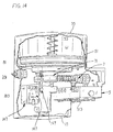
- the lubricant supply device of the present invention is designated in its entirety by the reference numeral 1.
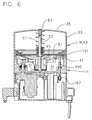
- the device comprises a housing generally designated 3 defining a reservoir R for holding a supply of lubricant, a distributor generally designated 5 connected to the housing for distributing lubricant to multiple points of lubrication, and a feed pump 7 in the housing for delivering lubricant from the reservoir to the distributor.
- the housing 3 comprises a plurality of parts, including a first part, generally designated 11, which may be referred to as a base for housing various components including the pump 7, a second part, generally designated 13, supported on the base 11 and forming the reservoir R, and a third part generally designated 15, below the base.
- the base 11 has a horizontal bottom wall 21, a rim 23 extending up from the bottom wall at its periphery, and an upper wall 27 spaced above the bottom wall and secured (as by fasteners) to the upper part of the rim.
- the bottom wall 21, rim 23 and upper wall 27 define a pump chamber 31 containing the feed pump 7.
- the second housing part 13 above the base 11 has a generally cylindric side wall 33 and an integral domed top wall 35 which combine to form the lubricant reservoir R.
- the bottom edge of the side wall 33 is supported on an annular step or shoulder 41 on the base 11.
- An O-ring 43 on the base 11 seals against the side wall 33 to ensure a sealing fit.
- the upper wall 27 of the base has openings 45 in it for flow of lubricant from the reservoir R into the pump chamber 31.
- a pusher (follower) plate 51 slidable on a vertical shaft 53 in the housing 13 overlies the lubricant in the reservoir R and has an annular seal 55 at its periphery which seals against the side wall 33 of the reservoir.
- the seal 55 is formed with a stiffening rib 59 (Fig. 4) to reduce flexure of the seal.
- a coil spring 61 surrounding the shaft 53 between the top wall 35 of the reservoir and the pusher plate 51 urges the plate downwardly to force lubricant through the openings 45 into the pump chamber 31.
- the upper housing part 13 is removably secured in place by means of a screw 63 extending down through a hole in the top wall 35 of the reservoir R into the upper end of the shaft 53.
- the shaft 53 is threadably mounted in a boss 67 formed as an intergral part of the bottom wall 21 of the housing base 11 and extends upward therefrom through a central hub 69 in the upper wall 27 into the reservoir R defined by the second housing pan 13.
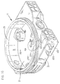
- An agitator 71 is rotatable on the shaft 53 immediately below the upper wall 27 of the base to feed lubricant from the reservoir toward the pump 7.
- the agitator 71 may have the configuration of a wheel having spokes 75 shaped to push lubricant in a downward direction as the agitator rotates on the shaft 53.
- the agitator is rotated by an electric motor 77 (Fig. 4) via a pinion and gearwheel drive 81.
- An eccentric 83 for driving the pump 7 is rotatable on the shaft 53 immediately below the agitator 71.
- the eccentric 83 is driven by the same electric motor 77 and is preferably (but not necessarily) formed as an integral part of the agitator, as shown in Fig. 9.
- the pump 7 is an expansible chamber pump comprising a piston 87 mounted for linear reciprocation in the horizontal bore 89 of a cylinder 91 mounted in an opening in the rim 23 of the base 11 of the housing.
- the cylinder 91 has one or more inlets 93 for entry of lubricant from the pump chamber 31 into the bore 89 of the cylinder, and one or more outlets 95 for exit of lubricant from the bore 89, a charge of lubricant being discharged from the cylinder during a forward pumping stroke of the piston 87 and charge of lubricant being drawn into the cylinder bore during a return stroke of the piston.
- the piston 87 is urged into contact with the eccentric 83 by a spring 97, so that rotation of the eccentric by the motor functions to reciprocate the piston in the cylinder 91.
- the eccentric 83 has a collar 98 of wear-resistant material thereon engageable by a cap 99 of wear resistant material on the piston.
- a spring-biased check valve, generally designated 100, mounted in the cylinder bore 89 prevents reverse flow of lubricant during a return stroke of the piston 87.
- the check valve 100 has a stem 101 slidable in a guide 102 fixedly mounted in the cylinder bore 89 for guiding the check valve as it moves between an open position during a forward stroke of the piston 87 and a closed position during a return stroke of the piston.
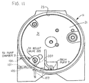
- lubricant is delivered from the pump 7 to one or more outlet openings 105 in the housing by passaging which includes an annular groove 106 in the housing surrounding the cylinder 91 and communicating with the pump outlet(s) 95, and a plurality of bores 107 drilled in the bottom wall 21 of the base 11, as shown in Figs. 10-12, the direction of flow being indicated by arrows. Bores 107 connect the annular groove 106 and the outlet openings 105, only one such outlet opening being shown in the drawings.
- the lubricant distributor 5 preferably has one or more inlets 111 (only one is illustrated in Fig. 7) and multiple outlets 113 connected to delivery lines (e.g., flexible hoses) for delivering lubricant to multiple points of lubrication.
- the outlets 113 are shown plugged in the drawings rather than connected to delivery lines).
- the distributor is preferably a progressive distributor of the type sold by Lincoln Industrial Corporation of St. Louis, Missouri, as an SSV18 divider block, part number 61937582-1. This type of distributor is described in detail in U.S. Patent No. 4,186,821.
- the distributor 5 (also referred to as a divider valve assembly) contains a series of positive displacement spools which are sequentially moved by incoming lubricant to deliver predetermined quantities of lubricant in series to the outlets 113 of the distributor. (In the embodiment shown in Figs. 1-14, the outlets 113 are on the bottom face of the distributor, but this orientation can vary). Other types of distributors may also be used. Regardless of the type used, however, an important aspect of this invention involves a sealing connection of the distributor 5 directly to the housing 3, without intervening hoses or other lines.
- the distributor 5 is connected directly to the base 11 of the housing 3, although it will be understood that the sealing connection may be between the distributor and other parts of the housing.
- the mating surfaces between the two parts is a downwardly facing surface 115 on the bottom wall 21 of the base and an upwardly facing surface 117 on the distributor.
- Each distributor inlet 111 comprises an inlet opening 119 in the connecting (mating) face 117 of the distributor.
- Each of these inlet openings 119 is sized and located to match up to a corresponding outlet opening 105 in the mating surface 115 of the bottom wall 21 of the base 11.
- the distributor is secured in place to the base 11 by means of screw fasteners 121, or in other suitable fashion.
- An O-ring 123 (Fig. 7) is provided in a counterbore 125 at the inlet opening 119 of the distributor and seals against the mating surface 115 of the base 11 around the outlet opening 105 to prevent leakage at this interface.
- a lubricant return passage 131 (Fig. 7) in the distributor 5 connects the various outlets 113 of the distributor. If one or more of these outlets 113 is not in use, each such outlet can be plugged, in which case the lubricant which would otherwise be discharged through the outlet 113 is directed into the return passage 131 which conveys the lubricant to a return outlet opening 135 in the upwardly facing mating surface 117 of the distributor.
- This opening 135 is directly opposite an inlet opening 137 of a return passage 139 in the bottom wall 21 of the base 11 of the housing 3.
- the return passage 139 in the base conveys lubricant back to the pump chamber 31.
- the electric motor 77 and an electronic programmable controller 147 are accommodated in a chamber 149 defined by a wall 153 of the third housing part 15 disposed on the underside of the base housing part 13 to ensure compactness of the overall device.
- the operating time of the feed pump 7 can be controlled by a sensor 151 which scans the movement of an indicator pin 153 of the lubricant distributor (see Fig. 13).
- the operating time and/or the rest time of the feed pump are adjustable.
- a membrane keyboard 181 and/or an operating state display 183 is/are provided on the housing 3, preferably on the second or third housing parts 13, 15, by which the controller 147 can be triggered, switched off and monitored (see Fig. 1).
- a sensor pin 191 extends up through the base 11 of the housing and into the reservoir R. This pin is mounted for sliding movement in the bottom wall 21 of the base 11 and is urged upwardly by a spring 195.
- the pusher plate 51 is engageable with the upper end of the pin 191 when the plate descends to a level indicating that the level of lubricant in the reservoir is low. As the plate 51 descends further, it pushes the pin 191 down.
- a suitable sensor 197 e.g., a magnet sensor mounted on the underside of the base 11 adjacent the lower end of the sensor pin 191 senses the downward motion of the pin and signals the controller 147 to display an "empty" or "low level” visual message on the display 183 so that the reservoir can be refilled.
- Refilling is accomplished by using a replenishment fitting 201 (Fig. 4) mounted in the rim 23 of the base 11 of the housing. Lubricant introduced into this fitting enters the pump chamber 31 and fills it to the point where additional lubricant flows up through the openings 45 in the upper wall 27 of the base 11 and into the reservoir R to fill it, the pusher plate 51 rising as the level in the reservoir rises.
- the second part 13 of the housing can also be transparent to provide a ready visual indication of the level of lubricant in the reservoir.
- a safety (relief) valve 205 (Fig. 5A) is also integrated into the housing 3. This valve communicates via a relief passage 207 with the supply passages 107 in the base 11. In the event there is a blockage in these passages 107 or in the distributor 5 sufficient to cause the pressure of the lubricant to rise above a predetermined level (e.g., 3000 psi [20.68 Mpa]), the safety valve opens to return additional lubricant delivered from the pump 7 back into the pump chamber 31.
- a predetermined level e.g., 3000 psi [20.68 Mpa]
- the distributor 5 has an injection port 211 (Fig. 3) by which lubricant can be injected directly into the distributor, bypassing the pump 7, as by using a grease gun or the like. This feature can be used in the event the pump fails, or to test for the location of a blockage in the system in the event there is no flow of lubricant from the distributor. If lubricant pumped into the distributor 5 via the port 211 does not exit the distributor, then the blockage is in the distributor; if the lubricant exits the distributor, then the blockage is upstream from the port in the housing 3 (e.g., in bores 107).
- lubricant supply device 1 When energized, the electric motor 79 rotates the agitator 71 and eccentric 83 on the shaft 53 via the pinion and gearwheel drive 81. Rotation of the agitator feeds lubricant down toward the inlet(s) 93 of the pump 7. Lubricant in the pump chamber 31 is replenished by additional lubricant flowing from the reservoir R through the openings 45 in the upper wall 27 of the base 11, as assisted by the spring-biased pusher plate 51.
- Rotation of the eccentric 83 drives the piston 87 of the pump through a forward stroke to discharge a quantity of lubricant through the outlet(s) 95 of the pump for delivery to the distributor 5 along a path constituted by the annular groove 106 and supply passages 107 in the bottom wall 21 of the base 11, the outlet opening(s) 105 of the supply passages 107, and across the interface between the mating connecting surfaces 115, 117 directly to the inlet opening(s) 119 of the distributor 5.
- the return spring 97 urges the piston 87 through a return stroke, generating a negative pressure which draws a new charge of lubricant into the bore 93 of the cylinder 95.
- the distributor 5 functions to distribute lubricant to multiple points of lubrication by means of lubricant lines connected to the outlet openings 113 of the distributor. Any outlet openings 113 not in use are simply plugged, causing lubricant to these outlets to be directed back to the pump chamber 31 via the return passages 131, 139 in the distributor 5 and base 11.
- the pusher plate 51 in the reservoir R will descend to a level at which it engages the sensor pin 191 and pushes it down.
- the motion sensor 197 detects this movement and signals the controller 147 to display a suitable low-level message on the display 183 indicating that the reservoir R needs to be refilled. Refilling is accomplished by using the refill fitting 201.
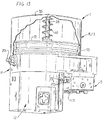
- Figs. 15-19 illustrate a lubricant supply device, generally designated 211, according to a second embodiment of the present invention.
- Device 211 is essentially identical to the first embodiment described above and corresponding parts are designated by corresponding reference numbers.
- a distributor is not mounted directly on the bottom surface 115 of the base 11 of the housing 3.
- a distributor 215 is connected to a different part of the housing, namely, an adaptor comprising a spacer block generally designated 217.
- the spacer block 217 is used to position the distributor 215 at a location where it is more readily accessible for connection to rigid conduit, such as stainless steel conduit, which may be required in certain applications for reasons of sanitation, as in the food and beverage industries.
- the distributor 215 is much the same as the distributor 5 described above except that it has side (rather than bottom) outlets 218 to facilitate this connection.
- a distributor suitable for this purpose is available from Lincoln Industrial Corporation of St. Louis, Missouri, as an SSV18 divider block, part number 61937588-1.
- the spacer block 217 is connected to the base 11 by suitable fasteners 219 (Fig. 15) in a position where the upper face 221 of the spacer block is directly against the downwardly facing surface 115 of the bottom wall 21 of the base (Fig. 18).
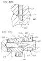
- the spacer block has a passage 223 in it extending essentially the full height of the block. As shown in Fig. 18A, this passage 223 communicates at its inlet (upper) end 227 with an adaptor supply passage 229 in the base 11, an O-ring seal 231 being provided to prevent leakage at the interface.
- the adaptor supply passage 229 communicates with the pump 7 via passage 107, as shown best in Figs. 10 and 12. As shown in Figs.
- the passage 223 has a lower end 233 which communicates with a circumferential groove 235 in a bolt 237 which extends through a clearance outlet hole 239 in the spacer block 217 and threads into a tapped inlet bore 241 in the distributor 215.
- the bolt has an axial passage 242 therein, the upstream (right in Fig. 18B) end of which communicates with groove 235 via one or more radial passages 243, and the downstream (left) end of which communicates with a supply passage 246 in the distributor 215 so that lubricant is delivered from the passage 223 in the spacer block 217 to the distributor supply passage 246 via groove 235, radial passage(s) 243, axial passage 242 and inlet bore 241.
- An O-ring seal 247 around the shank of the bolt 237 provides a seal between the head of the bolt and the spacer block 217.
- a second O-ring 249 around the shank provides a seal between the mating faces 251, 253 of spacer block 217 and the distributor 215.
- a manual injection block may be attached to the bottom wall 21 of the base 11 for injecting lubricant into the adaptor 217 for delivery to the distributor 215 in the event pump 7 fails or there is a blockage upstream of the adaptor inlet 227.
- the injection block 231 is attachable by fasteners 265 to the bottom wall 27 of the housing adjacent the adaptor 217.
- the injection block has a lubricant fitting 267 for connection to a source of lubricant (e.g., a grease gun) and a supply passage 271 with an outlet opening 273 which connects to the aforementioned opening 105 in the base 11.
- a source of lubricant e.g., a grease gun
- An O-ring seal 275 at the outlet opening 273 seals against the mating face 115 of the base 11 to prevent leakage.
- Lubricant injected into the injection block 261 flows through the supply passage 271 and through the opening 105 for delivery via passages 107 and 229 to spacer block passage 223.
- a supply device 1, 211 of the present invention eliminates the need for separate hoses or the like for connecting the housing 3 and pump 7 to the distributor 5, 215.
- the device is more compact and reliable in operation.
- the device is simple to operate, efficient and easy to maintain.
- the design also provides multiple distributor mounting configurations, including the configuration shown in Figs. 1-14 in which the distributor is "back mounted", i.e., connected directly to the base 11 of the housing, and the configuration shown in Figs. 15-20 where the distributor is "bottom mounted", i.e., connected directly to the adaptor part of the housing, and where the distributor may be more accessible for the use of rigid output lines.
Landscapes
- Engineering & Computer Science (AREA)
- General Engineering & Computer Science (AREA)
- Mechanical Engineering (AREA)
- Details Of Reciprocating Pumps (AREA)
- Pipeline Systems (AREA)
- Lubricants (AREA)
- General Details Of Gearings (AREA)
- Reciprocating Pumps (AREA)
- Feeding, Discharge, Calcimining, Fusing, And Gas-Generation Devices (AREA)
- Loading And Unloading Of Fuel Tanks Or Ships (AREA)
Applications Claiming Priority (8)
| Application Number | Priority Date | Filing Date | Title |
|---|---|---|---|
| DE19921685 | 1999-05-12 | ||
| DE19921685 | 1999-05-12 | ||
| DE19931730 | 1999-07-08 | ||
| DE19931730 | 1999-07-08 | ||
| US41495999A | 1999-10-12 | 1999-10-12 | |
| US414959 | 1999-10-12 | ||
| US542190 | 2000-04-04 | ||
| US09/542,190 US6244387B1 (en) | 1999-10-12 | 2000-04-04 | Lubricant supply device |
Publications (2)
| Publication Number | Publication Date |
|---|---|
| EP1052445A1 true EP1052445A1 (de) | 2000-11-15 |
| EP1052445B1 EP1052445B1 (de) | 2005-07-13 |
Family
ID=27438954
Family Applications (1)
| Application Number | Title | Priority Date | Filing Date |
|---|---|---|---|
| EP00303927A Expired - Lifetime EP1052445B1 (de) | 1999-05-12 | 2000-05-10 | Schmiermittelfördereinrichtung |
Country Status (5)
| Country | Link |
|---|---|
| EP (1) | EP1052445B1 (de) |
| JP (1) | JP2001019097A (de) |
| AT (1) | ATE299571T1 (de) |
| AU (1) | AU754930B2 (de) |
| DE (1) | DE60021226T2 (de) |
Cited By (10)
| Publication number | Priority date | Publication date | Assignee | Title |
|---|---|---|---|---|
| WO2002033309A1 (de) * | 2000-10-16 | 2002-04-25 | Lincoln Gmbh | Selbsttätige schmiereinrichtung |
| EP1253368A2 (de) * | 2001-04-24 | 2002-10-30 | Lube Corporation | Schmierungssystem und Ölzuführungsvorrichtung |
| EP1275895A1 (de) * | 2001-07-11 | 2003-01-15 | Dropsa S.P.A. | Schmiereinrichtung für periodische Zufuhr von dosierten Scmierstoffmengen für mehrere Benutzergeräte |
| WO2006108478A1 (de) * | 2005-04-12 | 2006-10-19 | Lincoln Gmbh | Einleitungsschmiereinrichtung |
| US8037968B2 (en) | 2004-10-04 | 2011-10-18 | Baier & Koppel Gmbh & Co. | Automatic lubrication apparatus |
| US8052402B2 (en) | 2008-10-20 | 2011-11-08 | Lincoln Industrial Corporation | Hand operated pump |
| US8783418B2 (en) | 2004-05-06 | 2014-07-22 | Natasa Enterprises Ltd | Automatic motor driven in-line piston pump lubricator |
| US9441613B2 (en) | 2011-08-30 | 2016-09-13 | Stephania Holdings Inc. | Methods of controlling a lubricator apparatus, methods of communication, and apparatuses and systems |
| WO2020258076A1 (en) * | 2019-06-26 | 2020-12-30 | Graco Minnesota Inc. | Heated lubricant pump |
| DE102004061447B4 (de) | 2004-12-17 | 2022-04-28 | Willy Vogel Aktiengesellschaft | Autarkes Hochdruck-Schmieraggregat |
Families Citing this family (2)
| Publication number | Priority date | Publication date | Assignee | Title |
|---|---|---|---|---|
| DE202012101700U1 (de) * | 2012-05-09 | 2013-05-10 | Tekawe Tribo- Und Industrietechnik Gmbh | Vorrichtung für eine Zentralschmiereinrichtung an einer Anlage |
| KR101485168B1 (ko) * | 2013-09-06 | 2015-01-28 | 주식회사 태성 | 윤활유 공급용 펌프 |
Citations (6)
| Publication number | Priority date | Publication date | Assignee | Title |
|---|---|---|---|---|
| GB1186996A (en) * | 1967-06-16 | 1970-04-08 | Eaton Yale & Towne | Centralised Cyclic Lubrication System. |
| US4186821A (en) | 1978-05-15 | 1980-02-05 | McNeill Corporation | Lubricating apparatus |
| EP0313821A1 (de) * | 1987-10-19 | 1989-05-03 | DROPSA S.p.A. | Modularer hydraulischer Progressivverteiler für Schmiersysteme |
| US5542498A (en) * | 1990-12-31 | 1996-08-06 | Uni-Mist, Inc. | Pulse action mist lubrication system |
| US5662023A (en) * | 1995-09-15 | 1997-09-02 | Premier Lubrication Systems, Inc. | Replaceable cylinder piston assembly for a lubricator pump |
| DE19809620C1 (de) * | 1998-03-06 | 1999-09-30 | Lincoln Gmbh | Vorrichtung zur Inhaltskontrolle eines Behälters |
Family Cites Families (4)
| Publication number | Priority date | Publication date | Assignee | Title |
|---|---|---|---|---|
| GB711937A (en) * | 1952-06-20 | 1954-07-14 | Dewandre Co Ltd C | Improvements in or relating to means for lubricating vehicle chassis |
| US5165502A (en) * | 1990-08-28 | 1992-11-24 | Daikin Industries Ltd. | One-main pipe type centralized lubrication apparatus |
| DE4100723C2 (de) * | 1991-01-10 | 1994-01-05 | Vogel Willi Ag | Zentralschmieraggregat |
| US5285871A (en) * | 1992-08-17 | 1994-02-15 | Mechanical Tool & Engineering Co. | System for distributing viscous lubricant |
-
2000
- 2000-05-04 AU AU32509/00A patent/AU754930B2/en not_active Ceased
- 2000-05-10 AT AT00303927T patent/ATE299571T1/de not_active IP Right Cessation
- 2000-05-10 DE DE60021226T patent/DE60021226T2/de not_active Expired - Lifetime
- 2000-05-10 EP EP00303927A patent/EP1052445B1/de not_active Expired - Lifetime
- 2000-05-12 JP JP2000140368A patent/JP2001019097A/ja active Pending
Patent Citations (6)
| Publication number | Priority date | Publication date | Assignee | Title |
|---|---|---|---|---|
| GB1186996A (en) * | 1967-06-16 | 1970-04-08 | Eaton Yale & Towne | Centralised Cyclic Lubrication System. |
| US4186821A (en) | 1978-05-15 | 1980-02-05 | McNeill Corporation | Lubricating apparatus |
| EP0313821A1 (de) * | 1987-10-19 | 1989-05-03 | DROPSA S.p.A. | Modularer hydraulischer Progressivverteiler für Schmiersysteme |
| US5542498A (en) * | 1990-12-31 | 1996-08-06 | Uni-Mist, Inc. | Pulse action mist lubrication system |
| US5662023A (en) * | 1995-09-15 | 1997-09-02 | Premier Lubrication Systems, Inc. | Replaceable cylinder piston assembly for a lubricator pump |
| DE19809620C1 (de) * | 1998-03-06 | 1999-09-30 | Lincoln Gmbh | Vorrichtung zur Inhaltskontrolle eines Behälters |
Cited By (17)
| Publication number | Priority date | Publication date | Assignee | Title |
|---|---|---|---|---|
| WO2002033309A1 (de) * | 2000-10-16 | 2002-04-25 | Lincoln Gmbh | Selbsttätige schmiereinrichtung |
| EP1253368A2 (de) * | 2001-04-24 | 2002-10-30 | Lube Corporation | Schmierungssystem und Ölzuführungsvorrichtung |
| EP1253368A3 (de) * | 2001-04-24 | 2004-01-07 | Lube Corporation | Schmierungssystem und Ölzuführungsvorrichtung |
| EP1275895A1 (de) * | 2001-07-11 | 2003-01-15 | Dropsa S.P.A. | Schmiereinrichtung für periodische Zufuhr von dosierten Scmierstoffmengen für mehrere Benutzergeräte |
| US8783418B2 (en) | 2004-05-06 | 2014-07-22 | Natasa Enterprises Ltd | Automatic motor driven in-line piston pump lubricator |
| US8037968B2 (en) | 2004-10-04 | 2011-10-18 | Baier & Koppel Gmbh & Co. | Automatic lubrication apparatus |
| US8596418B2 (en) | 2004-10-04 | 2013-12-03 | Baier & Koppel Gmbh & Co. | Automatic lubrication apparatus |
| DE102004061447B4 (de) | 2004-12-17 | 2022-04-28 | Willy Vogel Aktiengesellschaft | Autarkes Hochdruck-Schmieraggregat |
| WO2006108478A1 (de) * | 2005-04-12 | 2006-10-19 | Lincoln Gmbh | Einleitungsschmiereinrichtung |
| EA011476B1 (ru) * | 2005-04-12 | 2009-04-28 | Линкольн Гмбх | Одномагистральное смазочное устройство |
| CN101156021B (zh) * | 2005-04-12 | 2011-09-07 | 林肯有限公司 | 润滑剂供给装置 |
| US8365867B2 (en) | 2005-04-12 | 2013-02-05 | Lincoln Gmbh | Feeding lubricating device |
| US8052402B2 (en) | 2008-10-20 | 2011-11-08 | Lincoln Industrial Corporation | Hand operated pump |
| US9441613B2 (en) | 2011-08-30 | 2016-09-13 | Stephania Holdings Inc. | Methods of controlling a lubricator apparatus, methods of communication, and apparatuses and systems |
| WO2020258076A1 (en) * | 2019-06-26 | 2020-12-30 | Graco Minnesota Inc. | Heated lubricant pump |
| CN113906251A (zh) * | 2019-06-26 | 2022-01-07 | 固瑞克明尼苏达有限公司 | 可加热的润滑剂泵 |
| CN113906251B (zh) * | 2019-06-26 | 2023-08-25 | 固瑞克明尼苏达有限公司 | 可加热的润滑剂泵 |
Also Published As
| Publication number | Publication date |
|---|---|
| AU3250900A (en) | 2000-11-16 |
| DE60021226T2 (de) | 2006-01-12 |
| JP2001019097A (ja) | 2001-01-23 |
| ATE299571T1 (de) | 2005-07-15 |
| AU754930B2 (en) | 2002-11-28 |
| DE60021226D1 (de) | 2005-08-18 |
| EP1052445B1 (de) | 2005-07-13 |
Similar Documents
| Publication | Publication Date | Title |
|---|---|---|
| US6244387B1 (en) | Lubricant supply device | |
| EP1052445B1 (de) | Schmiermittelfördereinrichtung | |
| KR102133734B1 (ko) | 전자 펌프 모터 제어 | |
| US8978825B2 (en) | Dual-line pump unit, lubrication system, and related apparatus and method | |
| CN105135194B (zh) | 泵系统 | |
| US7059450B2 (en) | Automatic lubrication system | |
| KR101027653B1 (ko) | 그리스 윤활시스템용 펌프 | |
| US20040129499A1 (en) | Lubricant supply apparatus and system | |
| KR101287830B1 (ko) | 그리스 용기의 교환이 가능한 진동 방지형 그리스 토출장치 | |
| US4577728A (en) | Lubricant metering valve | |
| MXPA00004570A (en) | Lubricant supply device | |
| KR200201377Y1 (ko) | 그리스 주입기 | |
| JP2003340747A (ja) | 油圧式打撃装置のための自動給脂装置 | |
| DE20009183U1 (de) | Schmierstoffgeber für ein rotierendes Bauteil, insbesondere eine Bearbeitungsspindel |
Legal Events
| Date | Code | Title | Description |
|---|---|---|---|
| PUAI | Public reference made under article 153(3) epc to a published international application that has entered the european phase |
Free format text: ORIGINAL CODE: 0009012 |
|
| AK | Designated contracting states |
Kind code of ref document: A1 Designated state(s): AT BE CH CY DE DK ES FI FR GB GR IE IT LI LU MC NL PT SE |
|
| AX | Request for extension of the european patent |
Free format text: AL;LT;LV;MK;RO;SI |
|
| 17P | Request for examination filed |
Effective date: 20010330 |
|
| AKX | Designation fees paid |
Free format text: AT BE CH CY DE DK ES FI FR GB GR IE IT LI LU MC NL PT SE |
|
| 17Q | First examination report despatched |
Effective date: 20040331 |
|
| RAP1 | Party data changed (applicant data changed or rights of an application transferred) |
Owner name: LINCOLN GMBH & CO. KG |
|
| GRAP | Despatch of communication of intention to grant a patent |
Free format text: ORIGINAL CODE: EPIDOSNIGR1 |
|
| GRAS | Grant fee paid |
Free format text: ORIGINAL CODE: EPIDOSNIGR3 |
|
| GRAA | (expected) grant |
Free format text: ORIGINAL CODE: 0009210 |
|
| AK | Designated contracting states |
Kind code of ref document: B1 Designated state(s): AT BE CH CY DE DK ES FI FR GB GR IE IT LI LU MC NL PT SE |
|
| PG25 | Lapsed in a contracting state [announced via postgrant information from national office to epo] |
Ref country code: CH Free format text: LAPSE BECAUSE OF FAILURE TO SUBMIT A TRANSLATION OF THE DESCRIPTION OR TO PAY THE FEE WITHIN THE PRESCRIBED TIME-LIMIT Effective date: 20050713 Ref country code: LI Free format text: LAPSE BECAUSE OF FAILURE TO SUBMIT A TRANSLATION OF THE DESCRIPTION OR TO PAY THE FEE WITHIN THE PRESCRIBED TIME-LIMIT Effective date: 20050713 Ref country code: FI Free format text: LAPSE BECAUSE OF FAILURE TO SUBMIT A TRANSLATION OF THE DESCRIPTION OR TO PAY THE FEE WITHIN THE PRESCRIBED TIME-LIMIT Effective date: 20050713 Ref country code: BE Free format text: LAPSE BECAUSE OF FAILURE TO SUBMIT A TRANSLATION OF THE DESCRIPTION OR TO PAY THE FEE WITHIN THE PRESCRIBED TIME-LIMIT Effective date: 20050713 Ref country code: AT Free format text: LAPSE BECAUSE OF FAILURE TO SUBMIT A TRANSLATION OF THE DESCRIPTION OR TO PAY THE FEE WITHIN THE PRESCRIBED TIME-LIMIT Effective date: 20050713 |
|
| REG | Reference to a national code |
Ref country code: GB Ref legal event code: FG4D |
|
| REG | Reference to a national code |
Ref country code: CH Ref legal event code: EP |
|
| REG | Reference to a national code |
Ref country code: IE Ref legal event code: FG4D |
|
| REF | Corresponds to: |
Ref document number: 60021226 Country of ref document: DE Date of ref document: 20050818 Kind code of ref document: P |
|
| PG25 | Lapsed in a contracting state [announced via postgrant information from national office to epo] |
Ref country code: SE Free format text: LAPSE BECAUSE OF FAILURE TO SUBMIT A TRANSLATION OF THE DESCRIPTION OR TO PAY THE FEE WITHIN THE PRESCRIBED TIME-LIMIT Effective date: 20051013 Ref country code: GR Free format text: LAPSE BECAUSE OF FAILURE TO SUBMIT A TRANSLATION OF THE DESCRIPTION OR TO PAY THE FEE WITHIN THE PRESCRIBED TIME-LIMIT Effective date: 20051013 Ref country code: DK Free format text: LAPSE BECAUSE OF FAILURE TO SUBMIT A TRANSLATION OF THE DESCRIPTION OR TO PAY THE FEE WITHIN THE PRESCRIBED TIME-LIMIT Effective date: 20051013 |
|
| PG25 | Lapsed in a contracting state [announced via postgrant information from national office to epo] |
Ref country code: PT Free format text: LAPSE BECAUSE OF FAILURE TO SUBMIT A TRANSLATION OF THE DESCRIPTION OR TO PAY THE FEE WITHIN THE PRESCRIBED TIME-LIMIT Effective date: 20051219 |
|
| REG | Reference to a national code |
Ref country code: CH Ref legal event code: PL |
|
| PG25 | Lapsed in a contracting state [announced via postgrant information from national office to epo] |
Ref country code: IE Free format text: LAPSE BECAUSE OF NON-PAYMENT OF DUE FEES Effective date: 20060510 |
|
| PLBE | No opposition filed within time limit |
Free format text: ORIGINAL CODE: 0009261 |
|
| STAA | Information on the status of an ep patent application or granted ep patent |
Free format text: STATUS: NO OPPOSITION FILED WITHIN TIME LIMIT |
|
| PG25 | Lapsed in a contracting state [announced via postgrant information from national office to epo] |
Ref country code: MC Free format text: LAPSE BECAUSE OF NON-PAYMENT OF DUE FEES Effective date: 20060531 |
|
| 26N | No opposition filed |
Effective date: 20060418 |
|
| EN | Fr: translation not filed | ||
| PG25 | Lapsed in a contracting state [announced via postgrant information from national office to epo] |
Ref country code: FR Free format text: LAPSE BECAUSE OF FAILURE TO SUBMIT A TRANSLATION OF THE DESCRIPTION OR TO PAY THE FEE WITHIN THE PRESCRIBED TIME-LIMIT Effective date: 20060908 |
|
| REG | Reference to a national code |
Ref country code: IE Ref legal event code: MM4A |
|
| PG25 | Lapsed in a contracting state [announced via postgrant information from national office to epo] |
Ref country code: LU Free format text: LAPSE BECAUSE OF NON-PAYMENT OF DUE FEES Effective date: 20060510 |
|
| PG25 | Lapsed in a contracting state [announced via postgrant information from national office to epo] |
Ref country code: CY Free format text: LAPSE BECAUSE OF FAILURE TO SUBMIT A TRANSLATION OF THE DESCRIPTION OR TO PAY THE FEE WITHIN THE PRESCRIBED TIME-LIMIT Effective date: 20050713 Ref country code: FR Free format text: LAPSE BECAUSE OF FAILURE TO SUBMIT A TRANSLATION OF THE DESCRIPTION OR TO PAY THE FEE WITHIN THE PRESCRIBED TIME-LIMIT Effective date: 20050713 |
|
| PG25 | Lapsed in a contracting state [announced via postgrant information from national office to epo] |
Ref country code: ES Free format text: LAPSE BECAUSE OF NON-PAYMENT OF DUE FEES Effective date: 20060531 |
|
| REG | Reference to a national code |
Ref country code: DE Ref legal event code: R082 Ref document number: 60021226 Country of ref document: DE Representative=s name: W.P.THOMPSON & CO., GB Ref country code: DE Ref legal event code: R082 Ref document number: 60021226 Country of ref document: DE Representative=s name: KEIL & SCHAAFHAUSEN PATENT- UND RECHTSANWAELTE, DE |
|
| REG | Reference to a national code |
Ref country code: DE Ref legal event code: R082 Ref document number: 60021226 Country of ref document: DE Representative=s name: KEIL & SCHAAFHAUSEN PATENT- UND RECHTSANWAELTE, DE |
|
| REG | Reference to a national code |
Ref country code: DE Ref legal event code: R082 Ref document number: 60021226 Country of ref document: DE Representative=s name: KEIL & SCHAAFHAUSEN PATENT- UND RECHTSANWAELTE, DE Effective date: 20120710 Ref country code: DE Ref legal event code: R082 Ref document number: 60021226 Country of ref document: DE Representative=s name: KEIL & SCHAAFHAUSEN PATENT- UND RECHTSANWAELTE, DE Effective date: 20141202 Ref country code: DE Ref legal event code: R081 Ref document number: 60021226 Country of ref document: DE Owner name: SKF LUBRICATION SYSTEMS GERMANY GMBH, DE Free format text: FORMER OWNER: LINCOLN GMBH & CO. KG, 69190 WALLDORF, DE Effective date: 20141202 |
|
| PGFP | Annual fee paid to national office [announced via postgrant information from national office to epo] |
Ref country code: NL Payment date: 20170526 Year of fee payment: 18 |
|
| PGFP | Annual fee paid to national office [announced via postgrant information from national office to epo] |
Ref country code: FR Payment date: 20170822 Year of fee payment: 11 |
|
| PGFP | Annual fee paid to national office [announced via postgrant information from national office to epo] |
Ref country code: IT Payment date: 20170524 Year of fee payment: 18 |
|
| REG | Reference to a national code |
Ref country code: NL Ref legal event code: MM Effective date: 20180601 |
|
| GBPC | Gb: european patent ceased through non-payment of renewal fee |
Effective date: 20180510 |
|
| PG25 | Lapsed in a contracting state [announced via postgrant information from national office to epo] |
Ref country code: NL Free format text: LAPSE BECAUSE OF NON-PAYMENT OF DUE FEES Effective date: 20180601 Ref country code: IT Free format text: LAPSE BECAUSE OF NON-PAYMENT OF DUE FEES Effective date: 20180510 Ref country code: GB Free format text: LAPSE BECAUSE OF NON-PAYMENT OF DUE FEES Effective date: 20180510 |
|
| PGFP | Annual fee paid to national office [announced via postgrant information from national office to epo] |
Ref country code: DE Payment date: 20190731 Year of fee payment: 20 |
|
| REG | Reference to a national code |
Ref country code: DE Ref legal event code: R071 Ref document number: 60021226 Country of ref document: DE |