EP1052385B1 - Procédé pour établir un diagnostic d'un catalyseur ayant des caractéristiques d'oxydation d'hydrocarbures - Google Patents
Procédé pour établir un diagnostic d'un catalyseur ayant des caractéristiques d'oxydation d'hydrocarbures Download PDFInfo
- Publication number
- EP1052385B1 EP1052385B1 EP00108946A EP00108946A EP1052385B1 EP 1052385 B1 EP1052385 B1 EP 1052385B1 EP 00108946 A EP00108946 A EP 00108946A EP 00108946 A EP00108946 A EP 00108946A EP 1052385 B1 EP1052385 B1 EP 1052385B1
- Authority
- EP
- European Patent Office
- Prior art keywords
- temperature
- internal combustion
- catalyst
- combustion engine
- catalytic converter
- Prior art date
- Legal status (The legal status is an assumption and is not a legal conclusion. Google has not performed a legal analysis and makes no representation as to the accuracy of the status listed.)
- Expired - Lifetime
Links
Images
Classifications
-
- F—MECHANICAL ENGINEERING; LIGHTING; HEATING; WEAPONS; BLASTING
- F01—MACHINES OR ENGINES IN GENERAL; ENGINE PLANTS IN GENERAL; STEAM ENGINES
- F01N—GAS-FLOW SILENCERS OR EXHAUST APPARATUS FOR MACHINES OR ENGINES IN GENERAL; GAS-FLOW SILENCERS OR EXHAUST APPARATUS FOR INTERNAL COMBUSTION ENGINES
- F01N9/00—Electrical control of exhaust gas treating apparatus
- F01N9/005—Electrical control of exhaust gas treating apparatus using models instead of sensors to determine operating characteristics of exhaust systems, e.g. calculating catalyst temperature instead of measuring it directly
-
- F—MECHANICAL ENGINEERING; LIGHTING; HEATING; WEAPONS; BLASTING
- F01—MACHINES OR ENGINES IN GENERAL; ENGINE PLANTS IN GENERAL; STEAM ENGINES
- F01N—GAS-FLOW SILENCERS OR EXHAUST APPARATUS FOR MACHINES OR ENGINES IN GENERAL; GAS-FLOW SILENCERS OR EXHAUST APPARATUS FOR INTERNAL COMBUSTION ENGINES
- F01N11/00—Monitoring or diagnostic devices for exhaust-gas treatment apparatus, e.g. for catalytic activity
- F01N11/002—Monitoring or diagnostic devices for exhaust-gas treatment apparatus, e.g. for catalytic activity the diagnostic devices measuring or estimating temperature or pressure in, or downstream of the exhaust apparatus
- F01N11/005—Monitoring or diagnostic devices for exhaust-gas treatment apparatus, e.g. for catalytic activity the diagnostic devices measuring or estimating temperature or pressure in, or downstream of the exhaust apparatus the temperature or pressure being estimated, e.g. by means of a theoretical model
-
- F—MECHANICAL ENGINEERING; LIGHTING; HEATING; WEAPONS; BLASTING
- F01—MACHINES OR ENGINES IN GENERAL; ENGINE PLANTS IN GENERAL; STEAM ENGINES
- F01N—GAS-FLOW SILENCERS OR EXHAUST APPARATUS FOR MACHINES OR ENGINES IN GENERAL; GAS-FLOW SILENCERS OR EXHAUST APPARATUS FOR INTERNAL COMBUSTION ENGINES
- F01N3/00—Exhaust or silencing apparatus having means for purifying, rendering innocuous, or otherwise treating exhaust
- F01N3/08—Exhaust or silencing apparatus having means for purifying, rendering innocuous, or otherwise treating exhaust for rendering innocuous
- F01N3/0807—Exhaust or silencing apparatus having means for purifying, rendering innocuous, or otherwise treating exhaust for rendering innocuous by using absorbents or adsorbents
- F01N3/0828—Exhaust or silencing apparatus having means for purifying, rendering innocuous, or otherwise treating exhaust for rendering innocuous by using absorbents or adsorbents characterised by the absorbed or adsorbed substances
- F01N3/0842—Nitrogen oxides
-
- F—MECHANICAL ENGINEERING; LIGHTING; HEATING; WEAPONS; BLASTING
- F01—MACHINES OR ENGINES IN GENERAL; ENGINE PLANTS IN GENERAL; STEAM ENGINES
- F01N—GAS-FLOW SILENCERS OR EXHAUST APPARATUS FOR MACHINES OR ENGINES IN GENERAL; GAS-FLOW SILENCERS OR EXHAUST APPARATUS FOR INTERNAL COMBUSTION ENGINES
- F01N2550/00—Monitoring or diagnosing the deterioration of exhaust systems
- F01N2550/02—Catalytic activity of catalytic converters
-
- F—MECHANICAL ENGINEERING; LIGHTING; HEATING; WEAPONS; BLASTING
- F01—MACHINES OR ENGINES IN GENERAL; ENGINE PLANTS IN GENERAL; STEAM ENGINES
- F01N—GAS-FLOW SILENCERS OR EXHAUST APPARATUS FOR MACHINES OR ENGINES IN GENERAL; GAS-FLOW SILENCERS OR EXHAUST APPARATUS FOR INTERNAL COMBUSTION ENGINES
- F01N2570/00—Exhaust treating apparatus eliminating, absorbing or adsorbing specific elements or compounds
- F01N2570/12—Hydrocarbons
-
- F—MECHANICAL ENGINEERING; LIGHTING; HEATING; WEAPONS; BLASTING
- F02—COMBUSTION ENGINES; HOT-GAS OR COMBUSTION-PRODUCT ENGINE PLANTS
- F02D—CONTROLLING COMBUSTION ENGINES
- F02D41/00—Electrical control of supply of combustible mixture or its constituents
- F02D41/30—Controlling fuel injection
- F02D41/38—Controlling fuel injection of the high pressure type
- F02D41/40—Controlling fuel injection of the high pressure type with means for controlling injection timing or duration
- F02D41/402—Multiple injections
- F02D41/405—Multiple injections with post injections
-
- Y—GENERAL TAGGING OF NEW TECHNOLOGICAL DEVELOPMENTS; GENERAL TAGGING OF CROSS-SECTIONAL TECHNOLOGIES SPANNING OVER SEVERAL SECTIONS OF THE IPC; TECHNICAL SUBJECTS COVERED BY FORMER USPC CROSS-REFERENCE ART COLLECTIONS [XRACs] AND DIGESTS
- Y02—TECHNOLOGIES OR APPLICATIONS FOR MITIGATION OR ADAPTATION AGAINST CLIMATE CHANGE
- Y02T—CLIMATE CHANGE MITIGATION TECHNOLOGIES RELATED TO TRANSPORTATION
- Y02T10/00—Road transport of goods or passengers
- Y02T10/10—Internal combustion engine [ICE] based vehicles
- Y02T10/40—Engine management systems
Definitions
- the present invention relates to a method for diagnosis of a hydrocarbon oxidizing properties Catalyst, which is arranged in the exhaust tract of an internal combustion engine is.
- the efficiency of the hydrocarbon oxidizing properties Showing catalyst is for the quality of the exhaust gas cleaning essential. Due to aging and poisoning the convertibility of the catalyst decreases and with it its efficiency.
- JP 04060106A is a method for diagnosing a Catalyst known in which the temperature of the catalyst is measured and the temperature gradient from the catalyst temperature with normal operation of the internal combustion engine and the catalyst temperature after changing the Air / fuel ratio is calculated too rich. If the temperature gradient calculated in this way does not lie within a permissible range, it is converted to a deteriorated operating condition of the catalyst closed.
- a method is known from EP 0 609 527 A1 and WO 94/04800 known for the diagnosis of a catalyst in which during a Thrust shutdown phase the ignition of a cylinder Internal combustion engine switched off and briefly via the injection valve Fuel is injected without igniting it. This amount of fuel injected is shared with the exhaust gas from the other, regularly operated cylinders the catalytic converter fed and caused an exothermic reaction its catalytic surface by a temperature sensor is recorded.
- the overrun cut-off phase is usually very short, it is hardly possible during this Time to measure a temperature rise behind the catalytic converter.
- the invention has for its object a method for Diagnosis of a hydrocarbon-oxidizing property Specify catalyst in which only one temperature measurement is required and still high diagnostic certainty is achieved.
- the invention takes advantage of the fact that the production is exothermic Energy in the oxidation of hydrocarbons each varies in size depending on the efficiency of the catalyst.
- the method is also in an advantageous further development in the case of non-stationary operating states of the internal combustion engine easy to do.
- the temperature downstream of the Catalyst for example, depending on the speed, filling and fuel mass etc. continuously modeled.
- the model is diagnosed based on the measured temperature adjusted so that the model temperature before the additional The fuel supply is equal to the measured temperature.
- the post-injection creates a difference between measured temperature and model temperature, the one Measure of the exothermic energy that results from the implementation of the Hydrocarbons were formed in the catalyst.
- this temperature difference determines the efficiency of the catalyst become.
- the process according to the invention has the advantage that without deterioration a temperature sensor for diagnostic reliability can be saved.
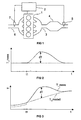
- FIG 1 shows an internal combustion engine schematically, at which the procedure for diagnosing the catalyst should be applied. There are only those elements included for the understanding of the invention are essential.
- An internal combustion engine 1 has an exhaust tract 3 in which a Catalyst 4 is arranged, downstream of which there is a temperature sensor 5 is located. This temperature sensor 5 is with a Operating control unit 2 of the internal combustion engine 1 connected, that controls and regulates the operation of the internal combustion engine 1.
- the internal combustion engine 1 also has an intake tract 6 on, in which an air mass meter 7 is arranged, the Measurement signals are read out by the operating control unit 2.
- the operating control device 2 detects by means of the air mass meter 7 that sucked in by the internal combustion engine 1 Air mass and determines the corresponding one Amount of fuel from an injection system (not shown) the internal combustion engine is to be injected.
- the internal combustion engine 1 can be a direct-injection, lean-fueled Internal combustion engine, where the fuel is direct is injected into the combustion chambers of the cylinders and with an air / fuel ratio of over 1 is burned.
- other internal combustion engines are also conceivable whom the described method can be used.
- the exhaust gas in the exhaust tract 3 of the internal combustion engine 1 is in the Catalyst 4 by oxidation of pollutants such as carbon monoxide and cleaned hydrocarbons.
- the catalyst 4 is a conventional 3-way catalytic converter, which is due to the lean operation but only shows oxidizing properties.
- the cyclic In the exhaust tract 3 there is a downstream of the catalyst 4 (not shown) arranged NOx storage catalyst, the cyclic is loaded and unloaded.
- the efficiency of the loading this NOx storage catalytic converter depends heavily on the hydrocarbon concentration in the exhaust gas, which is the NOx storage catalytic converter is fed from. A high hydrocarbon concentration reduces the efficiency of the NOx storage catalytic converter. Therefore, the catalytic converter 4 is in the exhaust tract 3 arranged, the unburned hydrocarbon oxidized. Thereby the efficiency of the NOx storage catalyst is improved and the hydrocarbon emissions especially in the warm-up phase are reduced.
- the catalyst 4 shows the operating time of the Internal combustion engine 1 no constant conversion behavior, he ages. This aging changes even at constant Conditions, e.g. regarding operating point and raw exhaust gas composition, the hydrocarbon content in the exhaust gas downstream of the catalyst 4 and in front of the NOx storage catalyst.
- a cylinder is diagnosed during the extension cycle fuel is additionally supplied to the internal combustion engine 1. In the case of a direct injection internal combustion engine this is done by post-injection into the push-out cycle.
- the catalyst 4 unburned hydrocarbons supplied.
- the amount of this Hydrocarbon exposure is due to the duration of the post-injection and the exhaust gas mass flowing in the exhaust tract 3 certainly.
- the operating control unit 2 calculates the latter the air mass indicated by the air mass meter 7 in the intake tract 6, as well as other operating parameters of the internal combustion engine 1.
- the operating control device 2 monitors after this post-injection the temperature at the temperature sensor 5 downstream of the catalyst 4th
- FIG. 2 An exemplary temperature profile is shown in FIG. 2.
- the internal combustion engine 1 on one operated constant operating point at which the temperature of the Exhaust gas downstream of the catalyst 4 without the post-injection would remain normal (dashed line).
- the temperature increase dT the measured temperature T_mess is due to that with the oxidation which causes hydrocarbons to be released.
- the operating control device 2 determines one depending on the operating point Threshold value for dT, below which the catalyst 4 is diagnosed as defective.
- the operating control device 2 again determines whether the catalyst 4 still has sufficient efficiency. falls below dT an operating point dependent threshold value, see the catalyst is diagnosed as defective.
- the threshold value is chosen so that a value for dT is obtained by transforming the above equation, the operating point-dependent variations of M_LM, M_SLM, C and c A is taken into account, whereby c A can generally be assumed to be constant.
- the value for H must of course also be taken into account.
- dT can then be taken from a map that is over M_LM, M_SLM, H and C is spanned.
Landscapes
- Engineering & Computer Science (AREA)
- Chemical & Material Sciences (AREA)
- Combustion & Propulsion (AREA)
- Mechanical Engineering (AREA)
- General Engineering & Computer Science (AREA)
- Chemical Kinetics & Catalysis (AREA)
- Analytical Chemistry (AREA)
- Exhaust Gas After Treatment (AREA)
Claims (6)
- Procédé pour diagnostiquer un catalyseur (4) ayant des caractéristiques d'oxydation d'hydrocarbures, ce catalyseur étant disposé dans le trajet d'échappement (3) d'un moteur à combustion interne (1), le procédé comprenant l'introduction, dans une phase de mesure au cours du fonctionnement du moteur à combustion interne, de carburant additionnel dans les gaz d'échappement en aval du catalyseur (4) après le processus de combustion, le contrôle de l'évolution de la température des gaz d'échappement en aval du catalyseur (4), et la déclaration du catalyseur (4) comme défectueux si l'augmentation de température reste au-dessous d'une valeur de seuil.
- Procédé selon la revendication 1, caractérisé en ce que le diagnostic est effectué à un point de fonctionnement du moteur à combustion interne (1) auquel la température des gaz d'échappement resterait approximativement constante s'il n'y avait pas d'adjonction de carburant additionnel.
- Procédé selon la revendication 1, caractérisé en ce que la température en aval du catalyseur (4) est continuellement modélisée à partir de paramètres de fonctionnement du moteur à combustion interne (1), que la température modélisée (T_modell) est ajustée à la température mesurée (T_mess) avant le diagnostic, et que l'augmentation de température (dT) est déterminée au cours du diagnostic à partir de la différence entre la température modélisée et la température mesurée.
- Procédé selon l'une des revendications précédentes, caractérisé en ce que la quantité de carburant additionnellement introduit et/ou la valeur de seuil sont choisies en fonction du flux massique d'air aspiré par le moteur à combustion interne (1).
- Procédé selon la revendication 4, caractérisé en ce que la valeur de seuil est extraite d'une table caractéristique dressée en fonction d'une valeur représentant la quantité de carburant ajoutée, du flux massique d'air dans le trajet d'aspiration (6), et d'un coefficient dépendant du rapport air/carburant.
- Procédé selon l'une des revendications précédentes, caractérisé en ce que l'addition de carburant est effectuée dans un cylindre effectuant son temps d'échappement.
Applications Claiming Priority (2)
| Application Number | Priority Date | Filing Date | Title |
|---|---|---|---|
| DE19919588 | 1999-04-29 | ||
| DE19919588 | 1999-04-29 |
Publications (3)
| Publication Number | Publication Date |
|---|---|
| EP1052385A2 EP1052385A2 (fr) | 2000-11-15 |
| EP1052385A3 EP1052385A3 (fr) | 2001-10-17 |
| EP1052385B1 true EP1052385B1 (fr) | 2003-07-09 |
Family
ID=7906334
Family Applications (1)
| Application Number | Title | Priority Date | Filing Date |
|---|---|---|---|
| EP00108946A Expired - Lifetime EP1052385B1 (fr) | 1999-04-29 | 2000-04-27 | Procédé pour établir un diagnostic d'un catalyseur ayant des caractéristiques d'oxydation d'hydrocarbures |
Country Status (2)
| Country | Link |
|---|---|
| EP (1) | EP1052385B1 (fr) |
| DE (1) | DE50002799D1 (fr) |
Cited By (4)
| Publication number | Priority date | Publication date | Assignee | Title |
|---|---|---|---|---|
| CN101790624B (zh) * | 2007-08-31 | 2012-05-23 | 尤米科尔股份公司及两合公司 | 用于检验在车辆上的催化器的老化状态的方法 |
| DE102005015998B4 (de) * | 2005-04-07 | 2014-07-10 | Robert Bosch Gmbh | Katalysatordiagnoseverfahren |
| DE102014209960A1 (de) | 2013-06-13 | 2014-12-18 | Ford Global Technologies, Llc | Verfahren und Vorrichtung zum Bewerten der Funktionsfähigkeit eines SCR-Katalysators in einem Abgassystem eines Dieselmotors |
| DE102004054107B4 (de) * | 2003-11-10 | 2016-07-28 | Denso Corporation | Abgastemperatursensor-Fehlfunktionserfassungsgerät |
Families Citing this family (13)
| Publication number | Priority date | Publication date | Assignee | Title |
|---|---|---|---|---|
| JP4631123B2 (ja) * | 2000-03-16 | 2011-02-16 | マツダ株式会社 | エンジンの排気浄化装置 |
| DE10113010A1 (de) * | 2001-03-17 | 2002-09-19 | Bosch Gmbh Robert | Verfahren und Vorrichtung zur Überwachung eines Abgasnachbehandlungssystems |
| FR2833994B1 (fr) * | 2001-12-24 | 2004-02-27 | Renault | Procede et dispositif de controle de l'etat de fonctionnement d'un convertisseur catalytique d'une ligne d'echappement d'un moteur a combustion interne |
| JP4238788B2 (ja) | 2004-06-21 | 2009-03-18 | トヨタ自動車株式会社 | パティキュレートフィルタ異常判定方法 |
| FR2886347B1 (fr) * | 2005-05-31 | 2007-07-13 | Renault Sas | Procede et dispositif de detection de presence d'un systeme de traitement d'effluents gazeux dans une ligne d'echappement d'un moteur a combustion interne. |
| DE102007012701B4 (de) * | 2007-03-16 | 2016-05-19 | Robert Bosch Gmbh | Verfahren zur Funktionsüberwachung eines Oxidationskatalysators |
| FR2914693B1 (fr) * | 2007-04-06 | 2009-05-29 | Renault Sas | Procede et dispositif de diagnostic du fonctionnement d'un organe de traitement d'effluents gazeux |
| FR2914948B1 (fr) * | 2007-04-13 | 2009-06-05 | Renault Sas | Procede et dispositif de controle de l'etat de fonctionnement d'un convertisseur catalytique d'une ligne d'echappement d'un moteur a combustion interne |
| FR2916478A1 (fr) * | 2007-05-21 | 2008-11-28 | Peugeot Citroen Automobiles Sa | Methode et dispositif de controle d'un catalyseur de depollution de moteur diesel |
| DE102007045256A1 (de) * | 2007-09-21 | 2009-04-02 | Volkswagen Ag | Verfahren zum Prüfen der Funktionsfähigkeit eines Oxidationskatalysators einer Brennkraftmaschine |
| US8561393B2 (en) * | 2011-03-21 | 2013-10-22 | GM Global Technology Operations LLC | Method of determining if an oxidation catalyst is quenched or is not quenched |
| DE102014201072A1 (de) | 2013-02-01 | 2014-08-07 | Ford Global Technologies, Llc | Bestimmen eines Alterungsgrades eines Oxidationskatalysators |
| FR3005104B1 (fr) * | 2013-04-30 | 2015-04-10 | Renault Sa | Dispositif et procede de controle de l'etat de fonctionnement d'un organe de traitement d'effluents gazeux d'une ligne d'echappement d'un moteur a combustion interne |
Family Cites Families (5)
| Publication number | Priority date | Publication date | Assignee | Title |
|---|---|---|---|---|
| JPH03121240A (ja) * | 1989-10-02 | 1991-05-23 | Hitachi Ltd | 排気浄化用触媒故障診断法 |
| JPH0460106A (ja) * | 1990-06-29 | 1992-02-26 | Mazda Motor Corp | エンジンの制御装置 |
| KR100268751B1 (ko) * | 1992-08-17 | 2000-10-16 | 베. 마우스; 베. 디트리히 | 촉매변환기의 작동을 모니터링하기 위한 방법 |
| DE4302779C2 (de) * | 1993-02-02 | 1995-10-05 | Porsche Ag | Verfahren zur Überprüfung der Funktionstüchtigkeit von im Abgasstrang, von mit einer Brennkraftmaschine ausgerüsteten Kraftfahrzeugen eingesetzten Abgaskatalysatoren |
| JP3239698B2 (ja) * | 1995-07-25 | 2001-12-17 | トヨタ自動車株式会社 | 内燃機関の触媒劣化判定装置 |
-
2000
- 2000-04-27 DE DE50002799T patent/DE50002799D1/de not_active Expired - Lifetime
- 2000-04-27 EP EP00108946A patent/EP1052385B1/fr not_active Expired - Lifetime
Cited By (5)
| Publication number | Priority date | Publication date | Assignee | Title |
|---|---|---|---|---|
| DE102004054107B4 (de) * | 2003-11-10 | 2016-07-28 | Denso Corporation | Abgastemperatursensor-Fehlfunktionserfassungsgerät |
| DE102005015998B4 (de) * | 2005-04-07 | 2014-07-10 | Robert Bosch Gmbh | Katalysatordiagnoseverfahren |
| CN101790624B (zh) * | 2007-08-31 | 2012-05-23 | 尤米科尔股份公司及两合公司 | 用于检验在车辆上的催化器的老化状态的方法 |
| DE102014209960A1 (de) | 2013-06-13 | 2014-12-18 | Ford Global Technologies, Llc | Verfahren und Vorrichtung zum Bewerten der Funktionsfähigkeit eines SCR-Katalysators in einem Abgassystem eines Dieselmotors |
| DE102014209960B4 (de) | 2013-06-13 | 2020-07-02 | Ford Global Technologies, Llc | Verfahren und Vorrichtung zum Bewerten der Funktionsfähigkeit eines SCR-Katalysators in einem Abgassystem eines Dieselmotors |
Also Published As
| Publication number | Publication date |
|---|---|
| EP1052385A3 (fr) | 2001-10-17 |
| EP1052385A2 (fr) | 2000-11-15 |
| DE50002799D1 (de) | 2003-08-14 |
Similar Documents
| Publication | Publication Date | Title |
|---|---|---|
| EP1052385B1 (fr) | Procédé pour établir un diagnostic d'un catalyseur ayant des caractéristiques d'oxydation d'hydrocarbures | |
| EP1228301B1 (fr) | Procede pour controler le pot catalytique de gaz d'echappement d'un moteur a combustion interne | |
| EP1524417B1 (fr) | Moteur à combustion interne comprenant un turbocompresseur à gaz d'échappement et une injection d'air secondaire, ainsi qu'un diagnostic et une commande de l'injection d'air secondaire | |
| DE102006017065B4 (de) | Temperatursensor-Rationalitätsdiagnose bei einem Dieseloxidationskatalysator (DOC) | |
| DE102010046750B4 (de) | Verfahren zum Steuern von Kraftstoff eines fremdgezündeten Motors während Regenerieren eines Partikelfilters | |
| DE102017214898B4 (de) | Reformiersystem und Reformierstörungs-Diagnoseverfahren unter Verwendung eines Drucksensors | |
| EP1084331B1 (fr) | Dispositif et procede de surveillance de la capacite fonctionnelle d'un catalyseur pour moteur a combustion interne | |
| EP1192340B1 (fr) | Procede pour la verification d'un pot d'echappement catalytique a trois voies d'un moteur a combustion interne | |
| DE102013217622A1 (de) | Differenzdruckbasierte Aktivierung einer Partikelfilterdiagnose | |
| DE10319983B3 (de) | Verfahren und Vorrichtung zur Lambda-Regelung und zur Katalysatordiagnose bei einer Brennkraftmaschine | |
| DE102008025452A1 (de) | Überwachung der Leistung einer Lambdasonde | |
| WO2018104425A1 (fr) | Procédé et appareil de commande permettant de mettre en œuvre des diagnostics d'un système d'échappement d'un moteur à combustion interne | |
| DE102013010562A1 (de) | Verfahren zum Bestimmen einer HC-Konvertierungsfähigkeit eines Katalysators, zur Ausführung des Verfahrens eingerichtete Diagnoseeinrichtung sowie Kraftfahrzeug mit einer solchen | |
| DE102010047809A1 (de) | Systeme und Verfahren zum Steuern einer Regeneration von Stickoxidadsorbern | |
| DE10030064A1 (de) | Motorabgasreinigungsvorrichtung | |
| DE10039952C2 (de) | Verfahren zur Überprüfung einer Abgasrückführanlage | |
| WO2019170623A1 (fr) | Procédé permettant de faire fonctionner un moteur à allumage commandé, en particulier un véhicule automobile, ainsi que véhicule automobile | |
| EP1576270B1 (fr) | Procede de controle d'un convertisseur catalytique et dispositif de controle correspondant | |
| DE102012202679B3 (de) | Verfahren zur Einleitung und Aufrechterhaltung eines unterstöchiometrischen Betriebs einer Brennkraftmaschine und Brennkraftmaschine zur Durchführung eines derartigen Verfahrens | |
| DE112009004665T5 (de) | Katalysatoranormalitätsdiagnosevorrichtung | |
| DE102015200751B4 (de) | Verfahren zur Überwachung einer Abgasnachbehandlungsanlage eines Verbrennungsmotors sowie Steuerungseinrichtung für eine Abgasnachbehandlungsanlage | |
| DE19828928C2 (de) | Verfahren zur Überwachung des Abgasreinigungssystems einer Brennkraftmaschine | |
| DE102010003324A1 (de) | Verfahren zur Funktionsüberwachung eines Partikelfilters | |
| EP1422398A1 (fr) | Procédé pour diagnostiquer le fonctionnement d'un convertisseur cathalytique des gaz d'échappement | |
| EP3551856B1 (fr) | Procédé pour réaliser des diagnostics sur un système d'échappement d'un moteur à combustion interne |
Legal Events
| Date | Code | Title | Description |
|---|---|---|---|
| PUAI | Public reference made under article 153(3) epc to a published international application that has entered the european phase |
Free format text: ORIGINAL CODE: 0009012 |
|
| AK | Designated contracting states |
Kind code of ref document: A2 Designated state(s): DE FR GB Kind code of ref document: A2 Designated state(s): AT BE CH CY DE DK ES FI FR GB GR IE IT LI LU MC NL PT SE |
|
| AX | Request for extension of the european patent |
Free format text: AL;LT;LV;MK;RO;SI |
|
| PUAL | Search report despatched |
Free format text: ORIGINAL CODE: 0009013 |
|
| AK | Designated contracting states |
Kind code of ref document: A3 Designated state(s): AT BE CH CY DE DK ES FI FR GB GR IE IT LI LU MC NL PT SE |
|
| AX | Request for extension of the european patent |
Free format text: AL;LT;LV;MK;RO;SI |
|
| 17P | Request for examination filed |
Effective date: 20011119 |
|
| 17Q | First examination report despatched |
Effective date: 20020306 |
|
| AKX | Designation fees paid |
Free format text: DE FR GB |
|
| GRAH | Despatch of communication of intention to grant a patent |
Free format text: ORIGINAL CODE: EPIDOS IGRA |
|
| GRAH | Despatch of communication of intention to grant a patent |
Free format text: ORIGINAL CODE: EPIDOS IGRA |
|
| GRAA | (expected) grant |
Free format text: ORIGINAL CODE: 0009210 |
|
| AK | Designated contracting states |
Designated state(s): DE FR GB |
|
| REG | Reference to a national code |
Ref country code: GB Ref legal event code: FG4D Free format text: NOT ENGLISH |
|
| GBT | Gb: translation of ep patent filed (gb section 77(6)(a)/1977) | ||
| REF | Corresponds to: |
Ref document number: 50002799 Country of ref document: DE Date of ref document: 20030814 Kind code of ref document: P |
|
| ET | Fr: translation filed | ||
| PLBE | No opposition filed within time limit |
Free format text: ORIGINAL CODE: 0009261 |
|
| STAA | Information on the status of an ep patent application or granted ep patent |
Free format text: STATUS: NO OPPOSITION FILED WITHIN TIME LIMIT |
|
| 26N | No opposition filed |
Effective date: 20040414 |
|
| PGFP | Annual fee paid to national office [announced via postgrant information from national office to epo] |
Ref country code: FR Payment date: 20090414 Year of fee payment: 10 |
|
| PGFP | Annual fee paid to national office [announced via postgrant information from national office to epo] |
Ref country code: GB Payment date: 20090421 Year of fee payment: 10 |
|
| GBPC | Gb: european patent ceased through non-payment of renewal fee |
Effective date: 20100427 |
|
| REG | Reference to a national code |
Ref country code: FR Ref legal event code: ST Effective date: 20101230 |
|
| PG25 | Lapsed in a contracting state [announced via postgrant information from national office to epo] |
Ref country code: GB Free format text: LAPSE BECAUSE OF NON-PAYMENT OF DUE FEES Effective date: 20100427 |
|
| PG25 | Lapsed in a contracting state [announced via postgrant information from national office to epo] |
Ref country code: FR Free format text: LAPSE BECAUSE OF NON-PAYMENT OF DUE FEES Effective date: 20100430 |
|
| PGFP | Annual fee paid to national office [announced via postgrant information from national office to epo] |
Ref country code: DE Payment date: 20180430 Year of fee payment: 19 |
|
| REG | Reference to a national code |
Ref country code: DE Ref legal event code: R119 Ref document number: 50002799 Country of ref document: DE |
|
| PG25 | Lapsed in a contracting state [announced via postgrant information from national office to epo] |
Ref country code: DE Free format text: LAPSE BECAUSE OF NON-PAYMENT OF DUE FEES Effective date: 20191101 |