EP1052359A2 - Hinge - Google Patents
Hinge Download PDFInfo
- Publication number
- EP1052359A2 EP1052359A2 EP00109406A EP00109406A EP1052359A2 EP 1052359 A2 EP1052359 A2 EP 1052359A2 EP 00109406 A EP00109406 A EP 00109406A EP 00109406 A EP00109406 A EP 00109406A EP 1052359 A2 EP1052359 A2 EP 1052359A2
- Authority
- EP
- European Patent Office
- Prior art keywords
- hinge
- wing
- hinge according
- swivel
- slot
- Prior art date
- Legal status (The legal status is an assumption and is not a legal conclusion. Google has not performed a legal analysis and makes no representation as to the accuracy of the status listed.)
- Granted
Links
Images


Classifications
-
- E—FIXED CONSTRUCTIONS
- E05—LOCKS; KEYS; WINDOW OR DOOR FITTINGS; SAFES
- E05D—HINGES OR SUSPENSION DEVICES FOR DOORS, WINDOWS OR WINGS
- E05D11/00—Additional features or accessories of hinges
- E05D11/06—Devices for limiting the opening movement of hinges
-
- E—FIXED CONSTRUCTIONS
- E05—LOCKS; KEYS; WINDOW OR DOOR FITTINGS; SAFES
- E05F—DEVICES FOR MOVING WINGS INTO OPEN OR CLOSED POSITION; CHECKS FOR WINGS; WING FITTINGS NOT OTHERWISE PROVIDED FOR, CONCERNED WITH THE FUNCTIONING OF THE WING
- E05F1/00—Closers or openers for wings, not otherwise provided for in this subclass
- E05F1/08—Closers or openers for wings, not otherwise provided for in this subclass spring-actuated, e.g. for horizontally sliding wings
- E05F1/10—Closers or openers for wings, not otherwise provided for in this subclass spring-actuated, e.g. for horizontally sliding wings for swinging wings, e.g. counterbalance
- E05F1/12—Mechanisms in the shape of hinges or pivots, operated by springs
- E05F1/1246—Mechanisms in the shape of hinges or pivots, operated by springs with a coil spring perpendicular to the pivot axis
- E05F1/1269—Mechanisms in the shape of hinges or pivots, operated by springs with a coil spring perpendicular to the pivot axis with a traction spring
Definitions
- the invention relates to a hinge, in particular for furniture.
- the known arrangement consists of several parts, their manufacture and Assembly is complex.
- the object of the invention is to provide a hinge with a limited swivel path to create that is simple and easy to assemble.
- a hinge especially for furniture, provided, a first hinge wing pivotable with a second Hinge wing connected and to limit the swivel path Connection piece is provided, the first end pivotable on the first Swivel wing attached and the second end slidably along one limited path is guided on the second swivel wing.
- the hinge is simply set up. Installation of a special limitation device the swivel path is not necessary.
- the second swivel wing is advantageously in the manner of a U-profile educated. This enables a particularly flat height of the second Swivel wing, adding the connector between the legs of the U-profile is housed.
- each slot-like recess can describe a section of a circular curve, the radius of the Center line is 50 to 100 mm, preferably 82 to 94 mm.
- the width of the slot-like recesses is advantageously about 5 mm.
- At the second end is at least one transverse to the long side of the connector extending first bolt provided. But it can also be two first Bolts may be provided. The first bolt (s) reach through the slot-like Recesses.
- the aforementioned features further contribute to a particularly flat overall height of the second swivel wing. They ensure that, regardless of the position of the first swivel wing, the connecting piece does not move beyond the structural height of the second swivel wing, which is essentially given by the height of the legs. It is a manufacturing advantage. that the first end is attached to the first swivel wing on a web-like elevation extending therefrom. The first end can be pivotally attached to it by means of a further bolt.
- the second hinge wing expediently has a step-like shoulder at the end facing the first hinge wing.
- the first hinge wing is pivotally attached to the end of the step-like heel by means of a second bolt. This has the effect that when the first swivel wing is pivoted, the first end is moved on a radius which causes a particularly small vertical deflection of the connecting piece.
- one is at the free end of the second hinge wing attached tension spring with the connector connected. This will automatically reset the first Hinge wing causes in a starting position.
- the first hinge wing attached plate is also a Opening movement adjustable with increasing damping.
- connection piece in the second hinge wing cooperating locking device can be provided, by means of which the first Hinge wing at a certain predetermined location of the swivel path can be locked.
- a device can be in the second swivel wing be included, when reaching a predetermined swivel angle Panning movement provides additional resistance. Thereby the reaching of a certain swivel angle can be displayed. At Overcoming the resistance can expediently additionally Noise caused. which the user also exceeds of the specified swivel angle acoustically.
- the Edges of the legs facing one another are provided, each have a breakthrough for attaching the second hinge wing exhibit.
- the breakthrough can be threaded.
- the connecting piece is expediently a metal band.
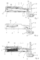
- the second swivel wing S2 is - as on is best seen in Fig. 8 - in sections in the form of a U-profile educated.
- the U-profile has a profile base 1 and two of them extending leg 2.
- a slot 3 is provided in each of the legs 2.
- the slot 3 describes the section of a circular arc with a radius R of 88 mm with respect a center line.
- the slot 3 is about 5 mm wide.
- a connecting piece designed as a metal strip 4 points to a second one End E2 two first bolts 5.
- Each of the first bolts 5 passes through one Slot 3.
- At the first end E1 is the metal strip 4 by means of another Bolt 6 pivotally attached to the first pivot wing S1.
- the other Bolt 6 is on the first swivel wing S1 in a web 7 formed thereon added.
- the bolt 6 is in the Metal strip 4 arranged in an elongated hole. This slot is in the metal tape 4 introduced. As a result, the hinge runs straight Movement out.
- the first swivel wing S1 has a further web 8 on the terminal is appropriate.
- the first swivel wing S1 is with the second swivel wing S2 pivotally connected by means of a second pin 9.
- the second bolt 9 is on the second swivel wing S2 at the end of a U-profile extending step-shaped paragraph 10 held.
- a tension spring 11 is on a bridge spanning a recess 12 mounted.
- the recess 12 is in one of the profile bottom 1 extending rear wall 13 connected to the two legs 2 intended.
- the other end of the tension spring 11 is approximately centered on the metal strip 4 appropriate.
- Bends 14 extending from the legs 2 can with threaded holes 15 for fastening the second swivel wing S2 be provided.
- the first S1 and the second swivel wing S2 can be made of plastic or Be made of metal.
- the second swivel wing S2 is usually in a suitable one Recess of a bottom of a piece of furniture attached. You can do this Engage screws in the threaded holes 15.
- the special design of the second swivel wing S2 with the inside sliding metal band 4 enables a particularly low overall height of the second swivel wing S2.
- the overall height is here by the height of the Leg 2 given.
- the second swivel wing S2 can thus advantageously in a bottom recess of a piece of furniture be included.
Abstract
Description
Die Erfindung betrifft ein Scharnier, insbesondere für Möbel.The invention relates to a hinge, in particular for furniture.
Nach dem Stand der Technik werden zur Anbringung von horizontal verschwenkbaren Klappen an Möbeln Scharnierbänder herkömmlicher Bauart verwendet. Um die Klappe im geöffneten Zustand in einer vorgegebenen Lage, z.B. in der horizontalen Lage, zu halten, sind zusätzliche Mittel zur Begrenzung des Schwenkwegs vorgesehen. Dabei handelt es sich z.B. um mit einem Anschlag versehene Stäbe, die einerseits an der Klappe schwenkbar angebracht und andererseits am Schrank in einer Führung verschiebbar aufgenommen sind. Sobald der Anschlag mit der Führung in Anlage kommt, wird eine weitere Schwenkbewegung der Klappe unterbunden. Die Klappe wird in einer vorgegebenen Lage gehalten.According to the state of the art are used for horizontal mounting hinged flaps on furniture hinge straps of conventional design used. To open the flap in a predetermined position, e.g. to keep in the horizontal position are additional means of limitation of the swivel path provided. This is e.g. around with one Stop provided rods that can be swiveled on the flap attached and on the other hand slidable on the cabinet in a guide are included. As soon as the stop comes into contact with the guide, further pivoting movement of the flap is prevented. The flap will held in a predetermined position.
Die bekannte Anordnung besteht aus mehreren Teilen, deren Herstellung und Montage aufwendig ist.The known arrangement consists of several parts, their manufacture and Assembly is complex.
Aufgabe der Erfindung ist es, ein Scharnier mit einem begrenzten Schwenkweg zu schaffen, das einfach aufgebaut und montagefreundlich ist.The object of the invention is to provide a hinge with a limited swivel path to create that is simple and easy to assemble.
Diese Aufgabe wird durch die Merkmale des Anspruchs 1 gelöst. Zweckmäßige
Ausgestaltungen ergeben sich aus den Merkmalen der Ansprüche 2 bis 14. This object is solved by the features of
Nach Maßgabe der Erfindung ist ein Scharnier, insbesondere für Möbel, vorgesehen, wobei ein erster Scharnierflügel schwenkbar mit einem zweiten Scharnierflügel verbunden und zur Begrenzung des Schwenkwegs ein Verbindungsstück vorgesehen ist, dessen erstes Ende schwenkbar am ersten Schwenkflügel befestigt und dessen zweites Ende verschiebbar entlang eines begrenzten Wegs am zweiten Schwenkflügel geführt ist. - Das Scharnier ist einfach aufgebaut. Die Montage einer besonderen Vorrichtung zur Begrenzung des Schwenkwegs ist nicht erforderlich.According to the invention, a hinge, especially for furniture, provided, a first hinge wing pivotable with a second Hinge wing connected and to limit the swivel path Connection piece is provided, the first end pivotable on the first Swivel wing attached and the second end slidably along one limited path is guided on the second swivel wing. - The hinge is simply set up. Installation of a special limitation device the swivel path is not necessary.
Vorteilhafterweise ist der zweite Schwenkflügel nach Art eines U-Profils ausgebildet. Das ermöglicht eine besonders flache Bauhöhe des zweiten Schwenkflügels, indem das Verbindungsstück zwischen den Schenkeln des U-Profils untergebracht ist.The second swivel wing is advantageously in the manner of a U-profile educated. This enables a particularly flat height of the second Swivel wing, adding the connector between the legs of the U-profile is housed.
Nach einer Ausgestaltungsform sind in den Schenkeln des U-Profils in einander gegenüberliegender Anordnung schlitzartige Ausnehmungen vorgesehen. Eine gedachte Mittellinie jeder schlitzartigen Ausnehmung kann dabei einen Abschnitt einer Kreiskurve beschreiben, wobei der Radius der Mittellinie 50 bis 100 mm, vorzugsweise 82 bis 94 mm, beträgt. Die Breite der schlitzartigen Ausnehmungen beträgt zweckmäßigerweise etwa 5 mm. Am zweiten Ende ist mindestens ein quer zur Längsseite des Verbindungsstücks verlaufender erster Bolzen vorgesehen. Es können aber auch zwei erste Bolzen vorgesehen sein. Der/die erste/n Bolzen durchgreifen die schlitzartigen Ausnehmungen.According to an embodiment are in the legs of the U-profile mutually opposite arrangement slot-like recesses intended. An imaginary center line of each slot-like recess can describe a section of a circular curve, the radius of the Center line is 50 to 100 mm, preferably 82 to 94 mm. The width of the slot-like recesses is advantageously about 5 mm. At the second end is at least one transverse to the long side of the connector extending first bolt provided. But it can also be two first Bolts may be provided. The first bolt (s) reach through the slot-like Recesses.
Die vorgenannten Merkmale tragen weiter zu einer besonders flachen Bauhöhe
des zweiten Schwenkflügels bei. Sie gewährleisten, dass das
Verbindungsstück unabhängig von der Stellung des ersten Schwenkflügels
nicht über die im wesentlichen durch die Höhe der Schenkel gegebene
Bauhöhe des zweiten Schwenkflügels hinaus sich bewegt.
Von herstellungstechnischem Vorteil ist es. dass das erste Ende am ersten
Schwenkflügel an einer sich davon erstreckenden stegartigen Erhebung
angebracht ist. Das erste Ende kann daran mittels eines weiteren Bolzens
schwenkbar angebracht sein. Zweckmäßigerweise weist der zweite
Scharnierflügel am dem ersten Scharnierflügel zugewandten Ende einen
stufenartigen Absatz auf. Vorteilhafterweise ist der erste Scharnierflügel mittels
eines zweiten Bolzens schwenkbar am Ende des stufenartigen Absatzes
angebracht. Das bewirkt, dass bei einem Verschwenken des ersten
Schwenkflügels das erste Ende auf einem Radius bewegt wird, der eine
besonders geringe vertikale Auslenkung des Verbindungsstücks hervorruft.The aforementioned features further contribute to a particularly flat overall height of the second swivel wing. They ensure that, regardless of the position of the first swivel wing, the connecting piece does not move beyond the structural height of the second swivel wing, which is essentially given by the height of the legs.
It is a manufacturing advantage. that the first end is attached to the first swivel wing on a web-like elevation extending therefrom. The first end can be pivotally attached to it by means of a further bolt. The second hinge wing expediently has a step-like shoulder at the end facing the first hinge wing. Advantageously, the first hinge wing is pivotally attached to the end of the step-like heel by means of a second bolt. This has the effect that when the first swivel wing is pivoted, the first end is moved on a radius which causes a particularly small vertical deflection of the connecting piece.
Nach einem weiteren Ausgestaltungsmerkmal ist eine am freien Ende des zweiten Scharnierflügels angebrachte Zugfeder mit dem Verbindungsstück verbunden. Dadurch wird eine selbsttätige Rückstellung des ersten Scharnierflügels in eine Ausgangsstellung bewirkt. Je nach Gewicht der am ersten Scharnierflügel angebrachten Platte ist aber auch eine Öffnungsbewegung mit zunehmender Dämpfung einstellbar.According to a further design feature, one is at the free end of the second hinge wing attached tension spring with the connector connected. This will automatically reset the first Hinge wing causes in a starting position. Depending on the weight of the the first hinge wing attached plate is also a Opening movement adjustable with increasing damping.
Es kann zusätzlich im zweiten Scharnierflügel eine mit dem Verbindungsstück zusammenwirkende Rastvorrichtung vorgesehen sein, mittels derer der erste Scharnierflügel an einem bestimmten vorgegebenen Ort des Schwenkwegs verrastbar ist. Ferner kann im zweiten Schwenkflügel eine Vorrichtung aufgenommen sein, die bei Erreichen eines vorgegebenen Schwenkwinkels der Schwenkbewegung einen zusätzlichen Widerstand entgegensetzt. Dadurch kann das Erreichen eines bestimmten Schwenkwinkels angezeigt werden. Bei Überwindung des Widerstands kann zweckmäßigerweise zusätzlich ein Geräusch verursacht werden. das dem Benutzer zusätzlich das Überschreiten des vorgegebenen Schwenkwinkels akustisch anzeigt.There can also be one with the connecting piece in the second hinge wing cooperating locking device can be provided, by means of which the first Hinge wing at a certain predetermined location of the swivel path can be locked. Furthermore, a device can be in the second swivel wing be included, when reaching a predetermined swivel angle Panning movement provides additional resistance. Thereby the reaching of a certain swivel angle can be displayed. At Overcoming the resistance can expediently additionally Noise caused. which the user also exceeds of the specified swivel angle acoustically.
Zur Montage des zweiten Scharnierflügels ist es zweckmäßig, dass an den Kanten der Schenkel aufeinander zuweisende Umbiegungen vorgesehen sind, die jeweils einen Durchbruch zur Befestigung des zweiten Scharnierflügels aufweisen. Der Durchbruch kann mit einem Gewinde versehen sein. Das Verbindungsstück ist zweckmäßigerweise ein Metallband.To assemble the second hinge wing, it is appropriate that the Edges of the legs facing one another are provided, each have a breakthrough for attaching the second hinge wing exhibit. The breakthrough can be threaded. The The connecting piece is expediently a metal band.
Nachfolgend wird anhand der Zeichnung ein Ausführungsbeispiel der
Erfindung beschrieben. Hierin zeigen:
In den Fig. 1 bis 8 ist ein erster Schwenkflügel S1 und ein zweiter
Schwenkflügel mit S2 bezeichnet. Der zweite Schwenkflügel S2 ist - wie am
besten aus Fig. 8 ersichtlich ist - abschnittsweise in Form eines U-Profils
ausgebildet. Das U-Profil weist einen Profilboden 1 und zwei davon sich
erstreckende Schenkel 2 auf.1 to 8 is a first pivot wing S1 and a second
Swivel wing labeled S2. The second swivel wing S2 is - as on
is best seen in Fig. 8 - in sections in the form of a U-profile
educated. The U-profile has a
In jedem der Schenkel 2 ist ein Schlitz 3 vorgesehen. Der Schlitz 3 beschreibt
den Abschnitt eines Kreisbogens mit einem Radius R von 88 mm bezüglich
einer Mittellinie. Der Schlitz 3 ist etwa 5 mm breit.A
Ein als Metallband 4 ausgebildetes Verbindungsstück weist an einem zweiten
Ende E2 zwei erste Bolzen 5 auf. Jeder der ersten Bolzen 5 durchgreift einen
Schlitz 3. Am ersten Ende E1 ist das Metallband 4 mittels eines weiteren
Bolzens 6 schwenkbar am ersten Schwenkflügel S1 angebracht. Der weitere
Bolzen 6 ist am ersten Schwenkflügel S1 in einem daran angeformten Steg 7
aufgenommen.A connecting piece designed as a
In einer vorteilhaften Ausgestaltung der Erfindung ist der Bolzen 6 im
Metallband 4 in einem Langloch angeordnet. Dieses Langloch ist im
metallband 4 eingebracht. Hierdurch führt das Scharnier eine gerade
Bewegung aus.In an advantageous embodiment of the invention, the
Der erste Schwenkflügel S1 weist einen weiteren Steg 8 auf der endständig
angebracht ist. Der erste Schwenkflügel S1 ist mit dem zweiten Schwenkflügel
S2 mittels eines zweiten Bolzens 9 schwenkbar verbunden.The first swivel wing S1 has a
Der zweite Bolzen 9 ist am zweiten Schwenkflügel S2 am Ende eines sich vom
U-Profil erstreckenden stufenförmigen Absatzes 10 gehalten. The
Eine Zugfeder 11 ist an einer eine Ausnehmung 12 überspannenden Brücke
eingehängt. Die Ausnehmung 12 ist in einem vom Profilboden 1 sich
erstreckenden und mit den beiden Schenkeln 2 verbundenen Rückwand 13
vorgesehen. Das andere Ende der Zugfeder 11 ist etwa mittig am Metallband 4
angebracht. Von den Schenkeln 2 sich erstreckende Umbiegungen 14 können
mit Gewindebohrungen 15 zur Befestigung des zweiten Schwenkflügels S2
vorgesehen sein.A
Der erste S1 und der zweite Schwenkflügel S2 können aus Kunststoff oder Metall hergestellt sein.The first S1 and the second swivel wing S2 can be made of plastic or Be made of metal.
Die Funktion des Scharniers ist folgende:The function of the hinge is as follows:
Der zweite Schwenkflügel S2 ist üblicherweise in einer geeigneten Ausnehmung eines Bodens eines Möbelstücks befestigt. Dazu können Schrauben in die Gewindebohrungen 15 eingreifen.The second swivel wing S2 is usually in a suitable one Recess of a bottom of a piece of furniture attached. You can do this Engage screws in the threaded holes 15.
Am ersten Schwenkflügel S1 ist üblicherweise eine (hier nicht dargestellte) Klappe ebenfalls mittels Schrauben befestigt.On the first swivel wing S1 there is usually a (not shown here) Flap also fastened with screws.
Bei einer Schwenkbewegung des ersten Schwenkflügels S1 aus der hier
gezeigten Ausgangsstellung in eine horizontale Stellung wird das Metallband 4
aus dem U-Profil herausgezogen. Die ersten Bolzen 5 sind gleitend in den
Schlitzen 3 geführt. Das zweite Ende E2 des Metallbands wird beim
Herausziehen aus dem U-Profil entlang dem Kreisbogen geführt. Dadurch wird
bewirkt, dass das Metallband 4 nicht an den Profilboden 1 anstößt. Sobald die
ersten Bolzen 5 an den Enden der Schlitze 3 anliegen, ist eine weitere
Schwenkbewegung nicht mehr möglich. Die Schwenkbewegung wird also durch
die Länge der Schlitze 3 begrenzt. Die Schwenkbewegung in die horizontale
Stellung erfolgt entgegen der zunehmenden Rückstellkraft der Zugfeder 11.With a pivoting movement of the first pivoting wing S1 from here
Starting position shown in a horizontal position, the metal strip 4th
pulled out of the U-profile. The
Die besondere Ausbildung des zweiten Schwenkflügels S2 mit dem darin
gleitend geführten Metallband 4 ermöglicht eine besonders geringe Bauhöhe
des zweiten Schwenkflügels S2. Die Bauhöhe ist hier durch die Höhe der
Schenkel 2 gegeben. Die zweiten Schwenkflügel S2 können somit
vorteilhafterweise in einer bodenseitigen Ausnehmung eines Möbelstücks
aufgenommen werden. The special design of the second swivel wing S2 with the inside
sliding
- 11
- ProfilbodenProfile floor
- 22nd
- Schenkelleg
- 33rd
- Schlitzslot
- 44th
- Metallband (Verbindungsstück)Metal band (connector)
- 55
- erster Bolzenfirst bolt
- 66
- weiterer Bolzenanother bolt
- 77
- Stegweb
- 88th
- weiterer Steganother footbridge
- 99
- zweite Bolzensecond bolt
- 1010th
- Absatzparagraph
- 1111
- ZugfederTension spring
- 1212th
- AusnehmungRecess
- 1313
- RückwandBack wall
- 1414
- UmbiegungBend
- 1515
- GewindebohrungTapped hole
- S1S1
- erster Schwenkflügelfirst swivel wing
- S2S2
- zweiter Schwenkflügelsecond swivel wing
- E1E1
- erstes Endefirst end
- E2E2
- zweites Endesecond end
- RR
- Radiusradius
Claims (14)
Applications Claiming Priority (2)
| Application Number | Priority Date | Filing Date | Title |
|---|---|---|---|
| DE19922006 | 1999-05-12 | ||
| DE19922006A DE19922006A1 (en) | 1999-05-12 | 1999-05-12 | hinge |
Publications (3)
| Publication Number | Publication Date |
|---|---|
| EP1052359A2 true EP1052359A2 (en) | 2000-11-15 |
| EP1052359A3 EP1052359A3 (en) | 2002-04-03 |
| EP1052359B1 EP1052359B1 (en) | 2004-07-21 |
Family
ID=7907909
Family Applications (1)
| Application Number | Title | Priority Date | Filing Date |
|---|---|---|---|
| EP00109406A Expired - Lifetime EP1052359B1 (en) | 1999-05-12 | 2000-05-03 | Hinge |
Country Status (2)
| Country | Link |
|---|---|
| EP (1) | EP1052359B1 (en) |
| DE (2) | DE19922006A1 (en) |
Cited By (1)
| Publication number | Priority date | Publication date | Assignee | Title |
|---|---|---|---|---|
| EP1439277A1 (en) * | 2003-01-16 | 2004-07-21 | Grundig Aktiengesellschaft i. Ins. | Hinge |
Families Citing this family (3)
| Publication number | Priority date | Publication date | Assignee | Title |
|---|---|---|---|---|
| DE10141115B4 (en) * | 2001-08-22 | 2009-10-22 | Grundig Multimedia B.V. | hinge |
| DE10254375C1 (en) * | 2002-04-30 | 2003-11-13 | Zimmer Guenther | Furniture component pivot movement damping arrangement, has pivot joint with damping unit to slow movement of component near end position and hinge lever to engage piston-operating unit when component approaches end position |
| DE10260480A1 (en) | 2002-12-21 | 2004-07-01 | Deere & Company, Moline | Drive system of a self-propelled work machine |
Citations (5)
| Publication number | Priority date | Publication date | Assignee | Title |
|---|---|---|---|---|
| US3388417A (en) * | 1965-06-28 | 1968-06-18 | Gen Motors Corp | Closure hinge |
| DE1906095A1 (en) * | 1968-02-12 | 1969-08-21 | Jllinois Tool Works Inc | Door control |
| US3748689A (en) * | 1970-10-06 | 1973-07-31 | H Grunert | Adjustable hinge for butt-closing doors |
| FR2304257A7 (en) * | 1975-03-08 | 1976-10-08 | Bosch Siemens Hausgeraete | Domestic dishwasher door hinge - has cantilever arm forming opening stop and spring assisting door closure |
| GB2079361A (en) * | 1980-07-01 | 1982-01-20 | Devilca Fb Sa | Hinges |
-
1999
- 1999-05-12 DE DE19922006A patent/DE19922006A1/en not_active Withdrawn
-
2000
- 2000-05-03 EP EP00109406A patent/EP1052359B1/en not_active Expired - Lifetime
- 2000-05-03 DE DE50007103T patent/DE50007103D1/en not_active Expired - Lifetime
Patent Citations (5)
| Publication number | Priority date | Publication date | Assignee | Title |
|---|---|---|---|---|
| US3388417A (en) * | 1965-06-28 | 1968-06-18 | Gen Motors Corp | Closure hinge |
| DE1906095A1 (en) * | 1968-02-12 | 1969-08-21 | Jllinois Tool Works Inc | Door control |
| US3748689A (en) * | 1970-10-06 | 1973-07-31 | H Grunert | Adjustable hinge for butt-closing doors |
| FR2304257A7 (en) * | 1975-03-08 | 1976-10-08 | Bosch Siemens Hausgeraete | Domestic dishwasher door hinge - has cantilever arm forming opening stop and spring assisting door closure |
| GB2079361A (en) * | 1980-07-01 | 1982-01-20 | Devilca Fb Sa | Hinges |
Cited By (1)
| Publication number | Priority date | Publication date | Assignee | Title |
|---|---|---|---|---|
| EP1439277A1 (en) * | 2003-01-16 | 2004-07-21 | Grundig Aktiengesellschaft i. Ins. | Hinge |
Also Published As
| Publication number | Publication date |
|---|---|
| EP1052359A3 (en) | 2002-04-03 |
| DE19922006A1 (en) | 2000-11-16 |
| EP1052359B1 (en) | 2004-07-21 |
| DE50007103D1 (en) | 2004-08-26 |
Similar Documents
| Publication | Publication Date | Title |
|---|---|---|
| EP3303859B1 (en) | Fastening element | |
| EP2566729B1 (en) | Wiper motor with a decoupling element | |
| EP0569818B1 (en) | Hinge | |
| EP1052359A2 (en) | Hinge | |
| DE3809966A1 (en) | DEVICE FOR LOCKING THE LIFTED WIPER ARM OF A WIPER | |
| WO2007076912A1 (en) | Mechanical door stop for doors, in particular vehicle doors | |
| DE102010037940A1 (en) | Sliding door roller guide and arrangement of a sliding door roller guide on a piece of furniture | |
| EP0495233B1 (en) | Check for a window, door or the like | |
| EP2162591B1 (en) | Guide arrangement for a sliding element | |
| DE2443866A1 (en) | DEVICE FOR SECURING THE POSITION OF THE EXTENDING ARM OF EXHIBITION DEVICES FOR WINDOWS, DOORS OR THE LIKE. | |
| DE4304456A1 (en) | Sliding rail for car seat with end stop - has spring stop formed by inner and outer box-sections joined by elastic rib and with overlapping flanges | |
| EP0478639A1 (en) | Hinge. | |
| DE19702863B4 (en) | Hinge for a wing part, in particular a door or window wing | |
| DE4400249C1 (en) | Wall installation duct for electrical installation facilities | |
| EP1707075B1 (en) | Folding table and fitting for folding table | |
| DE7713654U1 (en) | HINGE FOR A WINDOW, A DOOR OR DGL. | |
| DE19505281C2 (en) | conductor arrangement | |
| EP0730836B1 (en) | Curtain glider | |
| DE102017121385A1 (en) | Mirrors and drawer | |
| DE202004000405U1 (en) | Display device for a tilt and turn sash of a window or a door | |
| DE19517941C2 (en) | hinge | |
| DE102010028603B3 (en) | Fitting part for attachment to a C-shaped fitting part | |
| DE3923450C2 (en) | Furniture hinge | |
| EP3623558B1 (en) | Lid fitting for swingable mounting of a lid to a furniture unit | |
| EP3359763B1 (en) | Hinge for a folding flap |
Legal Events
| Date | Code | Title | Description |
|---|---|---|---|
| PUAI | Public reference made under article 153(3) epc to a published international application that has entered the european phase |
Free format text: ORIGINAL CODE: 0009012 |
|
| AK | Designated contracting states |
Kind code of ref document: A2 Designated state(s): AT BE CH CY DE DK ES FI FR GB GR IE IT LI LU MC NL PT SE Kind code of ref document: A2 Designated state(s): DE FR GB IT |
|
| AX | Request for extension of the european patent |
Free format text: AL;LT;LV;MK;RO;SI |
|
| RAP1 | Party data changed (applicant data changed or rights of an application transferred) |
Owner name: GRUNDIG AKTIENGESELLSCHAFT |
|
| PUAL | Search report despatched |
Free format text: ORIGINAL CODE: 0009013 |
|
| AK | Designated contracting states |
Kind code of ref document: A3 Designated state(s): AT BE CH CY DE DK ES FI FR GB GR IE IT LI LU MC NL PT SE |
|
| AX | Request for extension of the european patent |
Free format text: AL;LT;LV;MK;RO;SI |
|
| 17P | Request for examination filed |
Effective date: 20020914 |
|
| AKX | Designation fees paid |
Free format text: DE FR GB IT |
|
| 17Q | First examination report despatched |
Effective date: 20021212 |
|
| GRAP | Despatch of communication of intention to grant a patent |
Free format text: ORIGINAL CODE: EPIDOSNIGR1 |
|
| GRAS | Grant fee paid |
Free format text: ORIGINAL CODE: EPIDOSNIGR3 |
|
| GRAA | (expected) grant |
Free format text: ORIGINAL CODE: 0009210 |
|
| AK | Designated contracting states |
Kind code of ref document: B1 Designated state(s): DE FR GB IT |
|
| REG | Reference to a national code |
Ref country code: GB Ref legal event code: FG4D Free format text: NOT ENGLISH |
|
| RAP2 | Party data changed (patent owner data changed or rights of a patent transferred) |
Owner name: GRUNDIG MULTIMEDIA B.V. |
|
| REG | Reference to a national code |
Ref country code: IE Ref legal event code: FG4D Free format text: GERMAN |
|
| REF | Corresponds to: |
Ref document number: 50007103 Country of ref document: DE Date of ref document: 20040826 Kind code of ref document: P |
|
| GBT | Gb: translation of ep patent filed (gb section 77(6)(a)/1977) |
Effective date: 20040818 |
|
| ET | Fr: translation filed | ||
| PLBE | No opposition filed within time limit |
Free format text: ORIGINAL CODE: 0009261 |
|
| STAA | Information on the status of an ep patent application or granted ep patent |
Free format text: STATUS: NO OPPOSITION FILED WITHIN TIME LIMIT |
|
| 26N | No opposition filed |
Effective date: 20050422 |
|
| REG | Reference to a national code |
Ref country code: FR Ref legal event code: PLFP Year of fee payment: 17 |
|
| REG | Reference to a national code |
Ref country code: FR Ref legal event code: PLFP Year of fee payment: 18 |
|
| REG | Reference to a national code |
Ref country code: FR Ref legal event code: PLFP Year of fee payment: 19 |
|
| PGFP | Annual fee paid to national office [announced via postgrant information from national office to epo] |
Ref country code: DE Payment date: 20190529 Year of fee payment: 20 Ref country code: IT Payment date: 20190531 Year of fee payment: 20 |
|
| PGFP | Annual fee paid to national office [announced via postgrant information from national office to epo] |
Ref country code: FR Payment date: 20190524 Year of fee payment: 20 |
|
| PGFP | Annual fee paid to national office [announced via postgrant information from national office to epo] |
Ref country code: GB Payment date: 20190524 Year of fee payment: 20 |
|
| REG | Reference to a national code |
Ref country code: DE Ref legal event code: R071 Ref document number: 50007103 Country of ref document: DE |
|
| REG | Reference to a national code |
Ref country code: GB Ref legal event code: PE20 Expiry date: 20200502 |
|
| PG25 | Lapsed in a contracting state [announced via postgrant information from national office to epo] |
Ref country code: GB Free format text: LAPSE BECAUSE OF EXPIRATION OF PROTECTION Effective date: 20200502 |