EP1052169A2 - Unterbodenstruktur einer Rumpfzelle eines Luftfahrzeuges - Google Patents
Unterbodenstruktur einer Rumpfzelle eines Luftfahrzeuges Download PDFInfo
- Publication number
- EP1052169A2 EP1052169A2 EP00109111A EP00109111A EP1052169A2 EP 1052169 A2 EP1052169 A2 EP 1052169A2 EP 00109111 A EP00109111 A EP 00109111A EP 00109111 A EP00109111 A EP 00109111A EP 1052169 A2 EP1052169 A2 EP 1052169A2
- Authority
- EP
- European Patent Office
- Prior art keywords
- underbody structure
- cross
- longitudinal
- section
- structure according
- Prior art date
- Legal status (The legal status is an assumption and is not a legal conclusion. Google has not performed a legal analysis and makes no representation as to the accuracy of the status listed.)
- Granted
Links
- 239000003351 stiffener Substances 0.000 claims abstract description 6
- 238000010276 construction Methods 0.000 abstract description 15
- NTHWMYGWWRZVTN-UHFFFAOYSA-N sodium silicate Chemical compound [Na+].[Na+].[O-][Si]([O-])=O NTHWMYGWWRZVTN-UHFFFAOYSA-N 0.000 description 15
- 239000002131 composite material Substances 0.000 description 10
- 238000010521 absorption reaction Methods 0.000 description 7
- 239000000835 fiber Substances 0.000 description 7
- 239000000463 material Substances 0.000 description 7
- 238000004026 adhesive bonding Methods 0.000 description 5
- 239000000243 solution Substances 0.000 description 4
- 239000000969 carrier Substances 0.000 description 2
- 238000011156 evaluation Methods 0.000 description 2
- 238000004519 manufacturing process Methods 0.000 description 2
- 238000005253 cladding Methods 0.000 description 1
- 238000004049 embossing Methods 0.000 description 1
- 238000005265 energy consumption Methods 0.000 description 1
- 238000009434 installation Methods 0.000 description 1
- 230000010354 integration Effects 0.000 description 1
- 239000002184 metal Substances 0.000 description 1
- 230000035515 penetration Effects 0.000 description 1
- 230000004584 weight gain Effects 0.000 description 1
- 235000019786 weight gain Nutrition 0.000 description 1
Images


Classifications
-
- B—PERFORMING OPERATIONS; TRANSPORTING
- B64—AIRCRAFT; AVIATION; COSMONAUTICS
- B64C—AEROPLANES; HELICOPTERS
- B64C1/00—Fuselages; Constructional features common to fuselages, wings, stabilising surfaces or the like
- B64C1/06—Frames; Stringers; Longerons ; Fuselage sections
- B64C1/061—Frames
- B64C1/062—Frames specially adapted to absorb crash loads
-
- B—PERFORMING OPERATIONS; TRANSPORTING
- B64—AIRCRAFT; AVIATION; COSMONAUTICS
- B64C—AEROPLANES; HELICOPTERS
- B64C1/00—Fuselages; Constructional features common to fuselages, wings, stabilising surfaces or the like
- B64C1/18—Floors
Definitions
- the invention relates to an underbody structure of a fuselage cell of an aircraft, in particular a helicopter, the underbody structure with the floor and the outer fuselage shell is connected, consisting of interconnected longitudinal and Cross beams, with structural elements and stiffeners being arranged on the beams.
- Aircraft construction pays appropriate attention to the safety design of a fuselage cell in the event of an impact with its lower fuselage area.
- the underbody structure within a fuselage cell plays an important role in the associated safety concept.
- the underbody structure is connected to the floor, which consists of at least one floor slab, and the outer fuselage shell. Structures such as seats are arranged on the base plate.
- the underbody structure Upon impact of a fuselage cell with its lower fuselage surface, the underbody structure should absorb a substantial part of the kinetic energy of the impact, so that the protection of pilots and passengers is improved.
- tank containers are often arranged within the underbody structure, they must have the possibility of preferably escaping laterally in the event of an impact, the underbody structure should not injure the tank container as far as possible.
- the lower cladding (outer fuselage shell) of the fuselage cell should transmit the impact energy to the underbody structure without breaking as far as possible.
- the underbody structure known in the prior art is based on the assumption that the impact for the underbody structure represents a predominantly axial load, that is to say corresponds to a vertical impact. It is therefore known in the prior art that the columnar structural element, for example a circular cylindrical shell made of fiber composite material, has the best peak-to-power ratio in the event of such an impact, while at the same time having the highest specific energy consumption. Because of this, column-shaped structural elements are often used in the underbody structure.
- the columnar shape includes the circular cross-section but also the polyhedral shape.
- Fiber composite or metal construction methods are customary, with columnar structural elements being integrated in one carrier and several, parallel positioned carriers forming the underbody structure. Since the columns or cylinders are very sensitive to non-axial stress, they also require so-called trigger concepts that correspond to defined predetermined breaking points in order to reduce the force peak occurring in the event of an impact and to achieve a controlled fracture mechanism (direction of fracture). Controlled fracture mechanics predict how and when the body deforms when subjected to the load. The impact behavior of an underbody structure is largely determined by the absorption capacity and the controlled fracture mechanics. [1] DE 37 44 349 A1, Figure 7 describes the bottom of a helicopter in which corrugated, plate-shaped structural elements are arranged.
- the underbody structure shown in [2] has the disadvantage that it absorbs energy Structural elements are formed only at the points of intersection of the frame. So that's the Use of energy-absorbing structural elements is very limited. Such columnar structural elements, whether cylindrical or as a polyhedron, are sensitive to side loads.
- the object of the invention is to further improve the impact behavior of the underbody structure inserted into a fuselage cell, taking into account a lightweight construction.
- the object is achieved according to the characterizing features of claim 1.
- the longitudinal members and cross members of the underbody structure have a trapezoidal cross-section. This is achieved when the parallel, larger standing side of the trapezoidal cross section opposite a rear side is open.
- the longitudinal beams and cross beams can advantageously be arranged to form a grating. The connection of two beams results in an advantageous cone structure at the point of intersection of the beams.
- the beams can be dimensioned with the aid of wall thickness and a layer structure known in the case of fiber composite construction.
- the shoulder side of a beam can be equipped with an optimal flank angle of 10 ° to 25 ° depending on the load direction and load type.
- the slanted shoulder sides of a strap are stiffened.
- Cones with rectangular cross sections ie truncated pyramids
- the entire grating thus consists of inserted cones with a rectangular cross-section.
- the connections between the trapezoidal supports and the cones are advantageously made by overlap gluing of the folds. However, other types of connection are also possible.
- the truncated pyramids fit positively into the contour of a wearer. Beam and truncated pyramid advantageously have a flank angle of 10 ° to 25 °.
- the open stand side of a carrier can be covered with a plate to be fixed, for example after inserting the cones.
- the optimal underbody structure results from longitudinal and cross members and the cones inserted into them.
- the underbody structure according to the invention has the advantage that both axial loads and side loads can be safely absorbed in the event of an impact. Previous trigger devices are not necessary. Since the direction of fracture of the underbody structure according to the invention is predefined inwards (interior of the trapezoidal cross-section), the safety behavior improves since penetration of broken material into tank vessels embedded between the underbody structure is hardly possible. The underbody structure has a very good energy absorption with a low weight, so that demands for a lightweight construction have to be met. Likewise, all forces not caused by impact can be safely transmitted through the grating.
- the fuselage of an aircraft consists of at least one fuselage cell. Are several if such fuselage cells are required, they are connected one after the other in a modular manner.
- the skeletal structure of a fuselage cell is usually covered by an outer skin Shell segments, surrounded.
- the fuselage cell is also designed so that it Payloads (crew, passengers, cargo) can take. To do this, floors required, which are carried by the fuselage.
- the underbody structure is directly connected to a floor. It not only improves the load-bearing capacity of the Floor, but also improves stability and fracture behavior in the event of impact Fuselage from low altitude.
- the safety behavior of an underbody structure when Impact is largely determined by the assets, parts by the kinetic Effectively absorb impact energy and adhere to a defined breaking direction.
- the longitudinal and transverse beams are equipped with a trapezoidal cross section.
- longitudinal members and transverse members oriented transversely thereto are arranged to form an underbody structure.
- the longitudinal and transverse beams are connected to each other at the crossing points.
- the trapezoidal cross section of a carrier is achieved by all sides of the trapezoid being formed by the carrier.
- the carrier is hollow.
- the large number of longitudinal and cross members that are connected to each other form a grating put together.
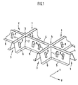
- FIG. 1 An economically efficient variant in the design of the trapezoidal cross section of the carrier is achieved in accordance with FIG. 1 if the parallel, larger stand side opposite the rear side 4 is open, ie is not present.
- the three sides are formed by the back side 4 and the two shoulder sides 41, 42, each shoulder side being supported at an angle. This creates a profile beam, the three sides of which are arranged in a trapezoidal shape. They form the trapezoidal cross section 3.
- the underbody structure is fastened to the floor (for example by gluing) and connected to the outer casing of the fuselage cell.
- the floor consists of at least one floor slab.
- Each carrier can be equipped with a fold 6.
- the two sloping shoulder sides are stiffened, for example by wave-shaped embossing or by spaced stiffeners in the material. Bracing of the shoulder side can also be achieved by designing the shoulder side in a sandwich construction.
- Fig. 1 shows the stiffening of the shoulder side in the material. The bracing corresponds to a bulge in the material.
- the longitudinal beams 1 and the cross beams 2 are arranged like a grating and form crossing points 5.
- FIG. 1 shows a section of the grating.
- the longitudinal and transverse beams form a seam 7 at their common points of contact.
- the crossing angle ⁇ is advantageously essentially 90 °. A uniform shape of the crossing point 5 is thus achieved.
- Such a design corresponds to an optimal absorption of forces and enables inexpensive production.
- FIG. 1 a shows a top view of such an intersection point 5, formed by longitudinal beams 1 and cross beams 2.
- the sections AA and BB illustrate the advantageous trapezoidal cross section 3 of a longitudinal and cross beam.
- the trapezoidal cross section is formed by the larger stand side 40 opposite a rear side 4 being open, ie not being present.
- the flank angle ⁇ represents the steepness of an oblique shoulder side 41, 42 of the trapezoid in relation to the perpendicular L.
- the opening angle ⁇ describes the angle which the two oblique shoulder sides 41, 42 of the trapezoidal cross section enclose. It adds up from the two flank angles ⁇ i .
- the carriers 1, 2 have folds 6 arranged in the ends of the oblique shoulder walls, in the plane of the standing side 40, which lead away from the trapezoidal cross section. These folds 6 are used for fastening structural elements.
- a beam is dimensioned by the geometric dimensions of its three trapezoidal sides, the flank angle ⁇ , the wall thickness t and the material, fiber composite material advantageously being used. Other materials can also be used depending on the intended use.
- the walls of the longitudinal or cross member can advantageously be designed in the layer structure.
- the flank angles ⁇ i of the longitudinal and cross members can also be different.
- the trapezoidal cross-section of a longitudinal or cross member gives the underbody structure the advantage that both axial loads and side loads can be optimally absorbed as a result of an impact. It is not necessary to create additional trigger devices.
- This behavior of the carrier in the event of an impact can be further improved if structural elements in the form of a truncated pyramid 8 are inserted into the carrier 1, 2 and connected to the latter.
- FIG. 2 shows the top view of a truncated pyramid 8. Below that, the associated section CC is shown.
- the truncated pyramid 8 also called the cone, is inserted in such a way that two of the oblique, opposite pyramid walls are in positive contact with the oblique shoulder walls of a wearer.
- the truncated pyramid 8 is consequently inserted with its top surface 40 up to the stop in the opening angle ⁇ of the carrier.
- the opening angle ⁇ K of the cone should advantageously correspond essentially to the opening angle ⁇ of the carrier.
- the outer contour of the truncated pyramid 8 thus adapts to the contour of the carrier 1, 2. Since the truncated pyramid 8 is also equipped with folds 60, these come into contact with the folds 6 of the carrier 1, 2.
- the connection can be made by gluing (overlap gluing) or other types of connection.
- the truncated pyramid 8 advantageously corresponds to a cone whose larger of the two parallel surfaces is open. It is therefore hollow.
- the truncated pyramid 8 was found to be insensitive to deviations from the axial load direction.
- FIG. 3 shows a top view of a longitudinal member 1 and cross member 2 with inserted truncated pyramids 8.
- the number of these truncated pyramids 8 can be selected. An advantageously high absorption capacity of kinetic energy is achieved if one truncated pyramid 8 is arranged next to the other. Since the crossing point 5 between the longitudinal and transverse beams essentially also corresponds to a cone structure, no additional cone has to be inserted there.
- the grid-like arrangement of the trapezoidal longitudinal and cross members forms the underbody structure.
- the shoulder sides of the girders have stiffeners 9 or can alternatively be designed in a sandwich construction.
- the back sides 4 (corresponds to the smaller side of the two parallel sides of a trapezoid) are fastened to the floor and the edge of the underbody structure that comes into contact with the outer casing attached there.
- the direction of fracture is predefined inwards into the trapezoid or inwards into the truncated cone. It is thereby achieved that the material of the underbody does not damage the tank vessel located in between. All forces not caused by impact can also be safely transmitted through the grating.
- the underbody has a very good energy absorption with a low own load. It thus fulfills the requirements for a lightweight construction.
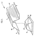
- Fig. 4 shows a short section of a carrier 1, 2 into which a cone, the truncated pyramid 8, is to be inserted.
- the cover side 40 of the truncated pyramid 8 is in abutment with the support side 4 of the support 1, 2.
- the cover side 40 is rectangular. Since the trapezoidal profile (FIG. 2, section CC) of the truncated pyramid 8 essentially corresponds in its dimension to the trapezoidal cross section (FIG. 1a, section AA or section BB) of the carrier 1, 2, the truncated pyramid is form-fitting in the carrier 1 , 2 inserted.
- the folds 60 of the truncated pyramid 8 running longitudinally to the support come to coincide with the folds 6 of the support.
- a connection of the folds makes sense by means of gluing.
- Further adjacent truncated pyramids 8 can be inserted in the longitudinal direction of the carrier 1, 2. In this case, adjacent truncated pyramids 8 can be mutually connected with the overlapping folds 60.
Landscapes
- Engineering & Computer Science (AREA)
- Mechanical Engineering (AREA)
- Aviation & Aerospace Engineering (AREA)
- Vibration Dampers (AREA)
- Body Structure For Vehicles (AREA)
Abstract
Description
Die im Stand der Technik bekannte Unterbodenstruktur geht von der Annahme aus, daß der Aufprall für die Unterbodenstruktur eine überwiegend axiale Belastung darstellt, also einem vertikalen Aufprall entspricht.
Es ist deshalb im Stand der Technik bekannt, daß das säulenförmige Strukturelement beispielsweise eine Kreiszylinderschale aus Faserverbund-Werkstoff im Fall eines solchen Aufpralls das beste Kraftspitzenverhältnis bei zugleich höchster spezifischer Energieaufnahme besitzt. Aufgrund dieses Sachverhaltes finden häufig säulenförmige Strukturelemente in der Unterbodenstruktur Verwendung. Die Säulenform umfaßt den kreisförmigen Querschnitt aber auch den polyederförmigen. Es sind Faserverbund- oder Metallbauweisen üblich, wobei säulenförmige Strukturelemente in einem Träger integriert sind und mehrere, parallel positionierte Träger die Unterbodenstruktur bilden. Da die Säulen bzw. Zylinder sehr empfindlich sind gegenüber nicht axialer Beanspruchung, benötigen sie zusätzlich sogenannte Trigger-Konzepte, daß entspricht definierten Sollbruchstellen, um die beim Aufprall auftretende Kraftspitze zu reduzieren und eine kontrollierte Bruchmechanik (Bruchrichtung) zu erzielen. Eine kontrollierte Bruchmechanik läßt vorhersehen, wie und wann sich der Körper bei Einwirkung der Last verformt.
Das Aufprallverhalten einer Unterbodenstruktur wird maßgeblich vom Absorptionsvermögen und der kontrollierten Bruchmechanik bestimmt.
Die [1] DE 37 44 349 A1, Figur 7 beschreibt den Boden eines Hubschraubers, in welchen gewellte, plattenförmige Strukturelemente angeordnet sind. Die Enden der dortigen Strukturelemente sind in einem Rahmen eingespannt, so daß sie bei einer vertikalen Druckbeaufschlagung nicht wegkanten können. Bei Verwendung von zylinderförmigen Verbundkörpern in einem solchen Rahmen wäre eine Sandwich-Bauweise mit zusätzlichen Deckplatten und zusätzlichen Positionierungs- und Verbindungselementen für die Strukturelemente erforderlich. Das ist nicht sehr praktikabel. Die Einbindung der Strukturelemente in einen Rahmen macht den Fertigungsaufwand der Unterbodenstruktur sehr aufwendig und führt zu einer deutlichen Gewichtszunahme. Anzustreben ist im Luftfahrzeugbau jedoch eine Leichtbauweise der Unterbodenstruktur.

Die Aufgabe wird gelöst nach den kennzeichnenden Merkmalen des Anspruch 1.
Vorteilhafterweise können Längsträger und Querträger zu einem Gitterrost angeordnet werden. Durch die Verbindung zweier Träger ergibt sich im Kreuzungspunkt der Träger wiederum eine vorteilhafte Konusstruktur. Eine Dimensionierung der Träger kann mit Hilfe von Wandstärke und einem bei Faserverbund-Bauweise bekannten Lagenaufbau erfolgen. Die Schulterseite eines Trägers können mit einem optimalen Flankenwinkel je nach Lastrichtung und Lastart von 10° bis 25° ausgestattet sein. Die schräg gestellten Schulterseiten eines Trägers sind ausgesteift.
In die trapezförmigen Längsträger und Querträger sind Konuse mit Rechteckquerschnitten d.h. Pyramidenstümpfe einfügbar. Das gesamte Gitterrost besteht somit aus eingefügten Konusen mit rechteckigem Querschnitt. Die Verbindungen zwischen den trapezförmigen Trägern und den Konusen erfolgt vorteilhafterweise durch Überlappungsklebungen der Falze. Andere Verbindungsarten sind jedoch auch machbar. Die Pyramidenstümpfe fügen sich formschlüssig in die Kontur eines Trägers ein. Träger und Pyramidenstumpf besitzen vorteilhafterweise einen Flankenwinkel von 10° bis 25°. Die offene Standseite eines Trägers kann beispielsweise nach dem Einfügen der Konusse mit einer zu fixierenden Platte abgedeckt werden.
Die optimale Unterbodenstruktur ergibt sich aus Längs- und Querträgern und den darin eingefügten Konussen. Die erfindungsgemäße Unterbodenstruktur erbringt den Vorteil, daß sowohl Axiallasten als auch Seitenlasten beim Aufprall sicher aufgenommen werden können. Bisherige Trigger-Einrichtungen sind nicht notwendig. Da die Bruchrichtung der erfindungsgemäßen Unterbodenstruktur nach innen (Inneres des Trapezquerschnittes) vorgegeben ist, verbessert sich das Sicherheitsverhalten, da ein Eindringen von Bruchmaterial in zwischen Unterbodenstruktur eingebettete Tankgefäße kaum möglich ist. Die Unterbodenstruktur besitzt eine sehr gute Energieaufnahme bei geringem Eigengewicht, so daß Forderungen nach einer Leichtbauweise einzuhalten sind. Ebenso können alle nicht durch Aufprall bedingten Kräfte durch das Gitterrost sicher übertragen werden.
- Fig. 1
- Ausschnitt gitterrostartig zusammengefügter Längsträger und Querträger mit trapezförmigem Querschnitt
- Fig. 1a
- Darstellung eines Kreuzungspunktes zwischen Längs- und Querträger mit Schnitt A-A und Schnitt B-B
- Fig. 2
- Draufsicht und Schnitt C-C durch einen rechteckigen Pyramidenstumpf
- Fig. 3
- Draufsicht auf Längs- und Querträger mit Kreuzungspunkt und eingesetzten, rechteckförmigen Pyramidenstümpfen.
- Fig. 4
- Abschnitt eines trapezförmigen Trägers mit einzufügendem Konus (Pyramidenstumpf) als Strukturelement.
In diesem Fall wird der trapezförmige Querschnitt eines Trägers erreicht, indem alle Seiten des Trapezes durch den Träger gebildet werden. Der Träger ist dabei hohl.
Die Längsträger 1 und die Querträger 2 sind gitterrostartig angeordnet und bilden Kreuzungspunkte 5. Fig. 1 zeigt einen Ausschnitt aus dem Gitterrost. Längs- und Querträger bilden an ihren gemeinsamen Berührungsstellen eine Naht 7.
Vorteilhafterweise ist der Kreuzungswinkel α im wesentlichen 90°. Es wird damit eine gleichmäßige Gestalt des Kreuzungspunktes 5 erreicht. Eine solche Gestaltung entspricht einer optimalen Kräfteaufnahme und ermöglicht eine kostengünstige Fertigung. Weniger vorteilhaft, aber anwendbar, wäre auch eine Anordnung der Längs- und Querträger zu einem sogenannten Scherengitter. Die Kreuzungswinkel am dortigen Kreuzungspunkt wären dann unterschiedlich.
Figur 1a zeigt eine Draufsicht eines solchen Kreuzungspunktes 5, gebildet durch Längsträger 1 und Querträger 2. Die Schnitte A-A bzw. B-B verdeutlichen den vorteilhaften trapezförmigen Querschnitt 3 eines Längs- und Querträgers. Wie die Schnittdarstellungen A-A und B-B zeigen, wird der trapezförmige Querschnitt gebildet, indem die einer Rückenseite 4 gegenüberliegende, größere Standseite 40 offen ist, d.h. nicht vorhanden ist. Der Flankenwinkel ϕ repräsentiert die Steilheit einer schrägen Schulterseite 41,42 des Trapezes gegenüber der Lotrechten L. Sinnvollerweise sind die beiden Flankenwinkel ϕi gleich groß. Der Öffnungswinkel β beschreibt den Winkel, den die beiden schrägen Schulterseiten 41,42 des trapezförmigen Querschnitts einschließen. Er summiert sich aus den beiden Flankenwinkeln ϕi. Die Träger 1,2 haben in den Enden der schrägen Schulterwände, in Ebene der Standseite 40, Falze 6 angeordnet, die vom trapezförmigen Querschnitt wegführen. Diese Falze 6 dienen zur Befestigung für Strukturelemente. Eine Dimensionierung eines Trägers erfolgt durch die geometrischen Abmessungen seiner drei Trapezseiten, den Flankenwinkel ϕ , die Wandstärke t und das Material, wobei vorteilhaft Faserverbund-Werkstoff verwendet wird. Andere Werkstoffe sind je nach Verwendungszweck auch einsetzbar. Bei Faserverbund-Bauweise können die Wände des Längs- bzw. Querträgers vorteilhaft im Lagenaufbau gestaltet sein.
Die Flankenwinkel ϕi vom Längs- und Querträger können auch unterschiedlich sein.
Der Pyramidenstumpf 8 zeigte sich als unempfindlich gegenüber Abweichungen aus der axialen Lastrichtung.
Mit dem Einfügen von Pyramidenstümpfen in Längs- und Querträger wird die Fähigkeit der Energieabsorption der Unterbodenstruktur deutlich erhöht. Die Dimensionierung über die Länge eines Trägers ist nicht eingeschränkt. Im Gegensatz zu anderen Unterbodenstrukturen ist der Pyramidenstumpf 8 ohne zusätzliche Positions- und Halteelemente in die aus Quer- und Längsträgern gebildete Unterbodenstruktur einfügbar. Der erfindungsgemäße Träger 1,2 mit trapezförmigem Querschnitt und eingefügtem Pyramidenstumpf 8 stellt eine sehr effektive Lösung dar, zwischen erhöhtem Absorptionsverhalten, der Gewährleistung einer definierten Bruchrichtung für sowohl Axial- als auch Seitenlasten unter Gewährleistung einer Leichtbauweise für Luftfahrzeuge.
Figur 3 zeigt in der Draufsicht einen Längsträger 1 und Querträger 2 mit eingefügten Pyramidenstümpfen 8. Diese Pyramidenstümpfe 8 sind in ihrer Anzahl wählbar. Eine vorteilhaft hohe Absorbtionsfähigkeit von kinetischer Energie wird erreicht, wenn ein Pyramidenstumpf 8 neben dem anderen angeordnet wird. Da der Kreuzungspunkt 5 zwischen Längs- und Querträger im wesentlichen ebenfalls einer Konusstruktur entspricht muß dort kein zusätzlicher Konus eingefügt werden.
Bei einem solchen Einbau der Unterbodenstruktur ist die Bruchrichtung nach innen in das Trapez bzw. nach innen in den Kegelstumpf vorgegeben. Es wird damit erreicht, daß das Material des Unterbodens das dazwischenliegende Tankgefäß nicht beschädigt.
Alle nicht durch Aufprall bedingten Kräfte können ebenfalls durch das Gitterrost sicher übertragen werden. Der Unterboden besitzt eine sehr gute Energieaufnahme bei zugleich geringer Eigenlast. Er erfüllt damit die Anforderungen hinsichtlich einer Leichtbauweise.
Im eingefügten Zustand ist die Deckseite 40 des Pyramidenstumpfes 8 in Anschlag zur Trägerseite 4 des Trägers 1, 2. Die Deckseite 40 ist rechteckig. Da das trapezförmige Profil (Fig. 2, Schnitt C-C) des Pyramidenstumpfes 8 in seiner Dimensionierung im wesentlichen dem trapezförmigen Querschnitt (Fig. 1a, Schnitt A-A bzw. Schnitt B-B) des Trägers 1, 2 entspricht, ist der Pyramidenstumpf formschlüssig in den Träger 1, 2 eingefügt.
Dabei kommen die Längs zum Träger verlaufenden Falze 60 des Pyramidenstumpf 8 zur Deckung mit den Falzen 6 des Trägers. Eine Verbindung der Falze ist mittels Klebung sinnvoll.
In Längsrichtung des Trägers 1, 2 können weitere, benachbarte Pyramidenstümpfe 8 eingfügt werden.
Dabei können benachbarte Pyramidenstümpfe 8 mit den einander überlappenden Falzen 60 gegenseitig verbunden werden.
Claims (8)
- Unterbodenstruktur einer Rumpfzelle eines Luftfahrzeuges, insbesondere eines Hubschraubers, wobei die Unterbodenstruktur mit dem Boden und der äußeren Rumpfschale verbunden ist, bestehend aus miteinander verbundenen Längs- und Querträgern, wobei Strukturelemente und Aussteifungen an den Trägern angeordnet sind, dadurch gekennzeichnet, daß Längsträger (1) und Querträger (2) mit trapezförmigem Querschnitt (3) gestaltet sind, wobei die einer Rückenseite (4) gegenüberliegende parallele, größere Standseite (40) des trapezförmigen Querschnitts (3) offen ist und zueinander nicht parallele Schulterseiten (41,42) ausgesteift sind.
- Unterbodenstruktur nach Anspruch 1, dadurch gekennzeichnet, daß Längsträger (1) und Querträger (2) zu einem Gitterrost angeordnet sind, die Kreuzungspunkte (5) bilden.
- Unterbodenstruktur nach einem der vorhergehenden Ansprüche, dadurch gekennzeichnet, daß zwischen nicht parallelen Schulterseiten des Trägers (1,2) Pyramidenstümpfe (8) als Strukturelemente eingesetzt sind.
- Unterbodenstruktur nach Anspruch 3, dadurch gekennzeichnet, daß die Grundfläche des Pyramidenstumpfes (8) offen ist, wobei die schrägen Pyramidenwände in Ebene der Grundfläche des Pyramidenstumpfes Falze (60) besitzen.
- Unterbodenstruktur nach Anspruch 3, dadurch gekennzeichnet, daß der Pyramidenstumpf (8) einen rechteckigen Querschnitt besitzt.
- Unterbodenstruktur nach Anspruch 3, dadurch gekennzeichnet, daß der Pyramidenstumpf (8) einen Flankenwinkel (ϕK) von 10° bis 25° besitzt.
- Unterbodenstruktur nach Anspruch 4, dadurch gekennzeichnet, daß die Falze (60) eines Pyramidenstumpfes (8) mit den Falzen (6) des Trägers (1,2) verbindbar sind.
- Unterbodenstruktur nach einem der Ansprüche 1 bis 3, dadurch gekennzeichnet, daß die Standseite (40) mit einer Platte abdeckbar ist, die an Falzen fixierbar ist.
Applications Claiming Priority (2)
| Application Number | Priority Date | Filing Date | Title |
|---|---|---|---|
| DE19922295A DE19922295C1 (de) | 1999-05-14 | 1999-05-14 | Unterbodenstruktur einer Rumpfzelle eines Luftfahrzeuges |
| DE19922295 | 1999-05-14 |
Publications (3)
| Publication Number | Publication Date |
|---|---|
| EP1052169A2 true EP1052169A2 (de) | 2000-11-15 |
| EP1052169A3 EP1052169A3 (de) | 2001-02-21 |
| EP1052169B1 EP1052169B1 (de) | 2004-04-14 |
Family
ID=7908095
Family Applications (1)
| Application Number | Title | Priority Date | Filing Date |
|---|---|---|---|
| EP00109111A Expired - Lifetime EP1052169B1 (de) | 1999-05-14 | 2000-05-04 | Unterbodenstruktur einer Rumpfzelle eines Luftfahrzeuges |
Country Status (3)
| Country | Link |
|---|---|
| US (1) | US6427945B1 (de) |
| EP (1) | EP1052169B1 (de) |
| DE (1) | DE19922295C1 (de) |
Cited By (1)
| Publication number | Priority date | Publication date | Assignee | Title |
|---|---|---|---|---|
| EP1717144A1 (de) | 2005-04-22 | 2006-11-02 | Eurocopter | Bughilfsfahrwerk, Befestigungsstruktur und Drehflügelflugzeug |
Families Citing this family (45)
| Publication number | Priority date | Publication date | Assignee | Title |
|---|---|---|---|---|
| SE0102009L (sv) * | 2001-06-05 | 2002-04-16 | Saab Ab | Anordning för att stödja en skalyta i ett flygplansskrov |
| US6513756B1 (en) * | 2002-01-25 | 2003-02-04 | The Boeing Company | Installation of single passenger interface unit and method thereof |
| US6554225B1 (en) * | 2002-06-14 | 2003-04-29 | The Boeing Company | Commercial aircraft low cost, lightweight floor design |
| JP3888630B2 (ja) * | 2002-12-04 | 2007-03-07 | 川崎重工業株式会社 | エネルギー吸収部材及びそれを用いるヘリコプタの耐衝撃構造 |
| FR2872780B1 (fr) * | 2004-07-08 | 2006-11-17 | Airbus France Sas | Plancher pour aeronef |
| FR2872782B1 (fr) * | 2004-07-08 | 2007-10-05 | Airbus France Sas | Plancher pour aeronef |
| US7198224B2 (en) * | 2005-02-24 | 2007-04-03 | Sikorsky Aircraft Corporation | Energy absorbing airframe for a vertical lift vehicle |
| US7182291B2 (en) * | 2005-03-23 | 2007-02-27 | The Boeing Company | Integrated aircraft structural floor |
| US8920594B2 (en) * | 2005-08-03 | 2014-12-30 | Sikorsky Aircraft Corporation | Composite thermoplastic matrix airframe structure and method of manufacture therefore |
| EP1930237B1 (de) * | 2005-10-21 | 2009-07-29 | Agusta S.p.A. | Verformbare Bodenstruktur für einen Helikopter |
| FR2896768B1 (fr) * | 2006-01-27 | 2009-10-09 | Eurocopter France | Structure composite anti-crash a flambage controle pour aeronef. |
| US8869673B2 (en) | 2006-01-31 | 2014-10-28 | Sikorsky Aircraft Corporation | Structural panel with ballistic protection |
| US8709584B2 (en) * | 2006-01-31 | 2014-04-29 | Sikorsky Aircraft Corporation | Composite aircraft floor system |
| US9097496B2 (en) | 2006-04-20 | 2015-08-04 | Sikorsky Aircraft Corporation | Lightweight projectile resistant armor system with surface enhancement |
| FI119726B (fi) * | 2006-09-26 | 2009-02-27 | Patria Aerostructures Oy | Ilma-aluksen kaarielementti, siipi, ohjainpinta sekä vakaaja |
| US7871040B2 (en) * | 2006-11-10 | 2011-01-18 | The Boeing Company | Composite aircraft structures with hat stiffeners |
| US8376275B2 (en) | 2006-12-08 | 2013-02-19 | The Boeing Company | Energy absorbing structure for aircraft |
| EP2128018A4 (de) * | 2007-01-29 | 2013-09-18 | Airbus Operations Sl | Flugzeuglastrahmen aus verbundmaterial |
| US7954301B2 (en) * | 2007-03-16 | 2011-06-07 | Ball Aerospace & Technologies Corp. | Integrated multilayer insulation |
| US8234835B2 (en) * | 2007-03-16 | 2012-08-07 | Quest Product Development Corporation | Integrated multilayer insulation |
| US7954763B2 (en) * | 2007-04-05 | 2011-06-07 | The Boeing Company | Methods and systems for composite structural truss |
| US8490362B2 (en) * | 2007-04-05 | 2013-07-23 | The Boeing Company | Methods and systems for composite structural truss |
| US7954760B2 (en) * | 2007-06-11 | 2011-06-07 | The Boeing Company | Cargo floor, system, and method |
| US8043458B2 (en) * | 2007-06-21 | 2011-10-25 | Sikorsky Aircraft Corporation | Method of forming panels using an in-situ tape placement process and panels formed therefrom |
| DE202007011599U1 (de) * | 2007-08-18 | 2007-11-15 | Wüstefeld, Jens-Hagen | Tragstruktur für Leichtbauelemente |
| US8042315B2 (en) * | 2007-09-14 | 2011-10-25 | Spectrum Aeronautical, Llc | Reinforced composite panel |
| US7867928B2 (en) * | 2007-12-14 | 2011-01-11 | Sikorsky Aircraft Corporation | Fluid resistant composite sandwich panel |
| US8667663B2 (en) | 2008-12-05 | 2014-03-11 | Sikorsky Aircraft Corporation | Eccentric fitting assembly |
| GB201020152D0 (en) * | 2010-11-29 | 2011-01-12 | Airbus Uk Ltd | Aircraft panel structure and aircraft panel structure manufacturing method for alleviation of stress |
| FR2974754B1 (fr) * | 2011-05-02 | 2013-06-28 | Daher Aerospace | Panneau composite auto-raidi notamment pour plancher d'aeronef et procede de fabrication d'un tel panneau |
| FR2980768B1 (fr) * | 2011-09-30 | 2013-10-18 | Airbus Operations Sas | Procede d'integration d'une baie avionique ainsi que structure de plancher de mise en oeuvre |
| EP2876042B1 (de) | 2013-11-20 | 2018-01-03 | AIRBUS HELICOPTERS DEUTSCHLAND GmbH | Hubschrauberflugwerk |
| EP2889212B1 (de) | 2013-12-30 | 2016-01-06 | AIRBUS HELICOPTERS DEUTSCHLAND GmbH | Unterbodenstruktur mit integrierter Schale für ein Drehflügelflugzeug |
| US9944452B1 (en) | 2014-12-12 | 2018-04-17 | Ball Aerospace & Technologies Corp. | Multi-layer insulation |
| KR102525550B1 (ko) * | 2015-08-03 | 2023-04-25 | 엘지전자 주식회사 | 진공단열체 및 냉장고 |
| KR102529852B1 (ko) | 2015-08-03 | 2023-05-08 | 엘지전자 주식회사 | 진공단열체 및 냉장고 |
| KR102456642B1 (ko) | 2015-08-03 | 2022-10-19 | 엘지전자 주식회사 | 진공단열체 및 냉장고 |
| KR102466469B1 (ko) | 2015-08-03 | 2022-11-11 | 엘지전자 주식회사 | 진공단열체 및 냉장고 |
| KR102447245B1 (ko) | 2015-08-03 | 2022-09-27 | 엘지전자 주식회사 | 진공단열체 및 냉장고 |
| CN111412716B (zh) | 2015-08-03 | 2022-12-02 | Lg电子株式会社 | 真空绝热体及冰箱 |
| KR102442973B1 (ko) | 2015-08-03 | 2022-09-14 | 엘지전자 주식회사 | 진공단열체 및 냉장고 |
| KR102466470B1 (ko) | 2015-08-04 | 2022-11-11 | 엘지전자 주식회사 | 진공단열체 및 냉장고 |
| US10913232B2 (en) | 2016-08-30 | 2021-02-09 | Quest Thermal Group LLC | Cellular load-responsive multilayer insulation |
| DE102017216077B4 (de) * | 2017-09-12 | 2026-07-02 | Airbus Operations Gmbh | Fußbodenanordnung für eine Kabine eines Fahrzeugs |
| DE102020203231A1 (de) * | 2020-03-13 | 2021-09-16 | Airbus Operations Gmbh | Bodenplatte für ein Luft- oder Raumfahrzeug, Luft- oder Raumfahrzeug, sowie Verfahren zur Herstellung einer Bodenplatte |
Citations (1)
| Publication number | Priority date | Publication date | Assignee | Title |
|---|---|---|---|---|
| DE3744349A1 (de) | 1987-12-28 | 1989-07-06 | Stamicarbon | Verbundkoerper zum absorbieren von energie |
Family Cites Families (12)
| Publication number | Priority date | Publication date | Assignee | Title |
|---|---|---|---|---|
| DE7233136U (de) | 1973-03-08 | Eilhauer F | Plattenformiges Bauelement | |
| US3638992A (en) | 1969-12-02 | 1972-02-01 | Lloyd T Forshee | Auto and aircraft safety liners |
| DE2059157A1 (de) | 1970-12-01 | 1972-08-10 | Unicor Inc | Baukoerper aus Kunststoff und Verfahren zu seiner Herstellung |
| US3976269A (en) * | 1974-12-19 | 1976-08-24 | The Boeing Company | Intrinsically tuned structural panel |
| US4292375A (en) * | 1979-05-30 | 1981-09-29 | The United States Of America As Represented By The Administrator Of The National Aeronautics And Space Administration | Superplastically formed diffusion bonded metallic structure |
| US4593870A (en) | 1983-09-09 | 1986-06-10 | Bell Helicopter Textron Inc. | Energy absorbing composite aircraft structure |
| US4916027A (en) * | 1988-01-21 | 1990-04-10 | Rockwell International Corporation | Primary structure multi-layer insulation |
| FR2632604B1 (fr) * | 1988-06-08 | 1991-07-12 | Aerospatiale | Cadre en materiau composite notamment pour fuselage d'aeronef, et son procede de fabrication |
| US5242523A (en) * | 1992-05-14 | 1993-09-07 | The Boeing Company | Caul and method for bonding and curing intricate composite structures |
| DE4313592C2 (de) | 1993-04-26 | 2000-02-17 | Daimler Chrysler Aerospace | Großraumflugzeug |
| DE29603656U1 (de) | 1996-02-28 | 1996-04-11 | Moser, Josef, 85435 Erding | Oberflächenprofil einer Platte |
| JPH10258463A (ja) * | 1997-03-19 | 1998-09-29 | Fuji Heavy Ind Ltd | 複合材の小骨およびその成形方法 |
-
1999
- 1999-05-14 DE DE19922295A patent/DE19922295C1/de not_active Expired - Fee Related
-
2000
- 2000-05-04 EP EP00109111A patent/EP1052169B1/de not_active Expired - Lifetime
- 2000-05-12 US US09/570,355 patent/US6427945B1/en not_active Expired - Lifetime
Patent Citations (1)
| Publication number | Priority date | Publication date | Assignee | Title |
|---|---|---|---|---|
| DE3744349A1 (de) | 1987-12-28 | 1989-07-06 | Stamicarbon | Verbundkoerper zum absorbieren von energie |
Non-Patent Citations (2)
| Title |
|---|
| "DGLR-Tagung "Faserverbundwerkstoffe und -bauweisen in der Luft- und Raumfahrt"", 27 November 1996, DAIMLER-BENZ AEROSPACE, OTTOBRUNN |
| C.M. KINDERVATER: "Design Concepts and Experimental Evaluation", CRASH RESISTANT COMPOSITE AIRFRAME STRUCTURES GERMAN AEROSPACE RESEARCH ESTABLISHMENT (DLR), INSTITUT OF STRUCTURES AND DESIGN, PFAFFENWALDRING 38-40, 70569 STUTTGART, GERMANY |
Cited By (1)
| Publication number | Priority date | Publication date | Assignee | Title |
|---|---|---|---|---|
| EP1717144A1 (de) | 2005-04-22 | 2006-11-02 | Eurocopter | Bughilfsfahrwerk, Befestigungsstruktur und Drehflügelflugzeug |
Also Published As
| Publication number | Publication date |
|---|---|
| EP1052169A3 (de) | 2001-02-21 |
| DE19922295C1 (de) | 2000-07-27 |
| EP1052169B1 (de) | 2004-04-14 |
| US6427945B1 (en) | 2002-08-06 |
Similar Documents
| Publication | Publication Date | Title |
|---|---|---|
| EP1052169B1 (de) | Unterbodenstruktur einer Rumpfzelle eines Luftfahrzeuges | |
| EP2418709B1 (de) | Batteriepack | |
| DE3108607C2 (de) | ||
| DE102020101818A1 (de) | Seitenschweller, batteriequerträger und karosseriequerträgerkonfiguration zur lastverteilung zwischen fahrzeugkarosserie und unter dem fahrzeug montierter batterie | |
| EP2694347B1 (de) | Schienenfahrzeug mit angesetzter verformungszone | |
| EP2595876B1 (de) | Hauptlast-tragende beplankungsschale sowie strukturbauteil mit zumindest einer hauptlast-tragenden beplankungsschale | |
| DE102017104360A1 (de) | Batteriegehäuse | |
| DE102019132450A1 (de) | Batteriegehäuse für ein elektromotorisch angetriebenes Fahrzeug | |
| DE102019205777A1 (de) | Spanneinrichtung für ein Batteriemodul, Batteriemodul und Kraftfahrzeug | |
| EP1036715A2 (de) | Stossfängeranordnung | |
| DE102018009432A1 (de) | Energieabsorptionselement und Verfahren zu dessen Herstellung | |
| DE2636595A1 (de) | Panzerung | |
| DE4331835A1 (de) | Luftfrachtcontainer | |
| DE102012021857A1 (de) | Schutzanordnung zum Schutz einer Fahrzeugbatterie in einer Fahrzeugkarosserie | |
| WO2016184976A1 (de) | Vorrichtung zum transportieren von gasen | |
| DE102009020896B4 (de) | Flugkörper | |
| DE602004004858T2 (de) | Schottwand für Flugzeug, die einen Frachtraum von einem Cockpit oder von einem Passagierraum trennt | |
| DE102019102049A1 (de) | Kraftfahrzeug mit einer Bodenbaugruppe und einer Speicherzellenbaugruppe | |
| WO2019233797A1 (de) | Modulares fahrzeugsystem | |
| EP3640113A1 (de) | Energieaufnahmevorrichtung und schienenfahrzeug | |
| AT414118B (de) | Modul einer sicherheitszelle für verkehrs- und transportmittel | |
| AT511290A1 (de) | Schienenfahrzeug mit verformungszone | |
| DE202013105503U1 (de) | Flugzeugrumpf | |
| DE102005042400B4 (de) | Crashsicherheiterhöhende Ausrüstungs-Befestigungsvorrichtung eines Luftfahrzeugs | |
| DE102018202190A1 (de) | Batterie mit Batteriemodulen |
Legal Events
| Date | Code | Title | Description |
|---|---|---|---|
| PUAI | Public reference made under article 153(3) epc to a published international application that has entered the european phase |
Free format text: ORIGINAL CODE: 0009012 |
|
| AK | Designated contracting states |
Kind code of ref document: A2 Designated state(s): FR GB IT |
|
| AX | Request for extension of the european patent |
Free format text: AL;LT;LV;MK;RO;SI |
|
| PUAL | Search report despatched |
Free format text: ORIGINAL CODE: 0009013 |
|
| AK | Designated contracting states |
Kind code of ref document: A3 Designated state(s): AT BE CH CY DE DK ES FI FR GB GR IE IT LI LU MC NL PT SE |
|
| AX | Request for extension of the european patent |
Free format text: AL;LT;LV;MK;RO;SI |
|
| RIC1 | Information provided on ipc code assigned before grant |
Free format text: 7B 64C 1/00 A, 7B 64C 1/18 B, 7B 64C 27/04 B |
|
| 17P | Request for examination filed |
Effective date: 20010516 |
|
| AKX | Designation fees paid |
Free format text: FR GB IT |
|
| REG | Reference to a national code |
Ref country code: DE Ref legal event code: 8566 |
|
| GRAP | Despatch of communication of intention to grant a patent |
Free format text: ORIGINAL CODE: EPIDOSNIGR1 |
|
| GRAS | Grant fee paid |
Free format text: ORIGINAL CODE: EPIDOSNIGR3 |
|
| GRAA | (expected) grant |
Free format text: ORIGINAL CODE: 0009210 |
|
| AK | Designated contracting states |
Kind code of ref document: B1 Designated state(s): FR GB IT |
|
| REG | Reference to a national code |
Ref country code: GB Ref legal event code: FG4D Free format text: NOT ENGLISH |
|
| GBT | Gb: translation of ep patent filed (gb section 77(6)(a)/1977) |
Effective date: 20040706 |
|
| ET | Fr: translation filed | ||
| PLBE | No opposition filed within time limit |
Free format text: ORIGINAL CODE: 0009261 |
|
| STAA | Information on the status of an ep patent application or granted ep patent |
Free format text: STATUS: NO OPPOSITION FILED WITHIN TIME LIMIT |
|
| 26N | No opposition filed |
Effective date: 20050117 |
|
| REG | Reference to a national code |
Ref country code: FR Ref legal event code: PLFP Year of fee payment: 17 |
|
| PGFP | Annual fee paid to national office [announced via postgrant information from national office to epo] |
Ref country code: GB Payment date: 20160520 Year of fee payment: 17 |
|
| PGFP | Annual fee paid to national office [announced via postgrant information from national office to epo] |
Ref country code: FR Payment date: 20160520 Year of fee payment: 17 Ref country code: IT Payment date: 20160524 Year of fee payment: 17 |
|
| GBPC | Gb: european patent ceased through non-payment of renewal fee |
Effective date: 20170504 |
|
| REG | Reference to a national code |
Ref country code: FR Ref legal event code: ST Effective date: 20180131 |
|
| PG25 | Lapsed in a contracting state [announced via postgrant information from national office to epo] |
Ref country code: GB Free format text: LAPSE BECAUSE OF NON-PAYMENT OF DUE FEES Effective date: 20170504 |
|
| PG25 | Lapsed in a contracting state [announced via postgrant information from national office to epo] |
Ref country code: IT Free format text: LAPSE BECAUSE OF NON-PAYMENT OF DUE FEES Effective date: 20170504 Ref country code: FR Free format text: LAPSE BECAUSE OF NON-PAYMENT OF DUE FEES Effective date: 20170531 |