EP1051902A2 - Improved plant container - Google Patents
Improved plant container Download PDFInfo
- Publication number
- EP1051902A2 EP1051902A2 EP00304021A EP00304021A EP1051902A2 EP 1051902 A2 EP1051902 A2 EP 1051902A2 EP 00304021 A EP00304021 A EP 00304021A EP 00304021 A EP00304021 A EP 00304021A EP 1051902 A2 EP1051902 A2 EP 1051902A2
- Authority
- EP
- European Patent Office
- Prior art keywords
- water
- plant
- reservoir
- container
- inner layer
- Prior art date
- Legal status (The legal status is an assumption and is not a legal conclusion. Google has not performed a legal analysis and makes no representation as to the accuracy of the status listed.)
- Withdrawn
Links
- 239000012530 fluid Substances 0.000 claims abstract description 5
- 239000004033 plastic Substances 0.000 claims description 5
- 229920003023 plastic Polymers 0.000 claims description 5
- 229910010293 ceramic material Inorganic materials 0.000 claims description 3
- XLYOFNOQVPJJNP-UHFFFAOYSA-N water Substances O XLYOFNOQVPJJNP-UHFFFAOYSA-N 0.000 description 40
- 230000008020 evaporation Effects 0.000 description 4
- 238000001704 evaporation Methods 0.000 description 4
- 239000000463 material Substances 0.000 description 3
- 239000002689 soil Substances 0.000 description 3
- 239000003337 fertilizer Substances 0.000 description 2
- 239000007788 liquid Substances 0.000 description 2
- 235000015097 nutrients Nutrition 0.000 description 2
- 230000009471 action Effects 0.000 description 1
- 230000004075 alteration Effects 0.000 description 1
- 230000008859 change Effects 0.000 description 1
- 239000002361 compost Substances 0.000 description 1
- 239000007799 cork Substances 0.000 description 1
- 230000035622 drinking Effects 0.000 description 1
- 230000007613 environmental effect Effects 0.000 description 1
- 239000006260 foam Substances 0.000 description 1
- 239000011521 glass Substances 0.000 description 1
- 238000012423 maintenance Methods 0.000 description 1
- 229910052751 metal Inorganic materials 0.000 description 1
- 239000002184 metal Substances 0.000 description 1
- 150000002739 metals Chemical class 0.000 description 1
- 238000000034 method Methods 0.000 description 1
- 239000000203 mixture Substances 0.000 description 1
- 238000012986 modification Methods 0.000 description 1
- 230000004048 modification Effects 0.000 description 1
- 239000002991 molded plastic Substances 0.000 description 1
- 238000000465 moulding Methods 0.000 description 1
- 239000000575 pesticide Substances 0.000 description 1
- 230000008635 plant growth Effects 0.000 description 1
- 239000011148 porous material Substances 0.000 description 1
- 238000004382 potting Methods 0.000 description 1
- 230000008569 process Effects 0.000 description 1
- 239000005060 rubber Substances 0.000 description 1
- 238000009736 wetting Methods 0.000 description 1
- 239000002023 wood Substances 0.000 description 1
Images

Classifications
-
- A—HUMAN NECESSITIES
- A01—AGRICULTURE; FORESTRY; ANIMAL HUSBANDRY; HUNTING; TRAPPING; FISHING
- A01G—HORTICULTURE; CULTIVATION OF VEGETABLES, FLOWERS, RICE, FRUIT, VINES, HOPS OR SEAWEED; FORESTRY; WATERING
- A01G27/00—Self-acting watering devices, e.g. for flower-pots
- A01G27/02—Self-acting watering devices, e.g. for flower-pots having a water reservoir, the main part thereof being located wholly around or directly beside the growth substrate
-
- Y—GENERAL TAGGING OF NEW TECHNOLOGICAL DEVELOPMENTS; GENERAL TAGGING OF CROSS-SECTIONAL TECHNOLOGIES SPANNING OVER SEVERAL SECTIONS OF THE IPC; TECHNICAL SUBJECTS COVERED BY FORMER USPC CROSS-REFERENCE ART COLLECTIONS [XRACs] AND DIGESTS
- Y02—TECHNOLOGIES OR APPLICATIONS FOR MITIGATION OR ADAPTATION AGAINST CLIMATE CHANGE
- Y02A—TECHNOLOGIES FOR ADAPTATION TO CLIMATE CHANGE
- Y02A20/00—Water conservation; Efficient water supply; Efficient water use
- Y02A20/108—Rainwater harvesting
Definitions
- the present invention relates to an improved plant container or " osmopot" for use in containing all types of plants, including shrubs and small trees, in both internal and external environments.
- a plant container comprising an outer layer and an inner layer, having a reservoir defined between the outer layer and the inner layer, characterised in that the reservoir is filled with fluid via a removably sealable opening and the inner layer having at least one hole connecting to the reservoir.
- the at least one hole in the inner layer is positioned at the lowest point of the inner layer.
- the base of the inner layer may be cone-shaped, the at least one hole being positioned at the central point of the cone-shape.
- the removably sealable opening is positioned in the rim of the container.
- the container may be of plastic or ceramic materials.
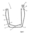
- a plant container or " osmopot" 1 comprising an outer layer 2 and an inner layer 3.
- the outer layer 2 defines the outer shape of the container 1 and, therefore, the aestnetic look of the container 1.
- the inner layer 3 defines an inner hollow 4.
- Between the outer layer 2 and the inner layer 3 is a space or reservoir 5 for the storage of fluid or water 6, with or without additional nutrients.
- a rim 7 of the container 1 has an opening or removably sealable opening 8 by which water 6 can be introduced into the reservoir 5.
- the rim 7 may be created by moulding the inner layer 3 and/or the outer layer 2 so that they join each other at or under the top surface of the rim 7, when the two layers 2 and 3 are joined together.
- a separate rim 7 may be used and fitted to the join the outer layer 2 and inner layer 3.
- the opening 8 can comprise a small hole in one area of the rim 7 and can obviously be of any suitable shape.
- the opening 8 is circular or oval and of a larger diameter than an average garden hose or watering can spout for ease of filling the reservoir 5.
- the opening 8 could be funnel-shaped for ease of filling, or the container 1 could be supplied with a funnel. Again alternatively, the opening 8 could run the full length or part of the length of the rim 7.
- the opening 8 has an airtight stopper 9 consisting of, for example, a bung of plastic, rubber, cork or wood, Alternatively, the stopper 9 is of moulded plastic fitted with a recessed " O" ring to form the seal with the opening 8.
- the stopper 9 may be attached to the container 1 by means of a plastic strip to prevent loss of the stopper 9 in use.
- the stopper 9 prevents loss of water 6 from the reservoir 5 by evaporation.
- the stopper 9 may also incorporate an indicator (not shown) to indicate the level of water 6 in the reservoir 5.
- the inner layer 3 has a cone-shaped base 10, at least one hole 11 is positioned at the central lowest point of the cone-shaped base 10. The hole 11 is small and allows water contact with soil or growing medium 12 in the inner hollow 4.
- the container or " osmopot" 1 delivers water 6 to a plant 13 growing in the inner hollow 4 in two ways.
- the first is by capillary action, water molecules diffuse from a region of high concentration in the reservoir 5 to an area of low concentration in the inner hollow 4.
- water 6 is also assisted to enter the inner hollow 4 from the reservoir 5 by fluctuations in the ambient temperature causing the air pressure in the reservoir above the water line to change. When the temperature rises the air pressure rises and the water 6 expands slightly and pushes a small amount of water 6 through the small hole 11. This wets the growing medium 12 and creates a capillary track in the inner hollow 4.
- all living plants 13 are hydrotropi.c, their roots sense the presence of water in the soil 12 and eventually contact will be made with a capillary track and by the process of osmosis the plant will draw a supply of water throughout its membraneous cell structures.
- the plant container or " osmopot" 1 may be made from a variety of materials, for example, ceramic materials, concrete materials, spun or cast metals, a variety of plastics and glass, or a mixture of any of the above materials.
- a plant 13 including a small tree or shrub, is planted conventionally in, for example, soil, growing medium, potting compost or water-carrying gel 12, in the inner hollow 4.
- the reservoir 5 is then filled with water or fluid 6 by means of the opening 8, liquid fertilizer can be added to the water 6.
- the stopper 9 is then placed in the opening 8 to seal the reservoir 5.
- the stopper 9 is designed to form an air lock or vacuum in the space or reservoir 5, failure to maintain the airtight seal of the stopper 9 may swamp the growing medium 12 in the inner hollow 4 with water 6 and, therefore, reduce the effectiveness of the watering system provided by the container or " osmopot" 1.
- the seal of the stopper 9 plus the small size of the hole 11 prevents water 6 flooding the growing medium 12 in the inner hollow 4.
- the water 6 stored in the reservoir 5 transfers naturally and slowly to the growing medium 12 and plant 13 in the inner hollow 4.
- the period of time between filling of the reservoir 5 will vary depending on the size of the container 1, the type of plant 13 and the external environment. Between four to six weeks is envisaged between refills.
- a plant 13 planted in the container 1 according to the present invention will be able to draw water as and when required. There is no over wetting or under supply of moisture, The plant 13 through its root system and with the temperature induced fluctuating air pressure within the reservoir 5 is able to draw an even supply of water against the vacuum pressure within the reservoir 5.
- the system of plant maintenance provided according to the container of the present invention allows the container 1 to be inverted without spillage of water 6 and any added nutrients. Further, as the water supply to the plant remains consistent, the plant is able to grow without the normal conditions for a potted plant of under and over supply of water cycles associated with conventional plant containers.
- the container 1 can be left for a number of weeks without resupply of water.
- an extra reservoir bottle (not shown) is filled and fitted or screwed into the opening 6.
- the reservoir 5 may be filled with, for example, foam or pebble-type porous materials, to add strength and rigidity to the container 1 while still acting as a reservoir 5 for water 6.
- the plant container according to the present invention can be of various shapes, such as, for example, square based and hexagonal based. Further the container can obviously be of different sizes and different proportions to sustain extended unattended plant growth.
- the base 10 can be of various shapes, however, the cone-shape is preferable, allowing maximum storage capacity in the reservoir 5 with a low central point for optimum conditions to allow transfer of water 6 to the inner hollow 4 to occur even at low water levels in the reservoir 5. But, it can be foreseen that alternative shapes, such as an inverted cone having many holes around the outer edge of the base 10, or a dome-shaped base 10 may also be used.
- the rim 7 may separately act as a removable sealable lid for the reservoir 5. Further, it can be foreseen that the opening 8 could be positioned in the side of the outer layer 2.
Landscapes
- Engineering & Computer Science (AREA)
- Water Supply & Treatment (AREA)
- Life Sciences & Earth Sciences (AREA)
- Environmental Sciences (AREA)
- Cultivation Receptacles Or Flower-Pots, Or Pots For Seedlings (AREA)
Abstract
Description
- The present invention relates to an improved plant container or " osmopot" for use in containing all types of plants, including shrubs and small trees, in both internal and external environments.
- Conventionally, plant containers are provided with a saucer which sits underneath the base of the container to hold water, the plant in the container can then be watered by filling the saucer. However, there is no regulation of the amount of water which enters the growing medium around the roots of the plant and, due to the large surface area of water in the saucer, much of the water will be lost by evaporation. In order to increase the amount of water given to a plant at one time, conventionally, a larger saucer is used. However, the larger saucer will have a larger surface area of water and, accordingly, a higher rate of evaporation. Further, rates of evaporation of water from the saucer caused by environmental conditions will be highest when the plants need for water is highest.
- Under and over watering of plants in conventional containers leads to stress of the plant. Further, many species of plants are particularly susceptible to over or under watering and this is a common cause for loss of potted plants. Accordingly, when using a conventional saucer it is often not desirable to fill the saucer to the top, since this will leave the roots of the plant standing in water which may cause the roots to rot, leading to loss of the plant. Therefore, it is necessary to water the plants little and often so they require constant care.
- When using liquid fertilizers or pesticides, in a conventional container, these will be added to the water in the saucer leading to an increased risk of pollution and the risk of pets drinking from the saucer.
- It is an object of the present invention to overcome the problems associated with plant containers in the past and to provide a plant container which retains water, without flooding the roots of the plant, and which, therefore, requires less frequent watering of the plant in the container.
- It is a further object of the present invention to provide a plant container which is cheap and easy to produce.
- It is a still further object of the present invention to provide a plant container which acts as a natural watering system that provides an even and consistent water supply to a plant potted in the container for indoor and outdoor environments.
- According to the present invention there is provided a plant container comprising an outer layer and an inner layer, having a reservoir defined between the outer layer and the inner layer, characterised in that the reservoir is filled with fluid via a removably sealable opening and the inner layer having at least one hole connecting to the reservoir.
- Preferably, the at least one hole in the inner layer is positioned at the lowest point of the inner layer. The base of the inner layer may be cone-shaped, the at least one hole being positioned at the central point of the cone-shape.
- Again preferably, the removably sealable opening is positioned in the rim of the container.
- The container may be of plastic or ceramic materials.
- In order to aid in understanding the invention some specific embodiments thereof will now be described by way of example and with reference to the accompanying drawings, in which:
- Figure 1 is a cross-sectional view showing a container according to the invention;
- Figure 2 is a cross-sectional view showing the container of Figure 1 in use.
-
- Referring to the Figures, there is shown a plant container or " osmopot" 1 comprising an
outer layer 2 and aninner layer 3. Theouter layer 2 defines the outer shape of the container 1 and, therefore, the aestnetic look of the container 1. Theinner layer 3 defines aninner hollow 4. Between theouter layer 2 and theinner layer 3 is a space orreservoir 5 for the storage of fluid orwater 6, with or without additional nutrients. Arim 7 of the container 1 has an opening or removablysealable opening 8 by whichwater 6 can be introduced into thereservoir 5. Therim 7 may be created by moulding theinner layer 3 and/or theouter layer 2 so that they join each other at or under the top surface of therim 7, when the twolayers separate rim 7 may be used and fitted to the join theouter layer 2 andinner layer 3. The opening 8 can comprise a small hole in one area of therim 7 and can obviously be of any suitable shape. Preferably theopening 8 is circular or oval and of a larger diameter than an average garden hose or watering can spout for ease of filling thereservoir 5. Alternatively, the opening 8 could be funnel-shaped for ease of filling, or the container 1 could be supplied with a funnel. Again alternatively, theopening 8 could run the full length or part of the length of therim 7. Theopening 8 has anairtight stopper 9 consisting of, for example, a bung of plastic, rubber, cork or wood, Alternatively, thestopper 9 is of moulded plastic fitted with a recessed " O" ring to form the seal with theopening 8. Thestopper 9 may be attached to the container 1 by means of a plastic strip to prevent loss of thestopper 9 in use. Thestopper 9 prevents loss ofwater 6 from thereservoir 5 by evaporation. Thestopper 9 may also incorporate an indicator (not shown) to indicate the level ofwater 6 in thereservoir 5. Theinner layer 3 has a cone-shaped base 10, at least one hole 11 is positioned at the central lowest point of the cone-shaped base 10. The hole 11 is small and allows water contact with soil or growingmedium 12 in theinner hollow 4. - The container or " osmopot" 1 delivers
water 6 to a plant 13 growing in the inner hollow 4 in two ways. The first is by capillary action, water molecules diffuse from a region of high concentration in thereservoir 5 to an area of low concentration in theinner hollow 4. Secondly,water 6 is also assisted to enter theinner hollow 4 from thereservoir 5 by fluctuations in the ambient temperature causing the air pressure in the reservoir above the water line to change. When the temperature rises the air pressure rises and thewater 6 expands slightly and pushes a small amount ofwater 6 through the small hole 11. This wets the growingmedium 12 and creates a capillary track in the inner hollow 4. As all living plants 13 are hydrotropi.c, their roots sense the presence of water in thesoil 12 and eventually contact will be made with a capillary track and by the process of osmosis the plant will draw a supply of water throughout its membraneous cell structures. - The plant container or " osmopot" 1 according to the present invention may be made from a variety of materials, for example, ceramic materials, concrete materials, spun or cast metals, a variety of plastics and glass, or a mixture of any of the above materials.
- In use, a plant 13, including a small tree or shrub, is planted conventionally in, for example, soil, growing medium, potting compost or water-carrying
gel 12, in theinner hollow 4. Thereservoir 5 is then filled with water orfluid 6 by means of the opening 8, liquid fertilizer can be added to thewater 6. Thestopper 9 is then placed in the opening 8 to seal thereservoir 5. Thestopper 9 is designed to form an air lock or vacuum in the space orreservoir 5, failure to maintain the airtight seal of thestopper 9 may swamp the growingmedium 12 in theinner hollow 4 withwater 6 and, therefore, reduce the effectiveness of the watering system provided by the container or " osmopot" 1. The seal of thestopper 9 plus the small size of the hole 11 preventswater 6 flooding the growingmedium 12 in the inner hollow 4. Provided the airtight seal of thestopper 9 is maintained, thewater 6 stored in thereservoir 5 transfers naturally and slowly to the growingmedium 12 and plant 13 in theinner hollow 4. The period of time between filling of thereservoir 5 will vary depending on the size of the container 1, the type of plant 13 and the external environment. Between four to six weeks is envisaged between refills. - A plant 13 planted in the container 1 according to the present invention will be able to draw water as and when required. There is no over wetting or under supply of moisture, The plant 13 through its root system and with the temperature induced fluctuating air pressure within the
reservoir 5 is able to draw an even supply of water against the vacuum pressure within thereservoir 5. - The system of plant maintenance provided according to the container of the present invention allows the container 1 to be inverted without spillage of
water 6 and any added nutrients. Further, as the water supply to the plant remains consistent, the plant is able to grow without the normal conditions for a potted plant of under and over supply of water cycles associated with conventional plant containers. The container 1 can be left for a number of weeks without resupply of water. To increase the period of time between refills an extra reservoir bottle (not shown) is filled and fitted or screwed into theopening 6. Thereservoir 5 may be filled with, for example, foam or pebble-type porous materials, to add strength and rigidity to the container 1 while still acting as areservoir 5 forwater 6. - It will be understood that various alterations and modifications may be made to the above embodiments without departing from the scope of the invention, for example, the plant container according to the present invention can be of various shapes, such as, for example, square based and hexagonal based. Further the container can obviously be of different sizes and different proportions to sustain extended unattended plant growth. Also, the
base 10 can be of various shapes, however, the cone-shape is preferable, allowing maximum storage capacity in thereservoir 5 with a low central point for optimum conditions to allow transfer ofwater 6 to theinner hollow 4 to occur even at low water levels in thereservoir 5. But, it can be foreseen that alternative shapes, such as an inverted cone having many holes around the outer edge of thebase 10, or a dome-shaped base 10 may also be used. Also, therim 7 may separately act as a removable sealable lid for thereservoir 5. Further, it can be foreseen that theopening 8 could be positioned in the side of theouter layer 2.
Claims (6)
- A plant container comprising an outer layer and an inner layer, having a reservoir defined between the outer layer and the inner layer, characterised in that the reservoir is filled with fluid via a removably sealable opening and the inner layer having at least one hole connecting to the reservoir.
- A plant container according to Claim 1, wherein the at least one hole in the inner layer is positioned at the lowest point of the inner layer.
- A plant container according to Claim 1 or 2, wherein the base of the inner layer is cone-shaped, the at least one hole being positioned at the central point of the cone-shape,
- A plant container according to any preceding claim, wherein the removably sealable opening is positioned in the rim of the container.
- A plant container according to any preceding claim, wherein the container is of plastic or ceramic materials.
- A plant container substantially as described herein with reference to the accompanying drawings.
Applications Claiming Priority (2)
| Application Number | Priority Date | Filing Date | Title |
|---|---|---|---|
| CN99231627U CN2369477Y (en) | 1999-05-13 | 1999-05-13 | Double layer water preserving flower pot |
| CN99231627 | 1999-05-13 |
Publications (2)
| Publication Number | Publication Date |
|---|---|
| EP1051902A2 true EP1051902A2 (en) | 2000-11-15 |
| EP1051902A3 EP1051902A3 (en) | 2001-03-14 |
Family
ID=5309429
Family Applications (1)
| Application Number | Title | Priority Date | Filing Date |
|---|---|---|---|
| EP00304021A Withdrawn EP1051902A3 (en) | 1999-05-13 | 2000-05-12 | Improved plant container |
Country Status (3)
| Country | Link |
|---|---|
| EP (1) | EP1051902A3 (en) |
| CN (1) | CN2369477Y (en) |
| GB (1) | GB2351218A (en) |
Cited By (1)
| Publication number | Priority date | Publication date | Assignee | Title |
|---|---|---|---|---|
| FR3114002A1 (en) * | 2020-09-15 | 2022-03-18 | Canopee Structures | Plant pot |
Families Citing this family (2)
| Publication number | Priority date | Publication date | Assignee | Title |
|---|---|---|---|---|
| CN110326456A (en) * | 2019-07-07 | 2019-10-15 | 周志疆 | A kind of biological bacteria energetic nourishing alms bowl and preparation method and application method |
| CN110883078B (en) * | 2019-11-11 | 2021-08-10 | 安徽金联地矿科技有限公司 | Soil remediation device and remediation method based on environmental protection |
Family Cites Families (6)
| Publication number | Priority date | Publication date | Assignee | Title |
|---|---|---|---|---|
| US4001967A (en) * | 1973-05-21 | 1977-01-11 | Swift June H | Self-watering planter and process of making |
| DK167796B1 (en) * | 1984-11-13 | 1993-12-20 | Alexander Wild | EQUIPMENT FOR SELF-EFFECTIVE IRRIGATION OF PLANTED SOIL |
| GB2233201A (en) * | 1989-06-23 | 1991-01-09 | Liou Shan Puu | Plant or flower pot |
| WO1995024826A1 (en) * | 1994-03-16 | 1995-09-21 | Philip Morgan Wilby | An automatic plant watering device |
| IT1280753B1 (en) * | 1995-04-07 | 1998-02-06 | Benito Cacciatore | SELF-IRRIGATING POT |
| WO1998053668A1 (en) * | 1997-05-30 | 1998-12-03 | Elizabeth Patricia Witehira | Fluid store and dispenser |
-
1999
- 1999-05-13 CN CN99231627U patent/CN2369477Y/en not_active Expired - Fee Related
-
2000
- 2000-05-11 GB GB0011325A patent/GB2351218A/en not_active Withdrawn
- 2000-05-12 EP EP00304021A patent/EP1051902A3/en not_active Withdrawn
Non-Patent Citations (1)
| Title |
|---|
| None |
Cited By (2)
| Publication number | Priority date | Publication date | Assignee | Title |
|---|---|---|---|---|
| FR3114002A1 (en) * | 2020-09-15 | 2022-03-18 | Canopee Structures | Plant pot |
| WO2022058663A1 (en) * | 2020-09-15 | 2022-03-24 | Canopee Structures | Plant pot |
Also Published As
| Publication number | Publication date |
|---|---|
| EP1051902A3 (en) | 2001-03-14 |
| CN2369477Y (en) | 2000-03-22 |
| GB2351218A (en) | 2000-12-27 |
| GB0011325D0 (en) | 2000-06-28 |
Similar Documents
| Publication | Publication Date | Title |
|---|---|---|
| US6370819B1 (en) | Plant watering system | |
| US6536159B1 (en) | Plant pot | |
| US5836106A (en) | Plant watering control device | |
| US20240349667A1 (en) | Self-watering device for container plants and method of using the same | |
| US9661810B2 (en) | Demand driven self-watering planter | |
| CN100435618C (en) | Plant cultivation method and plant cultivation implement | |
| IL146042A (en) | Plant cultivating container and plant cultivating method | |
| US4791755A (en) | Substrate for a cultivated plant | |
| US20150289461A1 (en) | Self-watering flowerpot | |
| CN2476937Y (en) | Environmental protective water saving and storing flowerpot | |
| US20190289802A1 (en) | Planting system | |
| EP1051902A2 (en) | Improved plant container | |
| RU93207U1 (en) | DEVICE FOR GROWING PLANTS | |
| CN202435915U (en) | Simple pot plant irrigation device | |
| JP4003103B2 (en) | Automatic watering plant cultivation container | |
| CN217011905U (en) | Planting pot | |
| JP4898161B2 (en) | flower pot | |
| JP2005040009A (en) | Bottom water supply type plant cultivation container | |
| JPH10113081A (en) | Plant cultivation device and plant shelf | |
| TWM599082U (en) | Substrate block for plant cultivation | |
| CN2311932Y (en) | Cultivation receptacle with watering means | |
| KR200288831Y1 (en) | The multi-purpose plant-container without drainage-hole which can be set indoor by recycling the empty beverage pet-bottle | |
| CN201067012Y (en) | Plant growth controlling container | |
| CN216722282U (en) | Novel orchid planting cup | |
| CN2508548Y (en) | Water manure controllable cultivating flowerpot |
Legal Events
| Date | Code | Title | Description |
|---|---|---|---|
| PUAI | Public reference made under article 153(3) epc to a published international application that has entered the european phase |
Free format text: ORIGINAL CODE: 0009012 |
|
| AK | Designated contracting states |
Kind code of ref document: A2 Designated state(s): AT BE CH CY DE DK ES FI FR GB GR IE IT LI LU MC NL PT SE |
|
| AX | Request for extension of the european patent |
Free format text: AL;LT;LV;MK;RO;SI |
|
| PUAL | Search report despatched |
Free format text: ORIGINAL CODE: 0009013 |
|
| AK | Designated contracting states |
Kind code of ref document: A3 Designated state(s): AT BE CH CY DE DK ES FI FR GB GR IE IT LI LU MC NL PT SE |
|
| AX | Request for extension of the european patent |
Free format text: AL;LT;LV;MK;RO;SI |
|
| AKX | Designation fees paid | ||
| STAA | Information on the status of an ep patent application or granted ep patent |
Free format text: STATUS: THE APPLICATION IS DEEMED TO BE WITHDRAWN |
|
| 18D | Application deemed to be withdrawn |
Effective date: 20010915 |
|
| REG | Reference to a national code |
Ref country code: DE Ref legal event code: 8566 |