EP1050774A2 - Temperaturabhängiger optischer Dämpfungsregler - Google Patents
Temperaturabhängiger optischer Dämpfungsregler Download PDFInfo
- Publication number
- EP1050774A2 EP1050774A2 EP00303261A EP00303261A EP1050774A2 EP 1050774 A2 EP1050774 A2 EP 1050774A2 EP 00303261 A EP00303261 A EP 00303261A EP 00303261 A EP00303261 A EP 00303261A EP 1050774 A2 EP1050774 A2 EP 1050774A2
- Authority
- EP
- European Patent Office
- Prior art keywords
- article according
- polarizer
- temperature
- faraday rotation
- polarization direction
- Prior art date
- Legal status (The legal status is an assumption and is not a legal conclusion. Google has not performed a legal analysis and makes no representation as to the accuracy of the status listed.)
- Granted
Links
- 230000003287 optical effect Effects 0.000 title claims abstract description 27
- 230000001419 dependent effect Effects 0.000 title description 3
- 239000000203 mixture Substances 0.000 claims abstract description 21
- XEEYBQQBJWHFJM-UHFFFAOYSA-N Iron Chemical compound [Fe] XEEYBQQBJWHFJM-UHFFFAOYSA-N 0.000 claims description 29
- 230000010287 polarization Effects 0.000 claims description 14
- 229910052742 iron Inorganic materials 0.000 claims description 10
- 229910052761 rare earth metal Inorganic materials 0.000 claims description 9
- 150000002910 rare earth metals Chemical class 0.000 claims description 9
- 238000004891 communication Methods 0.000 claims description 8
- 239000013307 optical fiber Substances 0.000 claims description 7
- 239000000126 substance Substances 0.000 claims description 5
- 230000005540 biological transmission Effects 0.000 claims description 4
- 239000000758 substrate Substances 0.000 claims description 4
- 238000001816 cooling Methods 0.000 claims description 3
- 238000010438 heat treatment Methods 0.000 claims description 3
- CCRAOWWOICDIGI-UHFFFAOYSA-N [Zr].[Ca].[Mg] Chemical group [Zr].[Ca].[Mg] CCRAOWWOICDIGI-UHFFFAOYSA-N 0.000 claims description 2
- ZPDRQAVGXHVGTB-UHFFFAOYSA-N gallium;gadolinium(3+);oxygen(2-) Chemical class [O-2].[O-2].[O-2].[Ga+3].[Gd+3] ZPDRQAVGXHVGTB-UHFFFAOYSA-N 0.000 claims description 2
- 239000002223 garnet Substances 0.000 claims 5
- QVGXLLKOCUKJST-UHFFFAOYSA-N atomic oxygen Chemical compound [O] QVGXLLKOCUKJST-UHFFFAOYSA-N 0.000 claims 3
- 229910052733 gallium Inorganic materials 0.000 claims 3
- 229910052760 oxygen Inorganic materials 0.000 claims 3
- 239000001301 oxygen Substances 0.000 claims 3
- 230000005415 magnetization Effects 0.000 description 25
- 230000005291 magnetic effect Effects 0.000 description 14
- 239000000463 material Substances 0.000 description 11
- 239000000835 fiber Substances 0.000 description 7
- 238000000034 method Methods 0.000 description 4
- 230000006911 nucleation Effects 0.000 description 3
- 238000010899 nucleation Methods 0.000 description 3
- 229910052689 Holmium Inorganic materials 0.000 description 2
- 229910052771 Terbium Inorganic materials 0.000 description 2
- 230000008878 coupling Effects 0.000 description 2
- 238000010168 coupling process Methods 0.000 description 2
- 238000005859 coupling reaction Methods 0.000 description 2
- 230000000694 effects Effects 0.000 description 2
- 238000003780 insertion Methods 0.000 description 2
- 230000037431 insertion Effects 0.000 description 2
- 230000005381 magnetic domain Effects 0.000 description 2
- 239000000155 melt Substances 0.000 description 2
- 229910052693 Europium Inorganic materials 0.000 description 1
- 229910052769 Ytterbium Inorganic materials 0.000 description 1
- 238000013459 approach Methods 0.000 description 1
- 230000002301 combined effect Effects 0.000 description 1
- 230000003750 conditioning effect Effects 0.000 description 1
- 239000013078 crystal Substances 0.000 description 1
- 230000007423 decrease Effects 0.000 description 1
- 230000005292 diamagnetic effect Effects 0.000 description 1
- 238000002474 experimental method Methods 0.000 description 1
- 230000005294 ferromagnetic effect Effects 0.000 description 1
- 150000002500 ions Chemical class 0.000 description 1
- 238000012886 linear function Methods 0.000 description 1
- 238000004943 liquid phase epitaxy Methods 0.000 description 1
- 229910021645 metal ion Inorganic materials 0.000 description 1
- 230000001902 propagating effect Effects 0.000 description 1
- 238000009877 rendering Methods 0.000 description 1
- 229920006395 saturated elastomer Polymers 0.000 description 1
- 238000009738 saturating Methods 0.000 description 1
- 230000035945 sensitivity Effects 0.000 description 1
- 230000000087 stabilizing effect Effects 0.000 description 1
- 238000003756 stirring Methods 0.000 description 1
- 238000006467 substitution reaction Methods 0.000 description 1
Images


Classifications
-
- G—PHYSICS
- G02—OPTICS
- G02F—OPTICAL DEVICES OR ARRANGEMENTS FOR THE CONTROL OF LIGHT BY MODIFICATION OF THE OPTICAL PROPERTIES OF THE MEDIA OF THE ELEMENTS INVOLVED THEREIN; NON-LINEAR OPTICS; FREQUENCY-CHANGING OF LIGHT; OPTICAL LOGIC ELEMENTS; OPTICAL ANALOGUE/DIGITAL CONVERTERS
- G02F1/00—Devices or arrangements for the control of the intensity, colour, phase, polarisation or direction of light arriving from an independent light source, e.g. switching, gating or modulating; Non-linear optics
- G02F1/01—Devices or arrangements for the control of the intensity, colour, phase, polarisation or direction of light arriving from an independent light source, e.g. switching, gating or modulating; Non-linear optics for the control of the intensity, phase, polarisation or colour
- G02F1/09—Devices or arrangements for the control of the intensity, colour, phase, polarisation or direction of light arriving from an independent light source, e.g. switching, gating or modulating; Non-linear optics for the control of the intensity, phase, polarisation or colour based on magneto-optical elements, e.g. exhibiting Faraday effect
- G02F1/093—Devices or arrangements for the control of the intensity, colour, phase, polarisation or direction of light arriving from an independent light source, e.g. switching, gating or modulating; Non-linear optics for the control of the intensity, phase, polarisation or colour based on magneto-optical elements, e.g. exhibiting Faraday effect used as non-reciprocal devices, e.g. optical isolators, circulators
-
- G—PHYSICS
- G02—OPTICS
- G02F—OPTICAL DEVICES OR ARRANGEMENTS FOR THE CONTROL OF LIGHT BY MODIFICATION OF THE OPTICAL PROPERTIES OF THE MEDIA OF THE ELEMENTS INVOLVED THEREIN; NON-LINEAR OPTICS; FREQUENCY-CHANGING OF LIGHT; OPTICAL LOGIC ELEMENTS; OPTICAL ANALOGUE/DIGITAL CONVERTERS
- G02F1/00—Devices or arrangements for the control of the intensity, colour, phase, polarisation or direction of light arriving from an independent light source, e.g. switching, gating or modulating; Non-linear optics
- G02F1/01—Devices or arrangements for the control of the intensity, colour, phase, polarisation or direction of light arriving from an independent light source, e.g. switching, gating or modulating; Non-linear optics for the control of the intensity, phase, polarisation or colour
- G02F1/09—Devices or arrangements for the control of the intensity, colour, phase, polarisation or direction of light arriving from an independent light source, e.g. switching, gating or modulating; Non-linear optics for the control of the intensity, phase, polarisation or colour based on magneto-optical elements, e.g. exhibiting Faraday effect
Definitions
- This invention pertains to articles and systems (collectively “articles”) that comprise a variable optical attenuator.
- Variable optical attenuators potentially have a variety of important uses in optical communication systems. For instance, in wavelength division multiplexed (WDM) systems they could be used to tune the wavelength dependent gain of fiber amplifiers such that all wavelengths of interest have substantially the same gain. Variable optical attenuators exemplarily could also be used to compensate for variable input strengths to achieve a constant output, or to compensate for variable path length attenuation to produce equal strength signals. Desirably, variable attenuators for optical communication systems have attenuation up to about 20-25 dB, and insertion loss of about 1.5 dB or less.
- WDM wavelength division multiplexed
- variable optical attenuators including mechanical ones. See, for instance, S. Masuda, Applied Optics , Vol. 19, p. 2435 (1980), and W.L. Emkey, Optics Letters , Vol. 8, p. 94(1983).
- Mechanical devices are unlikely to achieve the speed required for high bit rate systems.
- R. Wolfe et al., Applied Physics Letters , Vol. 58, p. 1733 (1991) suggested a device based on a single domain wall in a magnetooptic waveguide. Such a device however would be costly to fabricate, and have high insertion loss for coupling to fiber.
- Fukushima et al. (Optical Society of America TOPS on Optical Amplifiers and Their Applications, 1996 ,Vol. 5, 1996 OAA Program Committee (eds), pp. 249-252), have disclosed a thick magnetic film with in-plane magnetization, where the direction of the magnetization in the plane depends on a relatively small magnetic bias field.
- the Faraday rotation in the direction of light propagation depends on the cosine of the angle between the magnetization and the direction of propagation. This approach has drawbacks with the in-plane coupling of light and the non- uniformity of magnetization with bias field because of the cubic magnetic anisotropy of the film.
- variable optical attenuators In view of the many potential uses of variable optical attenuators, it would be desirable to have available a compact, low power device having a significant tuning range. This application discloses such a device.
- RIGs rare earth iron garnets
- M s (T)
- M c , M a and M d are the sublattice magnetizations of the dodecahedral, octahedral and tetrahedral sublattices, respectively, and T is the absolute temperature.
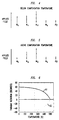
- FIG. 1 schematically shows the sublattice magnetization as a function of temperature of the three sublattices of an exemplary RIG
- FIG. 2 shows the resulting net magnetization as a function of temperature.
- the rare earth contribution, for heavy rare earth's is large at low temperatures but is substantially negligible at high temperatures. Consequently, such RIGs can exhibit magnetic compensation (i.e., zero saturation magnetization) at some temperature below the Curie temperature.
- FIG. 2 where the compensation temperature is about 250K and the Curie temperature is about 500K.
- the temperature dependence of the rare earth moment is highest for Gd and decreases steadily through the heavy rare earths. Data for Tb, Ho and Yb are shown in FIG.3.
- the Faraday rotation of a RIG of interest herein typically does not go to zero at the compensation temperature.
- the sign of the saturation magnetization changes with respect to the sublattice magnetizations, and therefore with respect to the Faraday rotation.
- the compensation temperature of a particular RIG material generally is determined by the combined effects of the dodecahedral ions (particular the concentration of heavy rare earths) and the diamagnetic substitution on the iron sites.
- the sublattice magnetization will change sign, as shown schematically in FIGs. 4 and 5. This typically occurs by a process of nucleation and growth of a region (or regions) of reverse sublattice magnetization into the existing domain. During this process, these magnetic domains with differently ordered sublattices are separated by a special kind of magnetic domain wall, generally referred to as a "compensation wall".
- the sublattices on one side of the compensation wall are oriented antiparallel to the corresponding sublattices on the other side of the compensation wall.
- the compensation wall has somewhat less energy than a randomly oriented domain wall, but its nucleation still requires some energy. Consequently, there is hysteresis in switching a material of uniform composition, similar to the nucleation-induced coercivity in LatchingTM Faraday rotators.
- the instant invention is embodied in a variable attenuator for light of wavelength ⁇ , exemplarily 1.55 ⁇ m or 1.3 ⁇ m, and is also embodied in an article (e.g., an optical fiber communication system) that comprises such a variable attenuator.
- the prior art contains an optical device that is adapted to support propagation of light of wavelength ⁇ in a downstream direction from an input port to an output port through the device.
- the article further comprises a first and a second polarizer, each polarizer having a polarization direction, with the polarization direction of the second polarizer being substantially 45°C from the polarization direction of the first polarizer, with the second polarizer being spaced in the downstream direction from the first polarizer.
- the article further comprises Faraday rotation means disposed between the first and second polarizer and selected to change, when fully magnetized in the forward propagation direction, the polarization direction of light of wavelength ⁇ from a direction parallel to the polarization direction of the first polarizer to a direction substantially parallel to the polarization direction of the second polarizer.
- the article still further comprises a magnet selected to substantially magnetically saturate the Faraday rotation means in a predetermined direction, and also comprises heating and/or cooling means selected for varying a temperature of the Faraday rotation means.
- the optical device is a variable optical attenuator for said light of wavelength ⁇ .
- the Faraday rotation means comprise a magnetooptic body having a chemical composition that varies in the downstream direction, the chemical composition selected such that the magnetooptic body comprises a compensation wall that is movable in response to a change in the temperature of the magnetooptic body, whereby the attenuation of the light of wavelength ⁇ is changed.
- the composition of the magnetooptic body (typically a RIG) varies substantially continuously along the downstream (axial) direction.
- the composition is selected such that the variable attenuator has a gradient in compensation temperature of ⁇ T(e.g., ⁇ 5°C) about a center temperature.
- the center temperature exemplarily is an expected operating temperature T o , e.g., room temperature ( ⁇ 22°C).
- T o room temperature
- the attenuator has a predetermined attenuation Z o (e.g., 0.1 dB), and changing the temperature of the magnetooptic body, e.g., by means of a thermoelectric cooler and heater combination results in a predetermined change in the attenuation.
- a compensation wall is always present. Exemplarily this is assured by growth of a thin layer of either high or low (depending on the direction of the composition gradient) compensation temperature material on one of the major surfaces of the magnetooptic element.
- a permanent magnet provides the magnetic field that is required to move the compensation wall in response to a temperature change.
- the cost of a permanent magnet increases with increasing field strength. Thus, a compromise will typically be required. Some simple experiments will generally suffice to determine an acceptable magnet strength.
- An electromagnet of course could also be used to provide the desired magnetic field.
- variable attenuator can be advantageously used for automatic gain control in a WDM optical fiber communication system with a fiber amplifier, or for stabilizing the output level of a fiber amplifier.
- FIG. 7 schematically depicts an exemplary variable attenuator 70 according to the invention.
- Numeral 71 refers to a magnetooptic body (typically a 45° Faraday rotator with appropriate compositional variation)
- numerals 72 and 73 refer, respectively, to a first polarizer that defines the 0° polarization direction and a second polarizer that has polarization direction 45° from the 0° direction
- numeral 74 refers to a thermoelectric (TE) cooling plus heating device.
- the magnetooptic body is heat-conductively attached to the TE device.
- Numerals 75 refer to a magnet, exemplarily a tubular permanent magnet of strength sufficient to magnetically saturate the Faraday rotator.
- Light 76 is incident on the first polarizer and propagates in axial direction (downstream) through the variable attenuator.
- variable attenuator comprises conventional features similar to features found in optical isolators, e.g., one or more optical lenses for conditioning of the light beam, and means for attaching fiber "pig tails" to the device. These features are not shown in FIG. 7.
- FIG. 6 schematically shows Faraday rotation as a function of temperature for a compensation point material, with curve 61 pertaining to the case of zero applied magnetic field in a coercive material, and 62 to an applied field.
- FIG. 6 illustrates the change of sign of the Faraday rotation at the compensation temperature. It is this change of sign that underlies the utility of magnetooptic material with an appropriate compensation temperature for variable attenuators.
- the magnetooptic body has a composition gradient about a central composition.
- the central composition is approximately Bi 1.2 Eu 0.9 Ho 0.9 Fe 4.0 Ga 1.0 O 12 .
- This composition is expected to have a compensation temperature of approximately 22°C.
- the central temperature can be set to other desired operating temperatures.
- a gradient in the compensation temperature can be introduced inter alia by a gradient in the Bi/(Eu+Ho) ratio in the body. Because Bi is not magnetic while Eu and Ho are magnetic, changing the Bi/(Eu+Ho) ratio changes the c-lattice contribution to the magnetization and thereby affects the compensation temperature.
- compositions are exemplary only, and other materials with different center temperatures and/or gradients could be devised, depending inter alia on the desired operating range and sensitivity of the variable attenuator.
- RIGs for use in a variable optical attenuator according to the invention can be grown by a technique substantially as described in U.S. Patent 5,608,570.
- to achieve the desired composition gradient typically requires a variation of the prior art procedure.
- the undercooling of the melt can be varied smoothly. Since Bi concentration is approximately a linear function of undercooling for a given melt (see, for instance, C.-P Klages et al., J. Crystal Growth , Vol. 64, p. 275 (1983)), the desired composition gradient can be established.
- the Bi concentration can also be varied by varying the rotation rate.
- Theory predicts a Bi concentration that varies as the square root of the rotation rate. However, we have found that for rotation rates in the approximate range 40-160 rpm, little change occurs in the distribution coefficient of Bi. Rotation rates below about 40 are found to be effective in reducing the Bi concentration, with zero rotation generally not being indicated, due to insufficient stirring of the melt. In previous work it was shown that a change of 0.02-0.05 Bi atoms/formula unit is readily achievable by variation of the film rotation rate.
- RIGs according to the invention are typically grown as single crystal film on a substrate, e.g., calcium magnesium zirconium substituted gadolinium gallium garnet (CMZ:GGG) of lattice parameter 12.498A.
- a substrate e.g., calcium magnesium zirconium substituted gadolinium gallium garnet (CMZ:GGG) of lattice parameter 12.498A.
- CZ:GGG calcium magnesium zirconium substituted gadolinium gallium garnet
- FIG. 8 schematically depicts an exemplary optical fiber communication system 80.
- the system comprises a conventional transmitter 81, a conventional receiver 85, and an optical fiber transmission path (including transmission fiber 83) that signal-transmissively connects the transmitter and receiver, and comprises conventional optical fiber amplifier 84 and variable attenuator according to the invention 70.
- Pump source 86 provides pump light to the amplifier. It will be understood that the presence of a fiber laser in the transmission path is optional, and that other optical components (e.g., a router) could be present.
- the communication system typically is a multichannel (WDM) system.
- WDM multichannel
Landscapes
- Physics & Mathematics (AREA)
- Nonlinear Science (AREA)
- Engineering & Computer Science (AREA)
- Power Engineering (AREA)
- General Physics & Mathematics (AREA)
- Optics & Photonics (AREA)
- Optical Modulation, Optical Deflection, Nonlinear Optics, Optical Demodulation, Optical Logic Elements (AREA)
Applications Claiming Priority (2)
| Application Number | Priority Date | Filing Date | Title |
|---|---|---|---|
| US304287 | 1999-05-03 | ||
| US09/304,287 US5978135A (en) | 1999-05-03 | 1999-05-03 | Article comprising a variable optical attenuator |
Publications (3)
| Publication Number | Publication Date |
|---|---|
| EP1050774A2 true EP1050774A2 (de) | 2000-11-08 |
| EP1050774A3 EP1050774A3 (de) | 2002-07-17 |
| EP1050774B1 EP1050774B1 (de) | 2006-10-25 |
Family
ID=23175855
Family Applications (1)
| Application Number | Title | Priority Date | Filing Date |
|---|---|---|---|
| EP00303261A Expired - Lifetime EP1050774B1 (de) | 1999-05-03 | 2000-04-18 | Variabler optischer Abschwächer mit einem temperaturabhängigen Faraday Rotator |
Country Status (4)
| Country | Link |
|---|---|
| US (1) | US5978135A (de) |
| EP (1) | EP1050774B1 (de) |
| JP (1) | JP3699330B2 (de) |
| DE (1) | DE60031475T2 (de) |
Families Citing this family (10)
| Publication number | Priority date | Publication date | Assignee | Title |
|---|---|---|---|---|
| JP3720616B2 (ja) * | 1999-02-24 | 2005-11-30 | Fdk株式会社 | ファラデー回転角可変装置 |
| US6553175B2 (en) | 2000-01-21 | 2003-04-22 | Sycamore Networks, Inc. | Variable optical attenuator |
| US7336418B1 (en) | 2000-03-01 | 2008-02-26 | Fdk Corporation | Optical attenuator |
| WO2002029477A1 (fr) | 2000-10-04 | 2002-04-11 | Mitsubishi Denki Kabushiki Kaisha | Attenuateur optique variable |
| US6646777B2 (en) * | 2002-02-27 | 2003-11-11 | Jds Uniphase Corporation | Optical isolator with improved mounting characteristics |
| US7068413B1 (en) * | 2005-05-18 | 2006-06-27 | The United States Of America As Represented By The Secretary Of The Air Force | Near-normal incidence quasi-optical reflective Faraday rotator for high power millimeter wave radars |
| US7791886B2 (en) * | 2006-08-25 | 2010-09-07 | Shinkosha Co., Ltd. | Heat-dissipating structure for an optical isolator |
| CN105044934A (zh) * | 2015-08-06 | 2015-11-11 | 深圳市创鑫激光股份有限公司 | 一种光隔离器、激光输出头及激光设备 |
| CN105938973A (zh) * | 2016-06-21 | 2016-09-14 | 沈阳理工大学 | 一种新型高精度激光能量/功率衰减器 |
| JP7218355B2 (ja) * | 2017-08-28 | 2023-02-06 | ローレンス・リバモア・ナショナル・セキュリティ・エルエルシー | ガス冷却ファラデー回転子および方法 |
Family Cites Families (6)
| Publication number | Priority date | Publication date | Assignee | Title |
|---|---|---|---|---|
| DE2252715C3 (de) * | 1972-10-27 | 1980-04-30 | Philips Patentverwaltung Gmbh, 2000 Hamburg | Optisch transparente Einkristallscheibe aus substituiertem Eisen-Granat und Verfahren zu ihrer Herstellung |
| NL7509733A (nl) * | 1975-08-15 | 1977-02-17 | Philips Nv | Inrichting voor magnetische domeinen volgens een dichte pakking. |
| JPS63273828A (ja) * | 1987-05-01 | 1988-11-10 | Nec Corp | 光アイソレ−タ |
| US4981341A (en) * | 1989-07-14 | 1991-01-01 | At&T Bell Laboratories | Apparatus comprising a magneto-optic isolator utilizing a garnet layer |
| US5703710A (en) * | 1994-09-09 | 1997-12-30 | Deacon Research | Method for manipulating optical energy using poled structure |
| US5608570A (en) * | 1995-07-05 | 1997-03-04 | Lucent Technologies Inc. | Article comprising a magneto-optic material having low magnetic moment |
-
1999
- 1999-05-03 US US09/304,287 patent/US5978135A/en not_active Expired - Lifetime
-
2000
- 2000-04-18 DE DE60031475T patent/DE60031475T2/de not_active Expired - Lifetime
- 2000-04-18 EP EP00303261A patent/EP1050774B1/de not_active Expired - Lifetime
- 2000-05-01 JP JP2000132827A patent/JP3699330B2/ja not_active Expired - Fee Related
Also Published As
| Publication number | Publication date |
|---|---|
| US5978135A (en) | 1999-11-02 |
| EP1050774B1 (de) | 2006-10-25 |
| DE60031475D1 (de) | 2006-12-07 |
| JP3699330B2 (ja) | 2005-09-28 |
| DE60031475T2 (de) | 2007-06-21 |
| JP2000347151A (ja) | 2000-12-15 |
| EP1050774A3 (de) | 2002-07-17 |
Similar Documents
| Publication | Publication Date | Title |
|---|---|---|
| Levy et al. | Integrated optical isolators with sputter-deposited thin-film magnets | |
| US5408565A (en) | Thin-film magneto-optic polarization rotator | |
| JP2591542B2 (ja) | 光学装置、少なくとも2つの光学システムを製造する方法、および光学システムを使用する方法 | |
| US4981341A (en) | Apparatus comprising a magneto-optic isolator utilizing a garnet layer | |
| US5978135A (en) | Article comprising a variable optical attenuator | |
| US7006273B2 (en) | Faraday rotation device and optical device using same | |
| US5521741A (en) | Polarization plane switch and optical switching device using the same | |
| US5801875A (en) | Article comprising a magneto-optic material having low magnetic moment | |
| EP0940704B1 (de) | Faraday-Rotator | |
| US5608570A (en) | Article comprising a magneto-optic material having low magnetic moment | |
| US5898516A (en) | Faraday rotator having a rectangular shaped hysteresis | |
| US6775052B2 (en) | Hard magnetic garnet material, faraday rotator, optical device, optical communication system, method of manufacturing faraday rotator and method of manufacturing bismuth-substituted rare earth iron garnet single crystal | |
| US7555177B1 (en) | All fiber magneto-optic on-off switch for networking applications | |
| US6392784B1 (en) | Faraday rotator | |
| RU2138069C1 (ru) | Магнитооптическая тонкопленочная структура | |
| JP4220267B2 (ja) | ファラデー回転子及びそれを用いた光部品 | |
| Fratello et al. | Growth and characterization of magnetooptic garnet films with planar uniaxial anisotropy | |
| US6031654A (en) | Low magnet-saturation bismuth-substituted rare-earth iron garnet single crystal film | |
| Fratello et al. | Compositional design of Faraday rotator materials | |
| US5204868A (en) | Optical isolator and method for assembling same | |
| JP3953812B2 (ja) | 硬磁性ガーネット材料、ファラデー回転子、光アイソレータおよび光通信システム | |
| JP2003195241A (ja) | ファラデー回転子の製造方法、ファラデー回転子、ビスマス置換型希土類鉄ガーネット単結晶膜の製造方法、光アイソレータ | |
| Warbrick | Design of a compact optical isolator | |
| Dötsch et al. | Application of magnetic garnet films for magnetooptical imaging of magnetic field distributions | |
| JP2002174802A (ja) | 光アッテネータ |
Legal Events
| Date | Code | Title | Description |
|---|---|---|---|
| PUAI | Public reference made under article 153(3) epc to a published international application that has entered the european phase |
Free format text: ORIGINAL CODE: 0009012 |
|
| AK | Designated contracting states |
Kind code of ref document: A2 Designated state(s): AT BE CH CY DE DK ES FI FR GB GR IE IT LI LU MC NL PT SE |
|
| AX | Request for extension of the european patent |
Free format text: AL;LT;LV;MK;RO;SI |
|
| RAP1 | Party data changed (applicant data changed or rights of an application transferred) |
Owner name: AGERE SYSTEMS OPTOELECTRONICS GUARDIAN CORPORATION |
|
| PUAL | Search report despatched |
Free format text: ORIGINAL CODE: 0009013 |
|
| AK | Designated contracting states |
Kind code of ref document: A3 Designated state(s): AT BE CH CY DE DK ES FI FR GB GR IE IT LI LU MC NL PT SE |
|
| AX | Request for extension of the european patent |
Free format text: AL;LT;LV;MK;RO;SI |
|
| 17P | Request for examination filed |
Effective date: 20030114 |
|
| AKX | Designation fees paid |
Designated state(s): DE FR GB |
|
| RIC1 | Information provided on ipc code assigned before grant |
Ipc: G02F 1/09 20060101AFI20060228BHEP |
|
| RTI1 | Title (correction) |
Free format text: VARIABLE OPTICAL ATTENUATOR USING A TEMPERATURE DEPENDENT FARADAY ROTATOR |
|
| GRAP | Despatch of communication of intention to grant a patent |
Free format text: ORIGINAL CODE: EPIDOSNIGR1 |
|
| GRAS | Grant fee paid |
Free format text: ORIGINAL CODE: EPIDOSNIGR3 |
|
| GRAA | (expected) grant |
Free format text: ORIGINAL CODE: 0009210 |
|
| AK | Designated contracting states |
Kind code of ref document: B1 Designated state(s): DE FR GB |
|
| REG | Reference to a national code |
Ref country code: GB Ref legal event code: FG4D |
|
| REF | Corresponds to: |
Ref document number: 60031475 Country of ref document: DE Date of ref document: 20061207 Kind code of ref document: P |
|
| ET | Fr: translation filed | ||
| PLBE | No opposition filed within time limit |
Free format text: ORIGINAL CODE: 0009261 |
|
| STAA | Information on the status of an ep patent application or granted ep patent |
Free format text: STATUS: NO OPPOSITION FILED WITHIN TIME LIMIT |
|
| 26N | No opposition filed |
Effective date: 20070726 |
|
| PGFP | Annual fee paid to national office [announced via postgrant information from national office to epo] |
Ref country code: GB Payment date: 20140416 Year of fee payment: 15 |
|
| PGFP | Annual fee paid to national office [announced via postgrant information from national office to epo] |
Ref country code: DE Payment date: 20140430 Year of fee payment: 15 Ref country code: FR Payment date: 20140409 Year of fee payment: 15 |
|
| REG | Reference to a national code |
Ref country code: DE Ref legal event code: R119 Ref document number: 60031475 Country of ref document: DE |
|
| GBPC | Gb: european patent ceased through non-payment of renewal fee |
Effective date: 20150418 |
|
| PG25 | Lapsed in a contracting state [announced via postgrant information from national office to epo] |
Ref country code: GB Free format text: LAPSE BECAUSE OF NON-PAYMENT OF DUE FEES Effective date: 20150418 Ref country code: DE Free format text: LAPSE BECAUSE OF NON-PAYMENT OF DUE FEES Effective date: 20151103 |
|
| REG | Reference to a national code |
Ref country code: FR Ref legal event code: ST Effective date: 20151231 |
|
| PG25 | Lapsed in a contracting state [announced via postgrant information from national office to epo] |
Ref country code: FR Free format text: LAPSE BECAUSE OF NON-PAYMENT OF DUE FEES Effective date: 20150430 |