EP1050686A2 - Kolben- und Zylinderaggregat und Durchflussbegrenzer dafür - Google Patents
Kolben- und Zylinderaggregat und Durchflussbegrenzer dafür Download PDFInfo
- Publication number
- EP1050686A2 EP1050686A2 EP00303658A EP00303658A EP1050686A2 EP 1050686 A2 EP1050686 A2 EP 1050686A2 EP 00303658 A EP00303658 A EP 00303658A EP 00303658 A EP00303658 A EP 00303658A EP 1050686 A2 EP1050686 A2 EP 1050686A2
- Authority
- EP
- European Patent Office
- Prior art keywords
- piston
- ring
- cylinder
- assembly
- flow path
- Prior art date
- Legal status (The legal status is an assumption and is not a legal conclusion. Google has not performed a legal analysis and makes no representation as to the accuracy of the status listed.)
- Withdrawn
Links
Images


Classifications
-
- F—MECHANICAL ENGINEERING; LIGHTING; HEATING; WEAPONS; BLASTING
- F15—FLUID-PRESSURE ACTUATORS; HYDRAULICS OR PNEUMATICS IN GENERAL
- F15B—SYSTEMS ACTING BY MEANS OF FLUIDS IN GENERAL; FLUID-PRESSURE ACTUATORS, e.g. SERVOMOTORS; DETAILS OF FLUID-PRESSURE SYSTEMS, NOT OTHERWISE PROVIDED FOR
- F15B15/00—Fluid-actuated devices for displacing a member from one position to another; Gearing associated therewith
- F15B15/20—Other details, e.g. assembly with regulating devices
- F15B15/22—Other details, e.g. assembly with regulating devices for accelerating or decelerating the stroke
- F15B15/222—Other details, e.g. assembly with regulating devices for accelerating or decelerating the stroke having a piston with a piston extension or piston recess which throttles the main fluid outlet as the piston approaches its end position
-
- F—MECHANICAL ENGINEERING; LIGHTING; HEATING; WEAPONS; BLASTING
- F15—FLUID-PRESSURE ACTUATORS; HYDRAULICS OR PNEUMATICS IN GENERAL
- F15B—SYSTEMS ACTING BY MEANS OF FLUIDS IN GENERAL; FLUID-PRESSURE ACTUATORS, e.g. SERVOMOTORS; DETAILS OF FLUID-PRESSURE SYSTEMS, NOT OTHERWISE PROVIDED FOR
- F15B15/00—Fluid-actuated devices for displacing a member from one position to another; Gearing associated therewith
- F15B15/20—Other details, e.g. assembly with regulating devices
- F15B15/22—Other details, e.g. assembly with regulating devices for accelerating or decelerating the stroke
- F15B15/224—Other details, e.g. assembly with regulating devices for accelerating or decelerating the stroke having a piston which closes off fluid outlets in the cylinder bore by its own movement
Definitions
- This invention relates to a piston and cylinder assembly, wherein the piston partially defines a fluid chamber in the cylinder from which fluid is expelled through an outlet port of the cylinder by movement of the piston along the cylinder.
- the invention also includes a flow restrictor device for use in such a piston and cylinder arrangement.
- a flow restrictor device in the form of a snubbing ring carried by the piston and having an axially extending groove in its outer peripheral surface communicating with the port.
- the ring partially seals the port and the ring groove provides restricted communication between the chamber and port, permitting the piston to be decelerated in a controlled manner towards the end of its operative stroke.
- the invention provides a piston and cylinder assembly, wherein the piston partially defines a fluid chamber in the cylinder from which fluid is expelled through an outlet port of the cylinder by movement of the piston along the cylinder, the assembly including flow restrictor means providing a first restricted flow path between the chamber and port, said means also providing an auxiliary restricted flow path of which a first portion communicates with the chamber and of which a second portion extends between the first portion and the port.
- Such an arrangement provides alternative controlled release routes for fluid from the chamber trough the port, ensuring continued controlled deceleration of the piston in the event that a blockage occurs in one of the flow paths.
- the first portion of the auxiliary flow path is circumferentially spaced from the first flow path and conveniently extends axially, the second portion of the auxiliary flow path conveniently extending circumferentially.
- the second portion of the auxiliary flow path includes a portion of the first restricted flow path spaced from the chamber axially along the cylinder.
- the flow paths may be passageways formed in the piston and are conveniently of uniform cross-sectional dimension.
- the passageways are, typically, in the form of grooves in the outer periphery of the piston.
- the passageways may be formed in a ring carried by the piston or cylinder, the flow paths then conveniently being grooves formed in the ring.
- the invention also includes a restrictor device in the form of a ring for mounting in a piston and cylinder assembly, the ring having a plurality of axially extending passageways interconnected by a further passageway, which may conveniently extend circumferentially, for providing alternative restricted routes for releasing fluid into a port from a chamber partially defined by the piston.
- the ring is mountable on the piston, the channels typically being formed by grooves in the outer periphery of the ring.
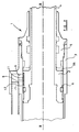
- the actuator 1 shown in Figures 1 and 2 has a piston 2 axially movable within a cylinder 3 of the actuator.
- the piston is connected to a piston rod 4, which extends through a gland 5 to the exterior of the actuator, a chamber 3A being defined between opposing faces of the piston and gland.
- a port 6 in the cylinder's peripheral wall leads via a connector 7 to a desired location.
- the piston 2 in this embodiment carries a flow restrictor device in the form of a snubbing ring 8 disposed in a circumferentially extending recess 9 in the piston. Details of the ring 8 are omitted from the lower half of Figures 1 and 2 for convenience.
- Figures 3 to 6 show the ring 8 in greater detail.
- the ring 8 has four mutually parallel grooves 9a in its outer peripheral surface, which extend along the direction of a longitudinal axis A-A of the ring 8 and are circumferentially spaced about the ring 8. It should be understood that, instead of the four grooves 9a, a different number of grooves may be provided, for example two grooves or six grooves 9a.
- the ring 8 is fitted in the actuator 1 so that the axis A-A lies along a longitudinal axis B-B of the actuator 1.
- the ring has an end portion 10 of reduced outer diameter at its right hand end in the orientation shown in Figures 4 and 5, formed by a circumferentially extending groove in the form of a step 10a in the peripheral surface of the ring 8.
- the grooves 9a in conjunction with the cylinder form axially extending passageways 11, and the step 10a in conjunction with the cylinder and a wall of the recess 9 forms a circumferential passageway 12 that places the passageways 11 in communication with one another.
- the port is restricted by the ring 8.
- the chamber 3A is closed and contains a volume of fluid, which is progressively released.
- the circumferentially outer periphery of the leading end of the piston does not seal against the cylinder and does not present a significant restriction to flow between the closed chamber 3A and the port 6.
- the rate at which the fluid is released from the chamber 3A to the port 6 determines the deceleration of the piston and is dictated by the ring 8, the outer periphery of which does seal against the cylinder.
- the desired cushioning of the piston movement can therefore be provided by selecting the sizes of the passageways 11,12 so as to permit a desired restricted flow of fluid from the chamber 3A through the passageways 11,12 to the port 6.
- a selection of rings 8 arranged to provide different restricted flow rates can be provided for use with a common design of piston body.
- a blockage may occur in the upper passageway 11 as seen in Figure 1 so as to prevent fluid flowing to the port 6 along the shortest route direct from the chamber 3A, through the nearest end portion of the passageway.
- the other passageways 11, in combination with the circumferential passageway 12 provide auxiliary restricted flow paths along which fluid can alternatively flow from the chamber 3A to the port 6.
- such auxiliary route includes an end portion of the upper passageway 11 spaced from the chamber 3A axially along the cylinder. It will, however, be understood that the auxiliary flow path may communicate with the port 6 other than via said passageway.
- the ring 8 is provided with a scarf cut 14 (Figs 3 and 4) for fitting the ring 8 to the body of the piston 2. Whilst seepage of fluid may occur through the scarf cut 14, this is not intended significantly to affect the cushioning effect of the ring.
- the grooves 9a may be formed directly in the piston 2 or in the internal wall of the cylinder 3 and a separate ring 8 dispensed with.
- the passageways may be provided by through holes in the ring, piston or cylinder.
- FIG. 7 An alternative snubbing ring 28 is shown in Figure 7, which is identical with the snubbing ring 8 except that the ring is provided with a chamfer 29 so that the outer peripheral surface of the ring 28 tapers inwardly towards the ring's leading edge 30.
- the chamfer facilitates a more progressive decelerating effect as the piston nears the end of its stroke.
- Piston rings with variously configured tapers may be provided to provide a variety of decelerating effects. For example, the angle and/or axial extent of the chamfer 29 can be varied.
Landscapes
- Engineering & Computer Science (AREA)
- Physics & Mathematics (AREA)
- Fluid Mechanics (AREA)
- Mechanical Engineering (AREA)
- General Engineering & Computer Science (AREA)
- Actuator (AREA)
Applications Claiming Priority (2)
| Application Number | Priority Date | Filing Date | Title |
|---|---|---|---|
| GBGB9910257.6A GB9910257D0 (en) | 1999-05-05 | 1999-05-05 | Piston and cylinder assembly and flow restrictor device therefor |
| GB9910257 | 1999-05-05 |
Publications (2)
| Publication Number | Publication Date |
|---|---|
| EP1050686A2 true EP1050686A2 (de) | 2000-11-08 |
| EP1050686A3 EP1050686A3 (de) | 2002-01-02 |
Family
ID=10852751
Family Applications (1)
| Application Number | Title | Priority Date | Filing Date |
|---|---|---|---|
| EP00303658A Withdrawn EP1050686A3 (de) | 1999-05-05 | 2000-05-02 | Kolben- und Zylinderaggregat und Durchflussbegrenzer dafür |
Country Status (3)
| Country | Link |
|---|---|
| US (1) | US6397725B1 (de) |
| EP (1) | EP1050686A3 (de) |
| GB (1) | GB9910257D0 (de) |
Cited By (1)
| Publication number | Priority date | Publication date | Assignee | Title |
|---|---|---|---|---|
| WO2022104182A1 (en) * | 2020-11-16 | 2022-05-19 | Caterpillar Inc. | Integrated cylinder piston and bearing as a hydraulic cushion |
Families Citing this family (1)
| Publication number | Priority date | Publication date | Assignee | Title |
|---|---|---|---|---|
| CN111425476B (zh) * | 2020-03-29 | 2022-11-22 | 龙岩市山力工程液压有限公司 | 一种液压缸 |
Family Cites Families (9)
| Publication number | Priority date | Publication date | Assignee | Title |
|---|---|---|---|---|
| US2935047A (en) * | 1957-08-02 | 1960-05-03 | Ortman Miller Machine Co Inc | Cushioned cylinder construction |
| US3296942A (en) * | 1965-03-08 | 1967-01-10 | Int Harvester Co | Deceleration control for piston of conventional hydraulic cylinder |
| US3626812A (en) * | 1970-07-09 | 1971-12-14 | Bucyrus Erie Co | Cylinder-cushioning arrangement |
| US3704650A (en) * | 1971-03-29 | 1972-12-05 | Caterpillar Tractor Co | Hydraulic jack stroke cushioning means |
| GB1363021A (en) * | 1972-02-14 | 1974-08-14 | Mangseth E | Damping fluid-pressure operated cylinder and piston arrangements |
| US4424737A (en) * | 1980-03-26 | 1984-01-10 | Kabushiki Kaisha Komatsu Seisakusho | Stroke cushioning apparatus for hydraulic cylinders |
| US4425836A (en) * | 1981-02-20 | 1984-01-17 | Government Innovators, Inc. | Fluid pressure motor |
| KR0166223B1 (ko) * | 1995-03-29 | 1998-12-01 | 서상기 | 공압실린더 |
| DE29803739U1 (de) * | 1998-03-04 | 1998-05-28 | Bümach Engineering International B.V., Emmen | Endlagendämpfung |
-
1999
- 1999-05-05 GB GBGB9910257.6A patent/GB9910257D0/en not_active Ceased
-
2000
- 2000-05-02 EP EP00303658A patent/EP1050686A3/de not_active Withdrawn
- 2000-05-03 US US09/564,109 patent/US6397725B1/en not_active Expired - Lifetime
Non-Patent Citations (1)
| Title |
|---|
| None |
Cited By (1)
| Publication number | Priority date | Publication date | Assignee | Title |
|---|---|---|---|---|
| WO2022104182A1 (en) * | 2020-11-16 | 2022-05-19 | Caterpillar Inc. | Integrated cylinder piston and bearing as a hydraulic cushion |
Also Published As
| Publication number | Publication date |
|---|---|
| EP1050686A3 (de) | 2002-01-02 |
| GB9910257D0 (en) | 1999-06-30 |
| US6397725B1 (en) | 2002-06-04 |
Similar Documents
| Publication | Publication Date | Title |
|---|---|---|
| EP3064326B1 (de) | Übersteuerung für eine automatische freisetzungs-vakuumvorrichtung | |
| KR960007334A (ko) | 유압 시스템 | |
| GB2347176A (en) | Piston cushioning mechanism for air cylinder. | |
| EP3553324A1 (de) | Ventil und hydraulisches system damit | |
| BR212016023145Y1 (pt) | Cilindro de pressão de fluido | |
| EP2829743B1 (de) | Hydraulikzylinder | |
| US6397725B1 (en) | Piston and cylinder assembly and flow restrictor device therefor | |
| US20220025913A1 (en) | Fluid pressure cylinder | |
| JP3466121B2 (ja) | クッション機構付空気圧シリンダ | |
| EP1435461A1 (de) | Pneumatikzylinder mit Dämpfungsmitteln | |
| US7021192B2 (en) | Cylinder apparatus | |
| US7032380B2 (en) | Master cylinder | |
| JPH09165986A (ja) | 自己駆動式ラム穿孔装置 | |
| KR101910699B1 (ko) | 유체압 실린더 | |
| CN101400899B (zh) | 具有软启动功能的阀门装置 | |
| JP2006526745A (ja) | 流体圧制御装置 | |
| JPH07269519A (ja) | 油圧シリンダの緩衝構造 | |
| EP3358199B1 (de) | Fluiddruckzylinder | |
| SE447666B (sv) | Ventillos, pneumatisk hammare | |
| US20090217983A1 (en) | Hydraulic valve assembly | |
| JP3227400U (ja) | 流体圧シリンダ | |
| JP5343097B2 (ja) | 流体圧シリンダ及びシリンダボディ | |
| JP2004011855A (ja) | 速度制御機構付シリンダ | |
| JP7805484B2 (ja) | 流体圧制御装置 | |
| EP1559918A2 (de) | Pneumatisches Stellglied mit Dämpfungsmittel in einem Gehäusedeckel |
Legal Events
| Date | Code | Title | Description |
|---|---|---|---|
| PUAI | Public reference made under article 153(3) epc to a published international application that has entered the european phase |
Free format text: ORIGINAL CODE: 0009012 |
|
| AK | Designated contracting states |
Kind code of ref document: A2 Designated state(s): AT BE CH CY DE DK ES FI FR GB GR IE IT LI LU MC NL PT SE Kind code of ref document: A2 Designated state(s): DE ES FR GB IT |
|
| AX | Request for extension of the european patent |
Free format text: AL;LT;LV;MK;RO;SI |
|
| PUAL | Search report despatched |
Free format text: ORIGINAL CODE: 0009013 |
|
| AK | Designated contracting states |
Kind code of ref document: A3 Designated state(s): AT BE CH CY DE DK ES FI FR GB GR IE IT LI LU MC NL PT SE |
|
| AX | Request for extension of the european patent |
Free format text: AL;LT;LV;MK;RO;SI |
|
| RAP1 | Party data changed (applicant data changed or rights of an application transferred) |
Owner name: LUCAS INDUSTRIES LIMITED |
|
| 17P | Request for examination filed |
Effective date: 20020628 |
|
| AKX | Designation fees paid |
Free format text: DE ES FR GB IT |
|
| RAP1 | Party data changed (applicant data changed or rights of an application transferred) |
Owner name: GOODRICH ACTUATION SYSTEMS LTD |
|
| 17Q | First examination report despatched |
Effective date: 20031205 |
|
| STAA | Information on the status of an ep patent application or granted ep patent |
Free format text: STATUS: THE APPLICATION IS DEEMED TO BE WITHDRAWN |
|
| 18D | Application deemed to be withdrawn |
Effective date: 20040416 |