EP1049223B1 - Schaltschrank für eine Tablettenpresse - Google Patents
Schaltschrank für eine Tablettenpresse Download PDFInfo
- Publication number
- EP1049223B1 EP1049223B1 EP00106183A EP00106183A EP1049223B1 EP 1049223 B1 EP1049223 B1 EP 1049223B1 EP 00106183 A EP00106183 A EP 00106183A EP 00106183 A EP00106183 A EP 00106183A EP 1049223 B1 EP1049223 B1 EP 1049223B1
- Authority
- EP
- European Patent Office
- Prior art keywords
- control cabinet
- panel
- netting
- pin
- cabinet according
- Prior art date
- Legal status (The legal status is an assumption and is not a legal conclusion. Google has not performed a legal analysis and makes no representation as to the accuracy of the status listed.)
- Expired - Lifetime
Links
- 238000007789 sealing Methods 0.000 claims description 14
- 239000004020 conductor Substances 0.000 claims description 12
- 229910052751 metal Inorganic materials 0.000 claims description 4
- 239000002184 metal Substances 0.000 claims description 4
- 238000003801 milling Methods 0.000 claims description 4
- 239000012780 transparent material Substances 0.000 claims description 4
- 239000000463 material Substances 0.000 claims description 2
- 239000004744 fabric Substances 0.000 description 4
- 230000002093 peripheral effect Effects 0.000 description 3
- 239000004922 lacquer Substances 0.000 description 2
- 229920003229 poly(methyl methacrylate) Polymers 0.000 description 2
- 239000004926 polymethyl methacrylate Substances 0.000 description 2
- BQCADISMDOOEFD-UHFFFAOYSA-N Silver Chemical compound [Ag] BQCADISMDOOEFD-UHFFFAOYSA-N 0.000 description 1
- 238000004026 adhesive bonding Methods 0.000 description 1
- 239000000428 dust Substances 0.000 description 1
- 239000013013 elastic material Substances 0.000 description 1
- 230000005670 electromagnetic radiation Effects 0.000 description 1
- 238000004519 manufacturing process Methods 0.000 description 1
- 229910052709 silver Inorganic materials 0.000 description 1
- 239000004332 silver Substances 0.000 description 1
- 230000000087 stabilizing effect Effects 0.000 description 1
- 239000003351 stiffener Substances 0.000 description 1
- 238000009475 tablet pressing Methods 0.000 description 1
- 238000003466 welding Methods 0.000 description 1
Images
Classifications
-
- H—ELECTRICITY
- H02—GENERATION; CONVERSION OR DISTRIBUTION OF ELECTRIC POWER
- H02B—BOARDS, SUBSTATIONS OR SWITCHING ARRANGEMENTS FOR THE SUPPLY OR DISTRIBUTION OF ELECTRIC POWER
- H02B1/00—Frameworks, boards, panels, desks, casings; Details of substations or switching arrangements
- H02B1/26—Casings; Parts thereof or accessories therefor
- H02B1/40—Wall-mounted casings; Parts thereof or accessories therefor
- H02B1/44—Hinged covers or doors
Definitions
- the invention relates to a control cabinet for a tablet press according to claim 1.
- a control cabinet in which all components and components for the electrical control of the tablet press and peripherals are included.
- Such cabinets have, as usual, a corpus made of sheet metal and a door through which the interior of the body and thus the individual parts in the cabinet are accessible.
- the cabinet door is usually closed and may only be opened by authorized persons. However, this means that faults occurring in or displayed in the control cabinet are not available for immediate access if the authorized person is not nearby.
- Out DE 91 06 114 U has become known a cabinet for electrical switchgear, in which an opening through a window with transparent Slice is covered.
- the cabinet consists of wall, ceiling and floor sections made of sheet metal, and the transparent pane consists of three superimposed panels, between two panels, a mesh of electrically conductive material is arranged.
- the window is fastened to the carcass by means of a sheet metal border, and the screw fastening for this purpose simultaneously forms a contact device which connects the braid electrically to a section of the carcass.
- the invention is therefore an object of the invention to provide a cabinet for a tablet press with a door that allows insight into the interior of the cabinet even when the door is closed, which is also shielded against electromagnetic waves and at the same time can be cleaned well.
- the door panel as the window in the prior art described completely made of transparent material.
- the door panel is composed of at least three layers, namely two outer panels of sufficiently stable transparent material, such as acrylic glass, and arranged between the panels Braid made of an electrically conductive material.
- the braid is designed so that it does not obstruct the view through the door panel substantially. In this way, an operator can easily look into the interior of a cabinet and determine whether certain indicator lights or the like respond or indicate an alarm or fault situation.
- the door panel is, as already mentioned, built only from the parts described. A stabilizing border or the like is not required. This has the significant advantage that the cabinet from the outside may have smooth surfaces throughout, which is important for hygienic reasons.
- the invention provides that the inner panel at the edge releases a strip of the outer panel optionally including the braid and connected to the associated housing portion, a sealing strip of electrically conductive material, which mechanically with the exposed strip electrically contacts the braid when the door is in its closed position.
- the exposed strip is either covered by the mesh and provided with an electrically conductive layer, which in turn is electrically connected to the braid.
- a preferred solution according to the invention is that the inner panel is milled laterally by a milling process including the wire mesh, so that the adjacent panel is exposed.
- the exposed strip including the edge of the milled-off panel, is coated with a layer of conductive material, for example a conductive lacquer, in particular a silver conductive lacquer.
- the sealing strip of conductive material sealingly engages the conductive layer and simultaneously makes electrical contact therewith.
- the conductive layer is conductively connected to the braid.
- the sealing strip is formed as a box-shaped profile, so that a wide-area contact with the conductive layer is made.
- the sealing strip is located in Hinge area of the door panel, but it can also be attached to all four sides of the door opening, as stated above.
- a pin extending from the door panel of electrically conductive material may be provided which is connected to the hinge for the door and in turn to the braid.
- the pin may be a common attachment pin that connects the hinge to the door panel.
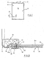
- a control cabinet 10 which has a body 12 made of metallic sheet material.
- the rectangular cabinet 10 has a front opening 14 which can be closed by a door panel 16.
- the door panel is articulated on the left side by two hinges on the body 12, wherein mounting pins 18, 20 are indicated for fixing the door panel 16 to the hinges.
- a so-called Vorreiberstatt is arranged, which can be rotated and having at the inner end a transverse approach, which engages behind an edge of the body 12 to lock the door panel 16.
- the door panel 16 consists of two superimposed panels 24a, 26 which are formed of transparent material, such as acrylic glass. Between the panels 24a, 26 is a braid 28 made of conductive material, but does not obstruct the view through the door 16.
- the pin 20 has a flange-like head 30 and a threaded shaft 32 which extends through a bore of the panels 24a, 26.
- the threaded shaft 32 also extends through a portion 34 of a box-like hinge profile 36, which has a bearing eye 38 near the opening 14, which is mounted on a bearing pin 40 which is attached by means of a plate portion 42 to the corresponding wall of the body 12.
- the hinge profile 36 is adapted to the inner contour of the body 12, which is not the case in the present case is of particular importance.
- a nut 48 secures the portion 34, which is parallel to the inside of the panel 24a, to the panel 24a so that the door panel 16 is suspended and can be pivoted from the closed position to the open position and vice versa.
- Fig. 2 only one hinge is shown, wherein the cabinet 10 after Fig. 1 has two hinges. The second is the same after Fig. 2 built up.
- a sealing strip 48a is attached at the inwardly drawn portion 46, to which also the plate portion 42 is fixed, for example by welding.
- the sealing strip 48a made of elastic material can extend over the entire opening 14 of the cabinet 10. It prevents the ingress of moisture and dust into the interior of the cabinet.
- the threaded shank 32 is surrounded by a sleeve-shaped seal 52 which rests against flat gaskets 54 and 58 of conductive material at both ends.
- Characterized the braid 28 is electrically connected to the hinge profile 36, which in turn is electrically connected to the body 12, which is constructed of electrically conductive sheets.
- the inner panel 24a has smaller dimensions, so that a strip of the panel 26 and the braid 28 is exposed. Such a strip can be extend all around the door leaf.
- the sealing stiffener 48a is made of electrically conductive material. It is in electrical contact with the braid 28 when the door panel 12 is in the closed position as shown in FIG Fig. 2 is shown. In this way, a contacting of the braid 28 with the body 12 over a large length, which may extend around the entire peripheral surface of the door panel 16 a.
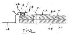
- a door panel 16b to recognize which consists of an inner panel 24b, a middle panel 25 and an outer panel 26b.
- a wire mesh 28 is disposed between the panels 24b and 25.
- the hinge is suitably connected to the body 12, which is only indicated in FIG. 4. This is in the door opening, as indicated at 27, provided with an inwardly curved edge 60 to which a box-shaped in cross-section sealing strip 62 made of conductive material, for example by gluing.
- a recess 64 is formed which is conductive Layer, for example, coated with a conductive ink 66.
- the left edge of the panel 24b is coated so that the layer 66 is electrically connected to the fabric 28.
- the recess 64 is formed together with the sealing strip 62 so that the sealing strip when closed Door panel 16b engages the recess 64 and abuts against the conductive layer 66 on the panel 25 and at the same time to the lateral edge of the panel 24b with the associated conductive fabric 28. In this way, an effective electrical connection between the fabric 28 and the conductive Body 12 made. The effort for this is relatively low.
- the panels 24b, 25 and 26b are operatively connected together without the need for a border or frame. Only the milling away of a strip-shaped portion of the panel 24b and the braid 28 requires an additional manufacturing process.
Landscapes
- Engineering & Computer Science (AREA)
- Power Engineering (AREA)
- Casings For Electric Apparatus (AREA)
- Shielding Devices Or Components To Electric Or Magnetic Fields (AREA)
Description
- Die Erfindung bezieht sich auf einen Schaltschrank für eine Tablettenpresse nach dem Patentanspruch 1.
- Zum System einer Tablettenpressvorrichtung gehört neben der eigentlichen Tablettenpresse und sonstigen Peripheriegeräten ein Schaltschrank, in dem alle Komponenten und Bauteile für die elektrische Ansteuerung der Tablettenpresse und der Peripheriegeräte enthalten sind. Derartige Schaltschränke haben wie üblich einen Korpus aus Metallblech und eine Tür, über die das Innere des Korpus und damit die einzelnen Teile im Schaltschrank zugänglich sind. Aus Sicherheitsgründen ist die Schaltschranktür üblicherweise geschlossen und darf nur von autorisierten Personen geöffnet werden. Das bedeutet jedoch, daß Störungen, die im Schaltschrank auftreten oder in diesem angezeigt sind, nicht dem sofortigen Zugriff zur Verfügung stehen, wenn die autorisierte Person nicht in der Nähe ist.
- Aus
DE 91 06 114 U ist ein Schaltschrank für elektrische Schaltanlagen bekannt geworden, bei dem eine Öffnung durch ein Fenster mit durchsichtiger Scheibe abgedeckt ist. Der Schaltschrank besteht aus Wand-, Decken- und Bodenabschnitten aus Metallblech, und die durchsichtige Scheibe besteht aus drei übereinander angeordneten Paneelen, wobei zwischen zwei Paneelen ein Geflecht aus elektrisch leitendem Material angeordnet ist. Das Fenster ist mittels einer Blechumrandung am Korpus befestigt, und die Schraubbefestigung hierfür bildet gleichzeitig eine Kontaktvorrichtung, die das Geflecht elektrisch mit einem Abschnitt des Korpus verbindet. - Daher liegt der Erfindung die Aufgabe zugrunde, einen Schaltschrank für eine Tablettenpresse mit einer Tür zu schaffen, die Einblick in das Innere des Schaltschranks auch bei geschlossener Tür erlaubt, die ferner gegen elektromagnetische Wellen abgeschirmt ist und sich zugleich gut reinigen läßt.
- Diese Aufgabe wird durch die Merkmale des Patentanspruchs 1 gelöst.
- Bei dem erfindungsgemäßen Schaltschrank besteht die Türplatte wie das Fenster im beschriebenen Stand der Technik komplett aus durchsichtigem Material. Die Türplatte setzt sich aus mindestens drei Schichten zusammen, nämlich aus zwei äußeren Paneelen aus ausreichend stabilem durchsichtigem Material, beispielsweise Acrylglas, und einem zwischen den Paneelen angeordneten Geflecht aus einem elektrisch leitenden Material. Das Geflecht ist so ausgeführt, daß es den Durchblick durch die Türplatte im wesentlichen nicht behindert. Auf diese Weise kann ein Bediener problemlos in das Innere eines Schaltschranks hinein schauen und feststellen, ob bestimmte Anzeigeleuchten oder dergleichen ansprechen bzw. eine Alarm- oder Fehlersituation anzeigen.
- Die Türplatte ist, wie schon erwähnt, nur aus den beschriebenen Teilen aufgebaut. Eine stabilisierende Umrandung oder dergleichen ist nicht erforderlich. Dies hat den wesentlichen Vorteil, daß der Schaltschrank von außen durchgehend glatte Flächen aufweisen kann, was aus hygienischen Gründen von Wichtigkeit ist.
- Für die elektrische Verbindung des Geflechts mit dem Korpus sieht die Erfindung vor, daß das innere Paneel am Rand einen Streifen des äußeren Paneels gegebenenfalls einschließlich des Geflechts freigibt und mit dem zugehörigen Gehäuseabschnitt ein Dichtstreifen aus elektrisch leitenden Material verbunden ist, der mit dem freigelegten Streifen mechanisch mit dem Geflecht elektrisch in Kontakt tritt, wenn die Tür in ihrer Schließstellung ist. Der freigelegte Streifen ist entweder vom Geflecht überdeckt und mit einer elektrisch leitenden Schicht versehen, die ihrerseits mit dem Geflecht elektrisch verbunden ist.
- Es ist vorstellbar, den Dichtstreifen um die gesamte Türöffnung von innen herum anzuordnen und jeweils mit einem freigelegten Abschnitt des Geflechts in Eingriff zu bringen. Dadurch wird zwar eine Kontaktierung nur im geschlossenen Zustand der Tür hergestellt, ein Schutz gegen elektromagnetische Strahlung findet jedoch auch bei geöffneten Türen herkömmlicher Schaltschränke nicht statt.
- Eine bevorzugte Lösung nach der Erfindung besteht darin, daß durch einen Fräsvorgang das innenliegende Paneel seitlich abgefräst wird einschließlich des Drahtgeflechts, so daß das benachbarte Paneel freigelegt ist. Der freigelegte Streifen einschließlich der Kante des abgefrästen Paneels wird mit einer Schicht aus leitendem Material beschichtet, beispielsweise einem Leitlack, insbesondere einem Silberleitlack. Der Dichtstreifen aus leitendem Material tritt dichtend mit der Leitschicht in Eingriff und stellt gleichzeitig mit dieser einen elektrischen Kontakt her. Die Leitschicht ist mit dem Geflecht leitend verbunden. Vorzugsweise ist der Dichtstreifen als kastenförmiges Profil ausgebildet, so daß ein breitflächiger Kontakt mit der Leitschicht hergestellt ist. Vorzugsweise befindet sich der Dichtstreifen im Scharnierbereich der Türplatte, er kann jedoch auch an allen vier Seiten der Türöffnung angebracht werden, wie weit oben ausgeführt.
- Zusätzlich kann ein durch die Türplatte sich erstreckender Stift aus elektrisch leitendem Material vorgesehen sein, der mit dem Scharnier für die Tür und seinerseits mit dem Geflecht verbunden ist. Der Stift kann ein üblicher Befestigungsstift sein, der das Scharnier mit der Türplatte verbindet.
- Ausführungsbeispiele werden anhand von Zeichnungen nachfolgend näher erläutert.
- Fig. 1
- zeigt die Vorderansicht eines Schaltschrank nach der Erfindung.
- Fig. 2
- zeigt einen Schnitt durch den Türbereich des Schaltschranks nach
Fig. 1 entlang der Linie 2-2. - Fig. 3
- zeigt eine gegenüber
Fig. 2 abgewandelte Art der Kontaktierung. - In
Fig. 1 ist ein Schaltschrank 10 angedeutet, der einen Korpus 12 aufweist aus metallischem Blechmaterial. Der quaderförmige Schrank 10 weist eine vordere Öffnung 14 auf, welche durch eine Türplatte 16 verschließbar ist. - Die Türplatte ist an der linken Seite durch zwei Scharniere am Korpus 12 angelenkt, wobei Befestigungsstifte 18, 20 zur Befestigung der Türplatte 16 an den Scharnieren angedeutet sind. Bei 22 ist ein sog. Vorreiberstift angeordnet, der verdreht werden kann und der am inneren Ende einen Queransatz aufweist, der hinter eine Kante des Korpus 12 greift, um die Türplatte 16 zu verriegeln.
- In
Fig. 2 ist zu erkennen, daß die Türplatte 16 aus zwei übereinanderliegenden Paneelen 24a, 26 besteht, die aus durchsichtigem Material geformt sind, beispielsweise Acrylglas. Zwischen den Paneelen 24a, 26 befindet sich ein Geflecht 28 aus leitendem Material, das jedoch die Durchsicht durch die Tür 16 nicht behindert. - In
Fig. 2 ist zu erkennen, daß der Stift 20 einen flanschartigen Kopf 30 und einen Gewindeschaft 32 aufweist, der sich durch eine Bohrung der Paneele 24a, 26 hindurcherstreckt. Der Gewindeschaft 32 erstreckt sich auch durch einen Abschnitt 34 eines kastenartigen Scharnierprofils 36, das nahe der Öffnung 14 ein Lagerauge 38 aufweist, das auf einen Lagerstift 40 aufgesteckt ist, der mit Hilfe eines Plattenabschnitts 42 an der entsprechenden Wand des Korpus 12 angebracht ist. Das Scharnierprofil 36 ist an die Innenkontur des Korpus 12 angepaßt, was jedoch für den vorliegenden Fall nicht von besonderer Bedeutung ist. Eine Mutter 48 befestigt den Abschnitt 34, der parallel zur Innenseite des Paneels 24a verläuft, mit dem Paneel 24a, so daß die Türplatte 16 aufgehängt ist und aus der Schließstellung in die Öffnungsstellung und umgekehrt verschwenkt werden kann. InFig. 2 ist lediglich ein Scharnier dargestellt, wobei der Schaltschrank 10 nachFig. 1 zwei Scharniere aufweist. Das zweite ist gleich dem nachFig. 2 aufgebaut. - An dem nach innen gezogenen Abschnitt 46, an dem auch der Plattenabschnitt 42 beispielsweise durch Schweißung befestigt ist, ist ein Dichtstreifen 48a angebracht. Der Dichtstreifen 48a aus elastischem Material kann über die gesamte Öffnung 14 des Schranks 10 verlaufen. Er verhindert das Eindringen von Feuchtigkeit und Staub in das Innere des Schrankes.
- Der Gewindeschaft 32 wird von einer hülsenförmigen Dichtung 52 umgeben, die an beiden Enden gegen Flachdichtungen 54 bzw. 58 aus leitendem Material anliegt. Dadurch ist das Geflecht 28 elektrisch wirksam mit dem Scharnierprofil 36 verbunden, das seinerseits elektrisch mit dem Korpus 12 verbunden ist, der aus elektrisch leitenden Blechen aufgebaut ist.
- Das innere Paneel 24a hat geringere Abmessungen, so daß ein Streifen des Paneels 26 und des Geflechts 28 frei liegt. Ein solcher Streifen kann sich rundherum um das Türblatt erstrecken. Der Dichtsteifen 48a besteht aus elektrisch leitendem Material. Er steht in elektrischem Kontakt mit dem Geflecht 28, wenn die Türplatte 12 in der Schließstellung ist, wie sie in
Fig. 2 gezeigt ist. Auf diese Weise erfolgt eine Kontaktierung des Geflechts 28 mit dem Korpus 12 über eine große Länge, die sich um die gesamte Umfangsfläche der Türplatte 16a erstrecken kann. - Bei der Ausführungsform nach
Fig. 3 ist eine Türplatte 16b zu erkennen, die aus einem inneren Paneel 24b, einem mittleren Paneel 25 und einem äußeren Paneel 26b besteht. Ein Drahtgeflecht 28 ist zwischen den Paneelen 24b und 25 angeordnet. Durch alle Paneele hindurch erstreckt sich eine Bohrung 52, die mit einem Bolzen durchsetzt sein kann, der Teil eines Scharniers ist, wie es inFig. 2 gezeigt und weiter oben beschrieben ist. Hierauf sollt nicht mehr weiter eingegangen werden. Das Scharnier ist in geeigneter Weise mit dem Korpus 12 verbunden, der in Fig. 4 nur angedeutet ist. Dieser ist im Bereich der Türöffnung, wie bei 27 angedeutet, mit einem nach innen gebogenen Rand 60 versehen, an dem ein im Querschnitt kastenförmiger Dichtstreifen 62 aus leitendem Material angebracht ist, beispielsweise durch Klebung. - Wie aus
Fig. 3 ferner zu erkennen, ist durch Fräsen des Paneels 24b und des leitenden Gewebes 28 eine Ausnehmung 64 geformt, die mit einer leitfähigen Schicht, beispielsweise mit einem Leitlack 66 beschichtet ist. Dabei wird auch die linke Kante des Paneels 24b beschichtet, so daß die Schicht 66 mit dem Gewebe 28 elektrisch leitend verbunden ist. Die Ausnehmung 64 ist zusammen mit dem Dichtstreifen 62 so geformt, daß der Dichtstreifen bei geschlossener Türplatte 16b in die Ausnehmung 64 eingreift und sich gegen die Leitschicht 66 auf dem Paneel 25 anlegt und zugleich auch an die seitliche Kante des Paneels 24b mit dem zugehörigen leitfähigen Gewebe 28. Auf diese Weise ist eine wirksame elektrische Verbindung zwischen dem Gewebe 28 und dem leitfähigem Korpus 12 hergestellt. Der Aufwand hierfür ist relativ gering. Die Paneele 24b, 25 und 26b sind wirksam miteinander verbunden, ohne daß eine Umrandung oder ein Rahmen erforderlich ist. Lediglich das Wegfräsen eines streifenförmigen Abschnitts von Paneel 24b und des Geflechts 28 erfordert einen zusätzlichen Fertigungsgang.
Claims (7)
- Schaltschrank für eine Tablettenpresse, mit- einem Korpus (12) mit Wand-, Decken- und Bodenabschnitten aus Metallblech- einer Platte an seiner Vorderseite, welche eine Korpusöffnung (14) verschließt und aus mindestens zwei Paneelen (26, 24a; 26b, 24b, 25) aus durchsichtigem Material besteht, zwischen denen ein Geflecht (28) aus elektrisch leitendem Material angeordnet ist,gekennzeichnet durch eine über ein Scharnier (36) am Korpus (12) angeschlagene Türplatte (16, 16b), die nur aus den mindestens zwei Paneelen (26, 24a; 26b, 24b, 25) ohne Umrandung besteht, wobei das innere Paneel (24a, 24b) am Rand einen Streifen des äußeren Paneels (25, 26) mit Geflecht oder einer Leitschicht (66) freiläßt und mit dem zugekehrten Gehäuseabschnitt ein Dichtstreifen (48a; 62) aus elektrisch leitendem Material verbunden ist, der mit dem freigelegten Streifen in mechanischem und mit dem Geflecht unmittelbar oder über die Leitschicht (66) in elektrischen Kontakt tritt, wenn die Tür (16, 16b) in ihrer Schließstellung ist.
- Schaltschrank nach Anspruch 1, dadurch gekennzeichnet, daß der Dichtstreifen (62) Kastenprofil aufweist.
- Schaltschrank nach Anspruch 1 oder 2, dadurch gekennzeichnet, daß das innere Paneel (24b) durch Wegfräsung von Material und gegebenenfalls des Geflechts (28) den Streifen freiläßt.
- Schaltschrank nach Anspruch 3, dadurch gekennzeichnet, daß mindestens ein sich durch die Türplatte (16, 16b) erstreckender und mit einem Scharnier (36) verbundener Stift (20) mit dem Geflecht (28) elektrisch leitend verbunden ist.
- Schaltschrank nach Anspruch 4, dadurch gekennzeichnet, daß der Stift (20) Befestigungsmittel ist.
- Schaltschrank nach Anspruch 4 oder 5, dadurch gekennzeichnet, daß in einer erweiterten Bohrung des einen Paneels (26) eine elektrisch leitende Kontaktbuchse (52) den Stift (20) umgibt und an einem Stirnende gegen das Geflecht (28) anliegt und am anderen Ende gegen einen Kopf (30) des Stiftes (20), wobei die Länge der Kontaktbuchse (50) etwas größer ist als die Dicke des Paneels (16a).
- Schaltschrank nach Anspruch 6, dadurch gekennzeichnet, daß zwischen dem Kopf (30) des Stiftes (20) und der Kontaktbuchse (50) eine elektrisch leitende Dichtung (58) angeordnet ist.
Applications Claiming Priority (2)
| Application Number | Priority Date | Filing Date | Title |
|---|---|---|---|
| DE19918804A DE19918804C2 (de) | 1999-04-26 | 1999-04-26 | Schaltschrank für eine Tablettenpresse |
| DE19918804 | 1999-04-26 |
Publications (3)
| Publication Number | Publication Date |
|---|---|
| EP1049223A2 EP1049223A2 (de) | 2000-11-02 |
| EP1049223A3 EP1049223A3 (de) | 2002-08-28 |
| EP1049223B1 true EP1049223B1 (de) | 2009-10-28 |
Family
ID=7905836
Family Applications (1)
| Application Number | Title | Priority Date | Filing Date |
|---|---|---|---|
| EP00106183A Expired - Lifetime EP1049223B1 (de) | 1999-04-26 | 2000-03-21 | Schaltschrank für eine Tablettenpresse |
Country Status (3)
| Country | Link |
|---|---|
| US (1) | US6426458B1 (de) |
| EP (1) | EP1049223B1 (de) |
| DE (2) | DE19918804C2 (de) |
Families Citing this family (3)
| Publication number | Priority date | Publication date | Assignee | Title |
|---|---|---|---|---|
| JP4602053B2 (ja) * | 2004-11-16 | 2010-12-22 | ナブテスコ株式会社 | 磁気シールドドア及び磁気シールド室 |
| US7906735B2 (en) * | 2007-07-05 | 2011-03-15 | Raytheon Company | Electrically conductive dynamic environmental seal |
| US8993898B2 (en) * | 2012-06-26 | 2015-03-31 | ETS-Lindgren Inc. | Movable EMF shield, method for facilitating rapid imaging and treatment of patient |
Family Cites Families (6)
| Publication number | Priority date | Publication date | Assignee | Title |
|---|---|---|---|---|
| US4381421A (en) * | 1980-07-01 | 1983-04-26 | Tektronix, Inc. | Electromagnetic shield for electronic equipment |
| DE9106114U1 (de) * | 1991-05-17 | 1991-07-04 | Walter Becker GmbH, 66299 Friedrichsthal | Fenster eines Gehäuses, insbesondere für elektrische Schaltanlagen, Rechner o.dgl. |
| DE4127467A1 (de) * | 1991-08-20 | 1993-02-25 | Schroff Gmbh | Geraeteschrank |
| US5136119A (en) * | 1991-09-18 | 1992-08-04 | The United States Of America As Represented By The Secretaty Of The Navy | Lightweight portable EMI shielding container |
| US5981927A (en) * | 1996-12-13 | 1999-11-09 | Osepchuk; John | High visibility microwave oven door with screen and microwave absorbing material |
| DE29621869U1 (de) * | 1996-12-17 | 1997-04-03 | Striebel & John Gmbh & Co Kg, 77880 Sasbach | Einrichtung zur vorderseitigen Abdeckung für Installationskästen, insbesondere für Unterputz-Installationskästen |
-
1999
- 1999-04-26 DE DE19918804A patent/DE19918804C2/de not_active Expired - Fee Related
-
2000
- 2000-03-21 EP EP00106183A patent/EP1049223B1/de not_active Expired - Lifetime
- 2000-03-21 DE DE50015776T patent/DE50015776D1/de not_active Expired - Lifetime
- 2000-04-26 US US09/558,365 patent/US6426458B1/en not_active Expired - Lifetime
Also Published As
| Publication number | Publication date |
|---|---|
| EP1049223A3 (de) | 2002-08-28 |
| DE19918804C2 (de) | 2003-02-27 |
| DE19918804A1 (de) | 2000-11-16 |
| EP1049223A2 (de) | 2000-11-02 |
| DE50015776D1 (de) | 2009-12-10 |
| US6426458B1 (en) | 2002-07-30 |
Similar Documents
| Publication | Publication Date | Title |
|---|---|---|
| DE10051171B4 (de) | Wippschalter | |
| DE112013007355T5 (de) | Scharnier für eine Klapptüre | |
| DE4203117C2 (de) | Scharniervorrichtung | |
| EP0528239B1 (de) | Geräteschrank | |
| DE19707594A1 (de) | Anschraubscharnier für geerdete Schaltschranktüren, Apparateverkleidungen o. dgl. | |
| DE69633174T2 (de) | Mikrowellenofen mit verbesserter Tür | |
| EP0634550B1 (de) | Vorreiberverschluss | |
| DE69316904T2 (de) | Vorrichtung zur gelenkigen Verbindung und Kuppeln einer Tür eines zum Einbau in einen Möbelelement bestimmten elektrischen Einbaugerätes an einem Türpaneel des Möbelementes, sa dass der Raum des Möbelelementes optimal benutzt wird | |
| DE10345919B4 (de) | Insektenschutztür oder -fenster | |
| EP0862252B1 (de) | Schrank zur Aufnahme von elektrischen und elektronischen Komponenten | |
| DE60026055T2 (de) | Tür | |
| EP2318791B1 (de) | Abdeckleisten-baugruppe eines haushaltsgerätes | |
| DE19918804C2 (de) | Schaltschrank für eine Tablettenpresse | |
| EP1568833A2 (de) | Schliessblech für ein Fenster oder eine Tür | |
| AT392724B (de) | Schrank mit eingebautem kuehlschrank od.dgl. | |
| DE4309044A1 (de) | Elektronikgehäuse mit Tür und Laufwerk o. dgl. | |
| DE102012108991B4 (de) | Schaltkontakt | |
| DE3512856C2 (de) | Gepanzerte Tür | |
| DE19913766A1 (de) | Einrichtung zur Sicherung eines Objektes gegen unbefugten Zugriff | |
| DE3015945C2 (de) | Installationsverteiler | |
| EP2820729B1 (de) | Schaltschranktür | |
| DE102005012856A1 (de) | Schliessleistenaggregat für ein Türschloss | |
| DE69308455T2 (de) | Ein verdeckt angeordnetes Scharnier für ein Paneel einer Schalttafel | |
| DE102005013343B3 (de) | Den Durchgang elektrischer Felder verhindernde Tür | |
| DE19913657C1 (de) | Tür, insbesondere zum Verschließen von Gehäusen zur Aufnahme von elektronischen Baugruppen |
Legal Events
| Date | Code | Title | Description |
|---|---|---|---|
| PUAI | Public reference made under article 153(3) epc to a published international application that has entered the european phase |
Free format text: ORIGINAL CODE: 0009012 |
|
| 17P | Request for examination filed |
Effective date: 20000328 |
|
| AK | Designated contracting states |
Kind code of ref document: A2 Designated state(s): AT BE CH CY DE DK ES FI FR GB GR IE IT LI LU MC NL PT SE |
|
| AX | Request for extension of the european patent |
Free format text: AL;LT;LV;MK;RO;SI |
|
| PUAL | Search report despatched |
Free format text: ORIGINAL CODE: 0009013 |
|
| RAP1 | Party data changed (applicant data changed or rights of an application transferred) |
Owner name: FETTE GMBH |
|
| AK | Designated contracting states |
Kind code of ref document: A3 Designated state(s): AT BE CH CY DE DK ES FI FR GB GR IE IT LI LU MC NL PT SE |
|
| AX | Request for extension of the european patent |
Free format text: AL;LT;LV;MK;RO;SI |
|
| AKX | Designation fees paid |
Designated state(s): CH DE FR GB IT LI |
|
| 17Q | First examination report despatched |
Effective date: 20070507 |
|
| GRAP | Despatch of communication of intention to grant a patent |
Free format text: ORIGINAL CODE: EPIDOSNIGR1 |
|
| GRAS | Grant fee paid |
Free format text: ORIGINAL CODE: EPIDOSNIGR3 |
|
| GRAA | (expected) grant |
Free format text: ORIGINAL CODE: 0009210 |
|
| AK | Designated contracting states |
Kind code of ref document: B1 Designated state(s): CH DE FR GB IT LI |
|
| REG | Reference to a national code |
Ref country code: GB Ref legal event code: FG4D Free format text: NOT ENGLISH |
|
| REG | Reference to a national code |
Ref country code: CH Ref legal event code: EP Ref country code: CH Ref legal event code: NV Representative=s name: ISLER & PEDRAZZINI AG |
|
| REF | Corresponds to: |
Ref document number: 50015776 Country of ref document: DE Date of ref document: 20091210 Kind code of ref document: P |
|
| PLBE | No opposition filed within time limit |
Free format text: ORIGINAL CODE: 0009261 |
|
| STAA | Information on the status of an ep patent application or granted ep patent |
Free format text: STATUS: NO OPPOSITION FILED WITHIN TIME LIMIT |
|
| 26N | No opposition filed |
Effective date: 20100729 |
|
| REG | Reference to a national code |
Ref country code: DE Ref legal event code: R082 Ref document number: 50015776 Country of ref document: DE Representative=s name: HAUCK PATENT- UND RECHTSANWAELTE, DE Effective date: 20110621 Ref country code: DE Ref legal event code: R081 Ref document number: 50015776 Country of ref document: DE Owner name: FETTE COMPACTING GMBH, DE Free format text: FORMER OWNER: FETTE GMBH, 21493 SCHWARZENBEK, DE Effective date: 20110621 Ref country code: DE Ref legal event code: R082 Ref document number: 50015776 Country of ref document: DE Representative=s name: HAUCK PATENTANWALTSPARTNERSCHAFT MBB, DE Effective date: 20110621 |
|
| PGFP | Annual fee paid to national office [announced via postgrant information from national office to epo] |
Ref country code: CH Payment date: 20140324 Year of fee payment: 15 |
|
| PGFP | Annual fee paid to national office [announced via postgrant information from national office to epo] |
Ref country code: IT Payment date: 20140327 Year of fee payment: 15 Ref country code: FR Payment date: 20140319 Year of fee payment: 15 |
|
| PGFP | Annual fee paid to national office [announced via postgrant information from national office to epo] |
Ref country code: GB Payment date: 20140324 Year of fee payment: 15 |
|
| PGFP | Annual fee paid to national office [announced via postgrant information from national office to epo] |
Ref country code: DE Payment date: 20140508 Year of fee payment: 15 |
|
| REG | Reference to a national code |
Ref country code: DE Ref legal event code: R119 Ref document number: 50015776 Country of ref document: DE |
|
| REG | Reference to a national code |
Ref country code: CH Ref legal event code: PL |
|
| GBPC | Gb: european patent ceased through non-payment of renewal fee |
Effective date: 20150321 |
|
| PG25 | Lapsed in a contracting state [announced via postgrant information from national office to epo] |
Ref country code: IT Free format text: LAPSE BECAUSE OF NON-PAYMENT OF DUE FEES Effective date: 20150321 |
|
| REG | Reference to a national code |
Ref country code: FR Ref legal event code: ST Effective date: 20151130 |
|
| PG25 | Lapsed in a contracting state [announced via postgrant information from national office to epo] |
Ref country code: CH Free format text: LAPSE BECAUSE OF NON-PAYMENT OF DUE FEES Effective date: 20150331 Ref country code: DE Free format text: LAPSE BECAUSE OF NON-PAYMENT OF DUE FEES Effective date: 20151001 Ref country code: GB Free format text: LAPSE BECAUSE OF NON-PAYMENT OF DUE FEES Effective date: 20150321 Ref country code: LI Free format text: LAPSE BECAUSE OF NON-PAYMENT OF DUE FEES Effective date: 20150331 |
|
| PG25 | Lapsed in a contracting state [announced via postgrant information from national office to epo] |
Ref country code: FR Free format text: LAPSE BECAUSE OF NON-PAYMENT OF DUE FEES Effective date: 20150331 |